
Abstract
Precision measurement is the premise of precision motion control. When a worktable is operating, the synchronization of multiaxial sampling will directly affect the precision of table position conversion. In this paper, a precise synchrone mechanism for multiaxial laser measurement was proposed. Tests showed that the maximum synchronous sampling time error from 6 laser axes was 0.404 ns. When the table was moving at 1 m/s, the induced maximum displacement conversion error was 0.202 nm, which satisfied the strict nanometer-scale requirement imposed by ultra-precise motion control for position measurement.
1. Introduction
Lithography machine (Figure 1(a)) is the core and most complex device in an IC equipment. For a 65 nm lithography machine at an acceleration of 1.6 g and a moving speed of 2 m/s, the synchronization error between a work-piece table and a mask table should be MA < 3.2 nm and MSD < 6.5 nm [1–6]. This movement requirement which is nearly the physical limit becomes the key for development of high-precision lithography machine. The premise for precision motion control is to build a set of precise displacement measuring systems. In the field of precise position measurement, laser heterodyne interference measurement (Figure 1(b)) is widely applied owing to its rapid response, wide measuring scale, high signal-to-noise, ability to overcome directional fuzziness, and without interference from light intensity variation [7–10].
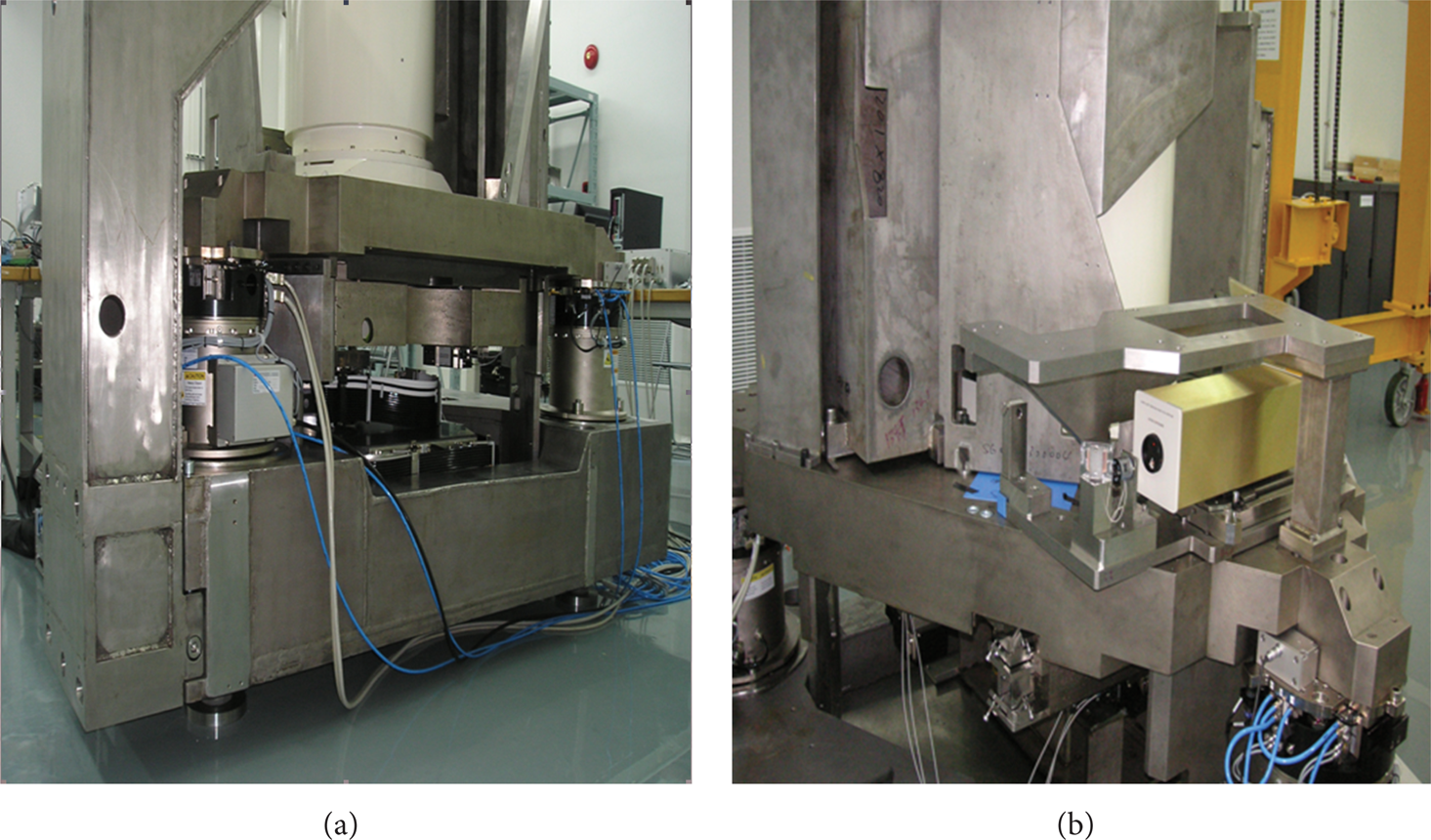
(a) IC lithography machine; (b) laser interference measuring system.
A working lithography machine should synchronously measure about 10 axes on a worktable and a mask table and deliver the data through a high speed bus to a data acquisition board. The overall structure of the position measuring system is shown in Figure 2. In a nanometer-scale multiaxial precise laser measuring system, when the table is moving at high speed, the interaxial synchronization of measurement/sampling will directly affect the precision of table position conversion. Excessively large measurement error will result in the failure of precision motion control. By compensating the data delay in the light path and electric system through a measurement and processing electric system, the interaxial data delay difference can be controlled within 1 ns, but this system is too complex and unfeasible [7].

The overall structure of the position measuring system.
Therefore, in this paper, a precise synchrone mechanism for multiaxial laser measurement was proposed. This mechanism ensures that the sampling time between all laser axes can be controlled to nanosecond scale and satisfy the strict requirement imposed by ultra-precise motion control for position measurement.
2. The Measuring Structure and the Measuring Model in the Worktable
In this section, the structure of the multiaxial synchronized measuring system and the method for positioning calculation in the worktable were illustrated with exposure as example. However, we only discussed the horizontal control of position measurement. Figure 3 shows the laser measuring structure of the work-piece table (a) and the distributions of measuring beams in the X-phase (b) and Y-phase (c).
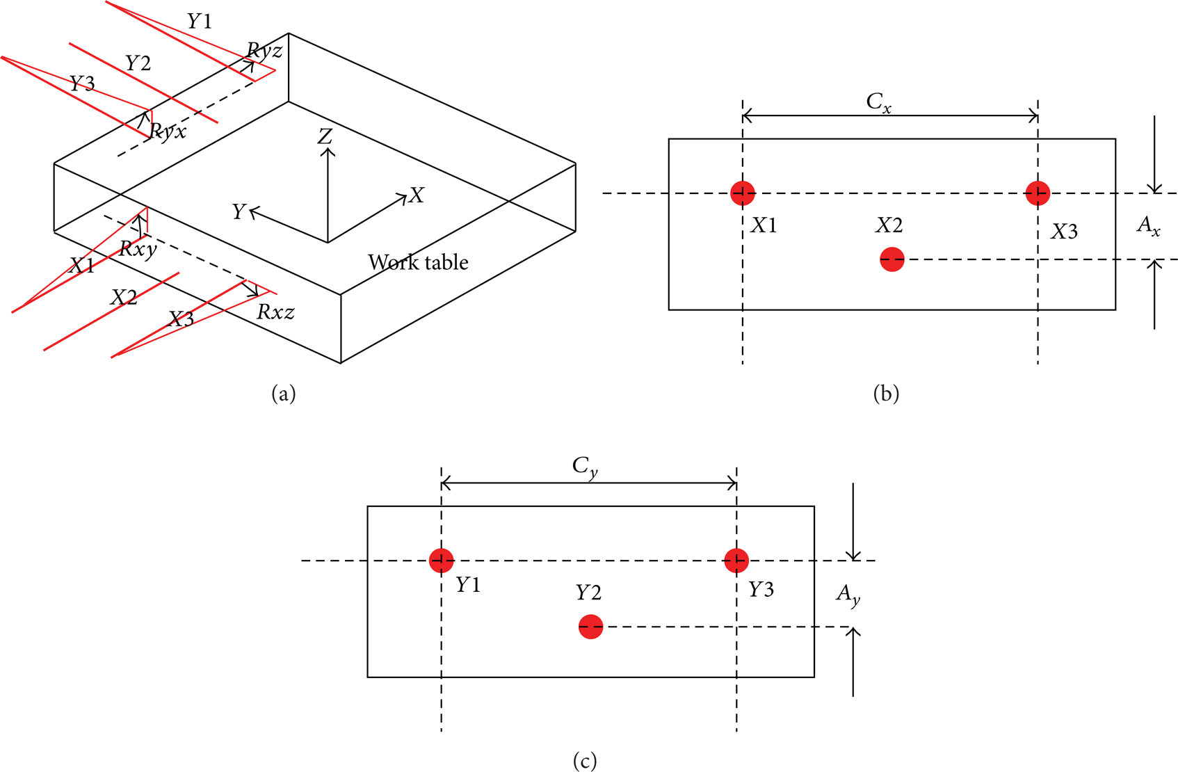
The laser measuring structure of the work table (a) and the distributions of beams in the X-phase (b) and Y-phase (c).
The measuring system measures the worktable's real-time position in the coordinate system, including its displacements in parallel to X-axis and to Y-axis, as well as the rotations around X-axis, around Y-axis, and around Z-axis. Moreover, some error data should be measured to compensate the model's error: the inclining error angle of X-axis around Y-axis, the inclining error angle of Y-axis around X-axis, the rotatory error angle of X-axis around Z-axis, and the rotatory error angle of Y-axis around Z-axis.
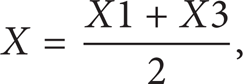
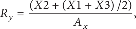
The worktable's real positions are X1, X2, X3, Y1, Y2, and Y3. Of them, X1 and X2 determine the worktable's displacement in parallel to X-axis and the rotation around Z-axis, and the mean of X1 and X2 together with X3 determines the worktable's rotation around Y-axis. Similarly, Y1 and Y2 determine the worktable's displacement in parallel to Y-axis and rotation around Z-axis, and the mean of Y1 and Y2 together with Y3 determines the worktable's rotation around X-axis. The worktable's position at time T1 can be expressed as (Figure 3)


3. Positioning Error Induced by the Time Difference in Multiaxial Measurement
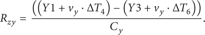
We suppose the worktable is moving at the speed of v x in X-phase and at v y in Y-phase. The data at 6 axes X1, X2, X3, Y1, Y2, and Y3 are collected via the traditional first-in first-out (FIFO) method. With time T1 as the sampling basis point, owing to the existence of data age, the data collected at T1 from X1 is actually the data at T1 − TDataAge. Since TDataAge is constant for each axis and consistent between axes, and the work-piece table's moving speed is known, then this problem during data processing can be solved via compensation. In the following part, the effect of TDataAge on positioning precision is not considered. The time differences of X2, X3, Y1, Y2, and Y3 at time T1 are ΔT2, ΔT3, ΔT4, ΔT5, and ΔT6, respectively. The worktable's position can be calculated as (Figure 3)


We suppose the worktable is moving at 1 m/s in parallel to X-axis. X1, X2, X3, Y1, Y2, and Y3 are adjacent successively when data are transmitted along the bus. We suppose that the single-axis data transmission along the bus takes 100 ns, or, namely, the sampling time difference between X1 and X3 is (200 ± Tp) ns, where Tp is the phase offset of the sampling clocks between X1 and X3. From (1) and (7), the worktable's positioning error in parallel to X-axis caused by asynchronous sampling is (100 ± Tp/2) nm.
Therefore, to build a mathematical model for precisely locating a moving worktable, the premise is to ensure the synchronization of sampling among all axes. In other words, the data age between a data sampling point and the basis sampling point for each axis should be consistent during laser measurement. The sampling age of an axis can also be understood as the time difference between the basis measuring time and the latch position information time. However, the data age when the laser interference signal is stored in the axial FIFO is unavoidable. The data ages of all axes are consistent and known. Thus, the data age inconsistency is caused by the time delay between the axial sampling time and basis sampling time, but this delay can be controlled. The worktable's ultra-precision motion control requires that the synchronization of interaxial delay error should be controlled at nanosecond scale. The interaxial sampling delay error will result in worktable positioning error and thus in failure of precision motion control.
4. Plan of Framework of Multiaxial Laser Displacement Measurement
A laser measurement channel composed of several laser measurement boards locates several worktables. To realize delay consistence between each axial data sampling point and the basis sampling point during multi-axial laser measurement, we should solve two problems. (1) The measurement data at each laser measuring axis should be latched and read by the bus simultaneously at the time of the basis sampling point; the data in boards’ FIFO should not be updated before all boards’ FIFOs are read. (2) The synchronous sampling signals of the laser measurement board should be “unified clock domain,” so as to reduce the interference of clock phase fluctuation.
In this paper, the latching function of the HP 10898A laser measurement board [11] was used to synchronously locate several laser axes. Based on “synchronized latch and sequential reading,” each laser axis’ position measuring data was synchrolatched at the basis sampling time. The real-time sampling data were read by a VME-P2 mouth, ensuring high reading rate and synchronized position sampling. The synchrolatching principally avoids sampling delay.
In this paper, a synchronized sampling method based on VME bus framework for multiple laser axes was used. Several HP 10898A laser measurement boards and one data acquisition board were installed in a VME case, whose framework is illustrated in Figure 4. The data acquisition board is the regulating and dispatching center that achieves the synchronized displacement sampling for multiple laser axes and the high-speed transmission of real-time data. Besides the synchronized sampling clock and the data latching control signal needed by all HP 10898A boards, this board also self-defines the bus’ real-time data reading instruction signal. The above framework ensures that all laser measurement boards are driven by the same synchronizing clock and the same data latching control signal, and the clock phase fluctuation only originates from the user-defined bus baseboard's electric signal transmission performance.

Framework of multiaxial laser displacement measurement.
A VME-P2 port which combines HP 10898A visiting sequences was used to latch and read laser data. When the data acquisition board sends out a direction of latch signal effective time at the basis sampling time, all laser position data are latched simultaneously (Figure 5). The transmission of position data at each laser axis is finished within each user-defined bus transmission cycle, while the corresponding position data are stored in the internal data buffer in the data acquisition board. Within a laser data sampling cycle which contains several cycles of user-defined bus transmission, all laser axes are latched and sequentially read simultaneously.
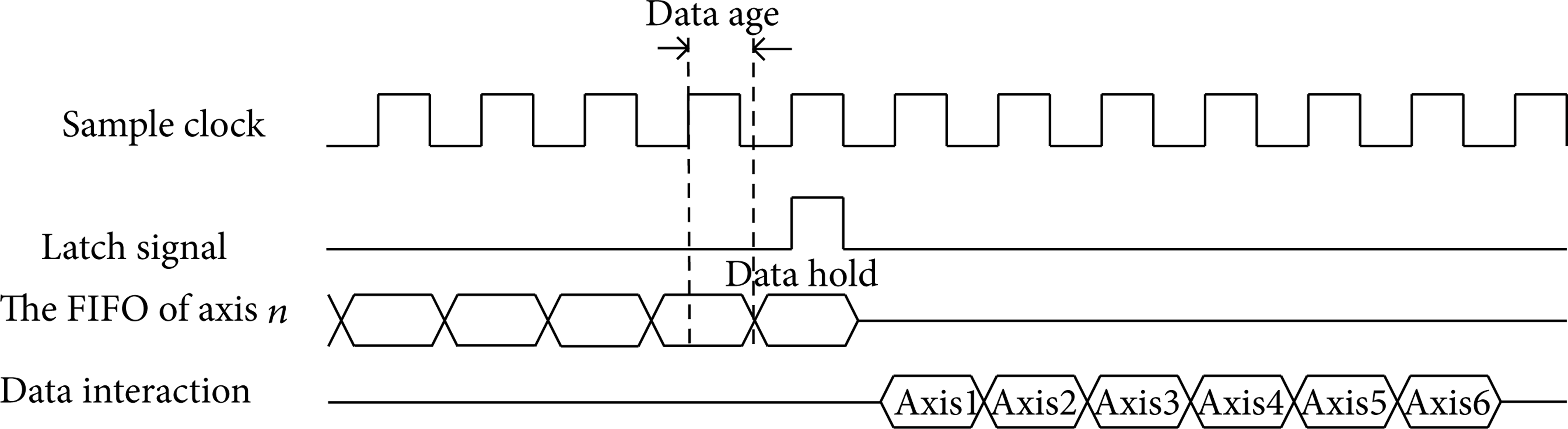
The sequence of measurement and sampling for 6 laser axes.
5. Errors in Synchronized Sampling and Measurement of Multiaxial Laser Displacement
The interaxial synchronized measuring time error originates from environmental uncertainty (e.g., air pressure, temperature, <1 ns) and from the signal phase fluctuation in the jointly used synchronized sampling clock [12]. The fixed internal data age of 1.062 μs in the HP 10898A board will not affect the synchronization of multiaxial sampling. The air pressure and temperature can be controlled in laboratory, and thus the uncontrollable interaxial sampling time error is mainly due to the delay between the synchronized sampling clock signal and the latch signal in the case of different slots, since the two signals are both transmitted in the VME-P2 bus, and their delay ages are equal for the same board.
A single HP 10898A board supplies two axes with laser interference measurement, and thus 3 HP 10898A boards are required by the 6 axes. The installation of the laser measurement boards and the data acquisition board is illustrated in Figure 6.

The installation of laser measurement board and data acquisition board in 6-axial laser measuring system.
Figure 7 compares the waveforms of synchronized trigger signals received by board 1 (a) and board 3 (b) separately with the synchronized starting signal sent from the data acquisition board. The errors of the former and the latter signal are 92 ps and 0.404 ns, respectively. This error will be linearly enlarged along with the increased installation distance between boards. This synchronized order error is due to the signal transmission delay in VME-P2 bus baseboard, and the clock signal phase error from different boards, but this error is always controlled at ns-scale.

Comparison of waveforms between the synchronized trigger signal received by board 1 (a) and board 3 (b); the synchronized starting signal sent from the data acquisition board.
Table 1 shows the numerical values of VME-P2 bus’ data transmission delay with different numbers of laser measurement boards and varying data transmission length. The major conclusions are as follows: (1) the synchronized latch trigger signal and the sampling clock's signal delay will be enhanced with the enlarged board installation distance, and the overall error does not exceed 0.8 ns (at a distance of 5 slots); (2) the 32-bit data line width of the synchronized user-defined bus in the laser measurement board's data transmission reaches a bandwidth of 320 Mbit/s, and the speed bottleneck lies in the baseboard's signal transmission properties; (3) the VME-P2 bus’ trigger signal delay is less than 0.03 ns when the system contains 2 laser counters and 5 laser measurement boards.
Data transmission delay in VME-P2 bus.

6. Conclusions
We first analyze the effects of moving multiaxial asynchronous sampling on the worktable's positioning precision and put forward a multiple laser synchronized measuring mechanism which satisfies the requirement for precise positioning of a moving worktable.
(1) We theoretically analyzed the key factors affecting the precise positioning of a moving worktable.
(2) We put forward a precise synchrone mechanism for multiaxial laser measurement: multiple laser measurement boards utilize the same sampling clock and the same latch signal, which ensures the consistency in sampling delay between all laser axes and ensures the strict synchronization in multiaxial sampling and latching.
(3) We built an experimental platform for testing. Tests showed that the maximum synchronized sampling time error from 6 laser measuring axes was 0.404 ns. When the table was moving at 1 m/s, the maximum displacement conversion error was 0.202 nm, which satisfied the strict nanosecond-scale requirement imposed by ultra-precise control for position measurement.
Footnotes
Nomenclature
Conflict of Interests
The authors declare that there is no conflict of interests regarding the publication of this paper.
Authors’ Contribution
Rou-gang Zhou and Guang-Dou Liu contributed equally to this work.
Acknowledgments
This research was supported by National Natural Science Foundation of China (Project nos. 51375194 and 51375196) and State Key Lab of Digital Manufacturing Equipment & Technology, School of Mechanical Science and Engineering, Huazhong University of Science & Technology.