
Abstract
In specific industrial applications like very thin-walled aeronautical structures or turbine blades, workpiece vibration is strongly dominant in comparison with spindle-tool set vibration. A method for predicting the dynamic stable lobe diagram (DSLD) of thin-walled component peripheral milling process is proposed, which takes into account the variations of dynamic characteristics of workpiece with the tool position. A specific DSLD is elaborated by scanning the dynamic properties of workpiece along the machined direction throughout the machining process. And, based on the results of stability prediction for thin-walled component milling, influences of chatter on machining distortion (including cutting distortion and secular distortion) are investigated through specifying cutting conditions. Then these results are compared and verified by milling experiments.
1. Introduction
High-speed milling technology is being widely used in many different fields, such as aeronautics and astronautics, automobile, and die and mould [1]; in particular it is used in high-speed machining aeronautical monolithic components. In the milling process of monolithic components, large machining distortions are often observed [2]. With increasing of machining velocity, chatter vibration [3] due to the dynamic interactions between tool and workpiece is one of the most common detrimental phenomena and major obstruction toward achieving automation, higher productivity, and better surface finish and also plays an important role on machining distortion. Chatter vibration due to the dynamic interactions between tool and workpiece has been widely studied in the past century since Taylor first identified and described chatter in 1907. All these studies [3–6] have led to graphic charts showing the stability information as a function of chip thickness and spindle speed. And the assumption was made that the dynamic characteristics of system did not change during the whole machining processes.
The focus of many recent works has been the phenomenon that the dynamic characteristics of thin-walled workpiece are changed during the whole machining processes. Bravo et al. [7] proposed considering such applications and suggested a method for obtaining a 3D stability lobe to cover all the intermediate machining stages. Thevenot et al. [8] introduced the dynamical behavior variation of the part with respect to the tool position in order to determine optimal cutting condition during the machining process and constructed a 3D stability lobe diagram. Song et al. [9] proposed a method for predicting simultaneous dynamic stability limit of thin-walled workpiece high-speed milling process. On the other hand, machining distortion is a very complicated problem in high-speed machining thin-walled workpiece. Many investigations have been reported in journals. Guo et al. [10] predicted the milling distortion for aero-multi-frame parts. Bi et al. [11] established a model to predict the distortion of aerospace monolithic components using 3D finite element method. Tang et al. [12], Dong and Ke [13], and Wang et al. [14] investigated the residual stresses induced by milling aluminum alloy. Zhang et al. [15] proposed a straightening technique for distorted aeronautical monolithic component based on finite element numerical simulation. However, most of the investigations about distortion are based on the assumption of static process. Instantaneous factors in machining process, such as vibration, are not considered.
The present work is undertaken to describe a method for predicting simultaneous dynamic stability lobe diagram (DSLD) of thin-walled workpiece high-speed milling process assuming a rigid spindle-tool set. And, based on the stability analytical results, influences of chatter on machining distortion are also investigated in detail.
2. Dynamic Model
2.1. Equation of Motion
The thin-walled workpiece can be considered to have a degree of freedom as shown in y direction assuming a rigid spindle-tool set, as shown in Figure 1. The symbol a e is the radial depth of cut, and Ω is the constant rotational angular velocity (rad/s). Cutting forces excite the structure, causing dynamic displacement y of cutter in the normal (y) direction. The instantaneous chip thickness reads

where y(t − τ) and y(t) are the vibration displacements of the previous tooth and the current tooth. τ is time delay; τ = 2π/(NΩ). N is the number of teeth. φ i (t) is the location of the ith tooth:

The instantaneous cutting force is proportion to the instantaneous chip thickness:

where a p is the axial depth of cut. d(t) is the specific cutting force factor:

where d(t) is τ periodic; that is, d(t) = d(t + τ). K t and K r are the tangential and radial cutting coefficients, respectively. δ i (φ i (t)) is a Heaviside step function that assumes a value one when the cutting tooth is engaged in cutting process and zero when the tool is out of the cut:

where φen and φex are enter angle and exit angle for tooth, respectively.

Milling model for thin-walled workpiece.
The corresponding governing equation has the form [9]
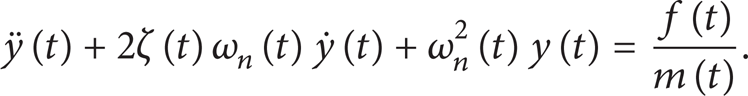
Equation (6) is a linear periodic delay differential equation (DDE) with time-variable parameters.
2.2. Workpiece Dynamic according to Tool Position
The typical thin-walled workpiece is made from aeronautical aluminum alloy (7050), with physical properties: Young's modulus of elasticity E = 70.3 GPa, density ρ = 2,820 kg/m3, and Poisson's ratio μ = 0.33. The thin wall was down-milled in finishing with axial depth of cut 5 mm, radial immersion of 0.6 mm, and feed rate of 0.1 mm/tooth. The workpiece dimensions chosen for the study are a rectangular prism of 100 × 30 × 3 mm with a thin wall of 3 mm thickness and 30 mm height that can be found easily in the industry, for example, an inner pocket wall. The workpiece dynamic equations are established using a reduction of the FEM to specific master degrees of freedom using the Guyan algorithm. The workpiece is divided into 21 equidistant points, enabling an accurate workpiece dynamic prediction to be made throughout the machining process. Because machining system is a lightly damped structure, it is assumed that the damping ratio of the workpiece does not change depending on tool position over the cutting process. And the damping ratio of the workpiece is obtained from the initial state of the workpiece.
3. Experiments Analysis
There are four different types of experiments conducted in this paper. The machining centre used is a vertical CNC milling machine (DMU-70V) with a spindle that can rotate up to 18,000 rpm.
Dynamic Tests. The motivation of dynamic tests is to obtain the initial experimental modal characteristic of the workpiece in order to adjust the FEM results to the real behavior of the part. A series of conventional impact hammer tests are performed. To excite the structure with the thin-walled structure, a miniature impact hammer (LC-01A) is employed. The deflection is measured using three eddy current displacement sensors, which may effectively measure micromovements lower than 10 μm, as shown in Figure 2. The data is collected through CRAS data acquisition software supported by the CRAS corporation. And the collected data is analyzed by MATLAB toolbox, which contains an embedded antialiasing filter that prevents the data to be contaminated by the very high frequency noise. The initial modal parameters of workpiece are listed in Table 1.
Initial modal parameters of workpiece and cutting coefficients.


Experimental setup.
Cutting Tests. The cutting tests are carried on to identify the cutting constants. A set of experiments is performed on DMU-70V. A table Kistler dynamometer is used to accurately measure the cutting forces. The data were acquired using a data acquisition system (Dynwave Type 2825D-02). The root mean square (RMS) of the forces was employed. The mechanistic cutting coefficients are shown in Table 1.
Chatter Tests. To valid the stability results, down-milling experiments without coolant were performed with selected cutting parameters, feed per tooth 0.1 mm, axial depth of cut 5 mm, radial depth of cut 0.6 mm, and the spindle speeds 14,000 rpm (Case I), 15,000 rpm (Case II), and 16,000 rpm (Case III), respectively. Solid carbide cutter with 12 mm of diameter and 30-degree helix angle (three flutes) was selected. Before the chatter tests, the workpiece surface was flatted.
Machining Distortion Tests. The two sample parts (“A” and “B”) with 280 mm × 80 mm × 40 mm are selected in milling experiments, as shown in Figure 3. The cutter is solid carbide end mill with 3 flutes, 20 mm diameter, and 30-degree helix angle. All milling tests are conducted in the same condition, such as machining center, cutter, cutter material, geometry of cutter, workpiece material, and fixture. In the first, the top and bottom surfaces of sample parts are flattened by using face mill (blade material is YG8X) with 100 mm diameter.

Sample parts used in milling experiments.
Then, the thickness of sample parts is measured by using the MISTRAL 775 coordinate measuring machine (CMM) and named as δA1 and δB1. The measured locations are 2 mm, 20 mm, 40 mm, 60 mm, and 78 mm in y direction, respectively, and one sample point each 10 mm in x direction. The total number of sample points is 145. Based on the stability results for the sample parts milling process, two cutting cases are selected: one is that rotating speed is 16,000 rpm (stable case); the other is that rotating speed is 12,000 rpm (unstable). Other cutting conditions are as follows: radial depth of cut is 1 mm, axial depth of cut is 10 mm, feed per tooth is 0.1 mm, and it is down-milling without cutting fluid. During the cutting tests, two sample parts are applied using the same fixed conditions, respectively.
When it is 0 hours and 170 hours after machining, the thickness of sample parts is remeasured by using the MISTRAL 775 CMM and named as δA2, δB2 and δA3, δB3, respectively. Measured origins of three times are the same in order to keep the uniqueness of measured coordinates. Finally, the differences between three measured results (δA1 − δA2, δB1 − δB2, δA2 − δA3, and δB2 − δB3) are machining distortion (ΔδA and ΔδB) and time-dependent distortion (ΔδA′ and ΔδB′), respectively.
4. Results and Discussions
4.1. FRF of Workpiece Depending on the Tool Position
Without loss of generality, one cutting process (a e is 5 mm, a p is 0.6 mm, length of workpiece (x direction) is 100 mm, and thickness is 3 mm) of workpiece is discreted. By using the transform function theory and the least-squares method, the first modal natural frequency is expressed as [9]

The other modal parameters are also calculated in the same way.
4.2. 3D DSLD for Thin-Walled Workpiece Milling
The 3D DSLD of thin-walled workpiece milling is determined for different spindle speeds and different tool positions by the numerical method, as shown in Figure 4. The zones in the upper curved surface are unstable, and the zones under the curved surface are stable.

Three-dimensional stability chart of thin-walled workpiece.
It can be seen that the graphic charts only determined by the “spindle speed” axis and “axial depth of cut” axis express the traditional stability lobes proposed in [3–6]. It is assumed that the dynamic characteristics of system did not change during the whole machining processes. While, when the material removal is significant, the dynamic properties (natural frequencies, mainly) of the workpiece change according to the tool position. Thus, the 3D DSLD includes the variation of the dynamic parameters of the workpiece in third dimension of the stability lobes.
On the other hand, the graphic charts only determined by the “tool position” axis and “axial depth of cut” axis express the new stability lobes, which includes the variation of the dynamic parameters of the workpiece with a fixed spindle speed. Without loss of generality, three different spindle speeds (e.g. 14,000 rpm (Case I), 15,000 rpm (Case II), and 16,000 rpm (Case III)) are selected. The DSLDs for these spindle speeds are shown in Figure 5. In Figure 5, the zones above the curves are unstable, and the zones under the curves are stable. It can be seen that the variation of the natural frequencies of the workpiece during machining introduces a shift of the lobes along the spindle speed axis. Consequently, if this shift is rather significant, it is possible that no stable spindle speed exists throughout the machining process, for example, Case III in Figure 5. Then, the spindle speed must be adjusted during machining in order to achieve a stable behavior of the workpiece.
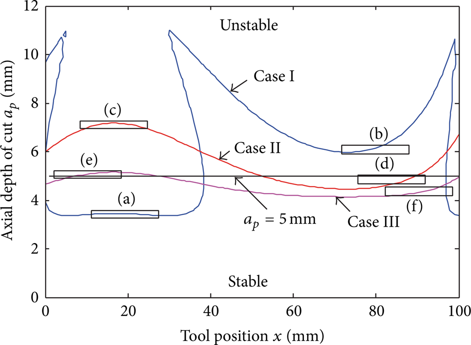
Stable axial depth of cut depending on tool position. Case I: 14,000 rpm; Case II: 15,000 rpm; Case III: 16,000 rpm.
4.3. Chatter Tests for Thin-Walled Workpiece Milling
Figure 6 is the photograph of machined workpiece. In Figure 6, the regions labeled (a)–(f) are in accordance with those in Figure 5. Comparing between Figures 5 and 6, the well agreements can be observed between experimental results and numerical results. For milling process in 14,000 rpm case, the first half (e.g., (a) in Figure 5) of the cutting process is unstable, and the cutting force is very large, while the second half process (e.g., (b) in Figure 5) is stable. The results are also confirmed by the experimental photographs in Figure 7. For the case 15,000 rpm, it is contrary to the case of 14,000 rpm, the first half part is stable, and the rest part is unstable. The whole process for the case 16,000 rpm is almost unstable, and the surface finish of machined workpiece is also very poor.

Photographs of machined workpiece.

Photographs of machined workpiece surfaces in different cutting conditions.
4.4. Machining Distortion Tests for Monolithic Components
Figure 7 shows the photographs of machined workpiece surfaces; (a) is obtained in stable cutting condition, and (b) is obtained in unstable cutting condition. It can be seen that, in unstable cutting condition, workpiece surface has significant chattermark, and the surface quality is very poor.
Figure 8 shows the machining distortion and time-dependent distortion in stable cutting condition. In Figure 8, it can be seen that two kinds of distortions are both very little. The maximum value of distortions is lower than 10 μm.

Maps of machining distortion and time-dependent distortion in stable cutting condition.
Figure 9 shows the machining distortion and time-dependent distortion in unstable cutting condition. In Figure 9, similar to the results in stable cutting condition, the machining distortion is also very little, and the maximum value is lower than 6 μm. While the time-dependent distortion is very large, the maximum value of distortions is larger than 12 μm, and torsion occurs in the side of sample part with larger box (weaker stiffness).
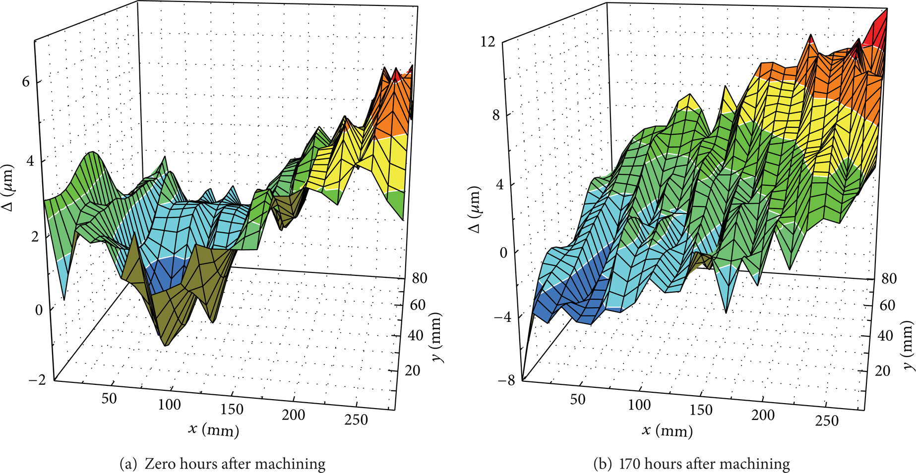
Maps of machining distortion and time-dependent distortion in unstable cutting condition.
It is shown that (1) both the cutting distortion and time-dependent distortion are very little in stable cutting conditions; (2) in unstable cutting conditions, the cutting distortion is very little, while time-dependent distortion is very large, and the torsion appears in the side of sample part with weaker stiffness; (3) chatter plays an important part in the distortion. In unstable cutting conditions, cutting distortion is very little and does not change with time, while time-dependent distortion is very large and changes with time. Therefore, machining operation had better conduct in stable cutting conditions in order to assemble easily.
The dynamic interaction between tool and workpiece is one of the most common detrimental phenomena in high-speed machining processes. In general, machining distortion can be caused by the residual stress, which mainly includes two components: the first is the residual stress induced machining process and the second is the one induced earlier in material processing. In fact, the residual stress induced machining process is concerned with cutting force and cutting temperature. As we know, cutting force can be divided into static and dynamic forces. And the dynamic force results in vibration stress in the surface layer of workpiece. Therefore, in the different cutting conditions given in the above section, different machining distortions arise. The essential reason may be that vibration stress is different for several cutting conditions.
5. Conclusions
A method for predicting the DSLD of thin-walled workpiece milling process is described. The proposed approach takes into account the variations of dynamic characteristics of workpiece with the tool position. A specific DSLD is then elaborated by scanning the dynamic properties of workpiece along the machined direction throughout the machining process.
Based on the results of stability prediction for thin-walled workpiece milling, influences of chatter on machining distortion are investigated. It is shown that (1) both the cutting distortion and time-dependent distortion are very little in stable cutting conditions; (2) in unstable cutting conditions, the cutting distortion is very little, while time-dependent distortion is very large, and the torsion appears in the side of sample part with weaker stiffness; (3) chatter plays an important part in the distortion. In unstable cutting conditions, cutting distortion is very little and does not change with time, while time-dependent distortion is very large and changes with time.
Conflict of Interests
The authors declare that there is no conflict of interests regarding the publication of this paper.
Footnotes
Acknowledgments
The authors are grateful to the financial supports of the National Natural Science Foundation of China (no. 51205233), the Research Award fund for Outstanding Young Scientists of Shandong Province (no. BS2013ZZ013), and Major National Science and Technology Project (no. 2014ZX04012-014).