
Abstract
Wireless Sensor Network (WSN) has been considered as a promising solution for Smart Grid due to the significant advantages over traditional communication technologies. However, as a necessary function for monitoring, diagnosing, and controlling of remote electrical equipment, Quality of Service (QoS) is still a challenging problem in applying WSN in Smart Grid. This paper presents a comprehensive experimental study on optimization of multiobject QoS in cross-layers of WSN protocol. In PHY layer, a Link Quality Estimator is studied for the purpose of evaluating link quality under harsh Smart Grid environments. In MAC layer, a QoS Enhanced MAC algorithm is used to prevent disorderly contentions among nodes and to allocate more channel resources for critical traffic; in NWK layer, a routing algorithm is introduced for multiobject QoS optimization. All the algorithms are cooperated with each other in cross-layer manner to improve end-to-end reliability and latency. In comparison with other counterparts, the proposed algorithms achieve preferable performances. Finally, field experiments were conducted, the result of which showed that the proposed algorithms outperform the ZigBee protocol and the original Distribution Grid wireless communication technology in terms of the QoS performance of critical traffic.
1. Introduction
With the features of rapid self-organizing and superior coordinating ability, Wireless Sensor Network (WSN) has a wide application prospect in the field of remote supervisory control and fault diagnosis for Smart Grid. In 2012, WSN was listed as the future Home Area Network of Smart Grid by NIST [1]. And in the same year, IEEE published IEEE802.15.4g Low-Data-Rate Smart Metering Utility Networks standard in local and metropolitan area networks [2].
Recent advances of WSN in Smart Grid make it feasible to conduct the embedded electric utility monitoring and communicating. However, there are still some challenges in applying WSN in Smart Grid, such as harsh environmental conditions, reliability and latency requirements, packet errors and variable link capacity, and resource constraints [3]. Recent researches [4–8] mainly concentrated on the application of WSN in electrical power grid. However, an overlooked question is the analysis of varied quality of service (QoS) requirements for diversified communication traffics under complex environments. Since IEEE802.15.4 standard does not support QoS, several studies [9, 10] were conducted to provide QoS for WSN. However, some uncertain interference factors on wireless link in harsh environment were not taken into account.
As a matter of fact, with limited resources and lower boundary requirements, the study of WSN-based Smart Grid application should resolve the multiobjective (reliability and latency) end-to-end QoS optimization problems in multihop transmission with uncertain processes. To achieve the goal, a comprehensive experimental study on cross-layer based multiobjective QoS optimization was carried out in Smart Grid communication. This study sets two different classes of Smart Grid communication packets in cross-layer optimization by their reliability and latency QoS requirements. All the algorithms were implemented in three layers of WSN protocol, namely, physical (PHY) layer, media access control (MAC) layer and network (NWK) layer. First, a link quality estimator (LQE) was introduced to evaluate link quality under harsh environments. Then, a QoS enhanced MAC (QoS-MAC) algorithm was used to avoid disorderly contention among WSN nodes and to effectively allocate limited wireless channel resources to two classes of packets. Lastly, reliability and latency estimators were designed to provide estimation information for link quality routing (LQ-routing) algorithm, which optimized the multiobject end-to-end QoS performance in the multihop transmission. Figure 1 shows the cross-layer QoS optimization framework, in which IEEE802.15.4-based WSN is adopted.

Cross-layer QoS optimization framework of WSN.
The rest of this paper is organized as follows. Section 2 introduces the related works. Section 3 presents the analysis of the affecting factors on link quality and the LQE for evaluating link quality in harsh Smart Grid environments. Sections 4 and 5 discuss the enhancement of QoS in MAC layer and NWK layer by the proposed QoS-MAC algorithm and LQ-routing algorithm, respectively. Section 6 explains the field experiments conducted to verify the proposed cross-layer QoS optimization of WSN. Lastly, Section 7 is the conclusion of the paper.
2. Related Works
This section introduces relevant existing works on WSN from the perspectives of link quality estimator, QoS-based MAC protocols, QoS-based routing optimization and QoS-based optimization of WSNs for Smart Grid.
2.1. Link Quality Estimator
LQE, as a way of evaluating media channel of WSN, has triggered a comprehensive study [11]. In general, LQEs can be classified as either hardware-based or software-based.
Received signal strength indicator (RSSI) and link quality indicator (LQI) are common metrics of hardware-based LQEs, which can be directly read from hardware registers of transceiver. It takes them much less time to estimate link quality than software-based counterparts. However, RSSI and LQI are acquired based on part samples of a successfully received packet, which cannot reflect link quality status when the packet is lost [12–14]. Besides, they have no clear-cut relation with link quality status. Although packet reception ratio (PRR) can be theoretically computed by SNR [11], many popular IEEE802.15.4-compatibility chips (e.g., CC25XX, EM35X) do not provide SNR value. In addition, hardware-based LQEs are easily affected by the quality of transceiver hardware circuit, the directivity of antenna, and environmental factors.
PRR and RNP (required number of packets) are basic metrics of software-based LQEs. PRR is defined as ratio of the number of successfully received packets to all transmitted packets in receiver side, while RNP is defined as the ratio of the number of transmitted and retransmitted packets to the number of successfully received packets, minus 1, in sender side [15]. Expected transmission count (ETX) [16] is another software-based LQE, which is evaluated by both forward and backward PRR values. Those three software-based LQE metrics can better reflect the condition of wireless communication links. However, the estimation processes of software-based LQEs usually take additive latency to collect enough statistical information in improving estimation accuracy, which may be worse when the link quality fluctuates. To address this problem, window mean with exponentially weighted moving average (WMEWMA) [17], Kalman filter [18], Fuzzy Logic [19], and so forth, are adopted to estimate link quality metrics. However, in practice, Kalman filter and Fuzzy Logic are complex and require important storage resources. WMEWMA has the advantage of less complexity in computation, less storage spaces and faster response ability. It not only takes the past link quality status into account, but also reflects the rapid changes of estimation object, which means it is more suitable for WSN devices with limited computation capability.
The reliability requirements of Smart Grid communication are usually evaluated by packet success rate (which equals PRR), as a result of which, PRR is a more intuitional metric than its hardware-based and software-based counterparts for the algorithms of upper layer protocol. In this study, PRR is selected as the metric of LQE. Besides, WMEWMA is adopted to estimate link quality and to balance the performances of accuracy and the efficiency of estimation results in [17]. But the LQE in this study is executed in sender side; thus the overhead of sending back estimation result could be avoided.
2.2. QoS-Based MAC Algorithm
MAC protocol provides channel access control mechanisms, which makes it possible for nodes to communicate within WSN incorporating a shared medium. In general, QoS MAC protocols can be classified as schedule-based or contention-based protocols.
Time division multiple access (TDMA) algorithm [20–23] is mostly adopted for schedule-based MAC protocol. In TDMA algorithm, the access is divided into different time slots for nodes. Each node accesses media channel at its own time slot to avoid collision and to bring controllable transfer delay. Although TDMA protocols are advantageous in collision-free medium access, they suffer heavily from the following problems, such as clock synchronization, channel under-utilization, and fixed time-slot assignments [24]. Rate allocation algorithms [25–28] are another schedule-based MAC protocol, which assigns different rates to users on demand in optimizing the communication delay. However, it requires abundant information exchange, which visibly increases the complexity of protocol and additional overhead to achieve QoS in MAC.
Unlike schedule-based algorithm, contention-based QoS MAC protocols access media channel in a random contention manner. Several subsequent studies based on S-MAC [29, 30] adopt duty-cycling mechanism (synchronous sleep and wakeup for communication) with the aim of balancing the transfer delay and energy consumption in WSN. However, the periodical sleep-and-wakeup would result in significant latency. Furthermore, the nodes maintaining synchronous sleep and wakeup also increase additional overhead as TDMA algorithm. Sleepless random access MAC protocols allow the obtaining of significant QoS performance in comparison with duty-cycling [31]. The sleepless feature makes the protocol more energy-consuming, while, in Smart Grid, energy can be acquired from low-voltage equipment, which make it more appropriate compared with sleep-and-wakeup MAC. However, the random contention feature of CSMA/CA in sleepless mode of IEEE802.15.4 standard would lead to more or less influence in the performance of critical traffic by other regular traffics.
In this paper, a novel QoS-MAC is explored by introducing unfair contention among nodes. The QoS-MAC is aimed at maximizing the utilization of media channel and reducing the contention influence on critical traffic. Besides, the proposed MAC algorithm can be operated in the distribution way with no additional overhead.
2.3. QoS Based Routing Protocol
Routing is a key technology in achieving multihop transmission in WSN. Many routing solutions, including negotiation-based routing [32], query-based routing [33], location-based routing [34], multi-path-based routing, and ant-based routing [35] are proposed in WSN to balance the predetermined QoS metrics, such as delay, energy, reliability, and bandwidth, before delivering the data to the sink node [36]. Of those routing protocols, location-based routing protocols, which use localization information to select the next router from neighboring nodes geographically closer to the destination [37], are efficient in networks with stationary nodes. Therefore, location-based routing algorithm is suitable for Smart Grid application, as the geographical position of electrical equipment and utilities is known and almost immobile.
A lot of efforts, for example, SPEED [38] and MMSPEED [39] et al., are made to support QoS on location-based routing. In SPEED routing protocol, each node keeps the geographic information of its immediate neighbor to make routing decision. SPEED is designed to transmit packets through routes at a given speed to reduce delay. However, SPEED does not consider another QoS metric, reliability. MMSPEED attempts to improve SPEED by multispeed routing according to the delay requirement of packets when providing reliability QoS by multipath routing. MCMP [40] is another location-based routing protocol, which aims to provide multiconstrained QoS for different packets as path information is not readily available in wireless networks. MCMP utilizes multiple paths between sources and sink pairs for QoS provisioning. However, multipath routing may reduce the throughput of network. What is more; packets may be highly congested nodes near to sink. To prevent such congestion, LOCALMOR protocol [41] addresses reliability, namely, single-path multiple sink by a different approach, which increases sink nodes to reduce congestion. Moreover, link reliability and latency estimators are considered in the routing metrics. As a matter of fact, LOCALMOR reduces the range collected by a sink node.
All the location-based protocols mentioned above do not distinguish the different requirements of application traffic. The information of MAC layer and PHY layer are not both considered in routing decision. In this study, reliability estimator and latency estimator are introduced to provide cross-layer information required. Then a routing algorithm named LQ-routing is presented for multiconstrained QoS optimization to improve the performance of reliability and latency for critical Smart Grid traffic.
2.4. QoS Based Optimization of WSNs for Smart Grid
Various traffics of Smart Grid have different QoS requirements on communication latency and reliability. Ericsson classified the communication of Smart Grid into 3 types (real-time operational, administrative operational, and administrative communications) with different QoS requirements [42]. Detailed latency and reliability requirements of Smart Grid applications presented in Table 1 [43] are different with each other as well. Therefore, satisfying the QoS requirements is one of major technical challenges of WSNs in Smart Grid applications.
Smart Grid applications and their QoS requirements.

Many WSN-based Smart Grid studies like [6–8] are concerned with applications, but they neglect the fact that the IEEE802.15.4 standard of WSN is without QoS scheme.
In literature, some QoS optimization studies are carried out with the aim to provide QoS for Smart Grid in layered WSN protocols. For MAC layer, a MAC algorithm is presented in [44] to add the QoS to WSN protocols by providing differentiated service for Smart Grid traffic of different priorities. Two medium-access approaches, namely, DRX and FDRX data transmission, are introduced in [45] to deal with the delay and service requirements of Smart Grid. For NWK layer, the well-known on-demand, table-driven, and QoS-aware routing protocols are investigated in [46] in terms of packet delivery ratio, end-to-end delay, and energy consumption to show the advantages and disadvantages of each routing protocol type in different Smart Grid spectrum environments. Multipath and single-path QoS-aware routing algorithms are investigated in [47] to evaluate their service differentiation capabilities in reliability and timeliness domains under harsh Smart Grid environmental conditions.
The above layered QoS studies [44–47] try to improve and analyze the adaptability and performance of WSN in Smart Grid application. However, optimization in a layer does not represent the best solution for the entire WSN protocol stack. Consequently, cross-layer QoS optimization becomes increasingly important. A recent cross-layer study for Smart Grid [45] is mainly focused on spectrum access in Cognitive Radio Sensor Networks for Smart Grid. However, it does not explore the end-to-end performance of media access and multihop routing.
Therefore, in this paper, we aim to introduce a cross-layer optimization in PHY, MAC, and NWK layer protocols to provide a better end-to-end QoS performance for multihop WSN in Smart Grid.
3. Wireless Link Quality Evaluation in PHY Layer
In this section, we first analyze the affecting factors on Link Quality metric PRR. Then an LQE is presented to evaluate link quality between neighbor nodes.
3.1. Affecting Factors on Link Quality in Smart Grid
In IEEE802.15.4 based WSN, OQPSK modulation is employed by PHY layer. The bit error rate (BER) of OQPSK can be calculated as [48]

where

where
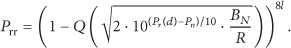
In order to verify integrity of packet, CRC (cyclic redundancy check) is adopted in IEEE802.15.4. An error may lead to the failure of packet reception. Therefore, the packet reception rate can be calculated as

where l is the packet size in byte.
Consequently, theoretical Link Quality model can be expressed as (4), which is derived by inserting (1) and (2) into (3):
As a whole, the affecting factors on Link Quality are the background noise
3.1.1. Background Noise in Smart Grid Environments
The noise interfering with WSN communication may be derived from background noise of environment and the interference of other WSN nodes. To measure background noise in Smart Grid environment, only one CC2530 based WSN node that is working in receive energy scan mode is used to avoid interference from other homogenous nodes. The measured channel is set as the 26th channel of IEEE802.15.4 to avoid interference from WiFi devices, since the 26th channel does not overlap with IEEE802.11 channel. The background sampling interval is 20 ms, and the background sampling result is the maximum received energy value in sampling duration of 0.2 ms. Figure 2 shows three kinds of Smart Grid environments, where background noise is measured by CC2530 based WSN node. Figures 3(a), 3(b), and 3(c) present Background Noise samples in the respective Smart Grid environments. The bar charts in Figures 3(d), 3(e), and 3(f) express corresponding relative frequency (RF) of the measured background noise energy in three Smart Grid environments. Background noise in Smart Grid environments fluctuates rapidly with kind of impulse features. It may be increased by 10–20 dBm with low relative frequency. Measured energy of background noise beside distribution lines is greater than that of other 2 environments about 2 dBm, which may result in the reducing of SNR by 1.5 times computed by (2).

Smart Grid environments of experiments. (a) Distribution line, (b) substation, (c) residence area.

Background noise samples and corresponding relative frequency in three Smart Grid environments.
3.1.2. Received Signal Strength in Smart Grid Environments
By log-distance path loss model, received signal strength can be expressed as
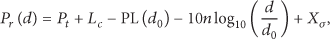
where
We use a pair of CC2530 based WSN nodes to estimate the actual power loss
Estimated parameters of signal strength in Smart Grid environments.

In Table 2, the estimated hardware-related actual power loss
It can be concluded by the experiment and analysis above that the Background Noise and received signal strength are mainly affected by different factors in Smart Grid environment, when the WSN node is homogeneous. Furthermore, Link Quality varies dramatically in accordance with changes in environments. This observation justifies the need of LQE for QoS Optimization in WSN based Smart Grid.
3.2. Link Quality Estimator
In our LQE, PRR is used as the metric of Link Quality.

The selected value of
After transmitting

where
Different from PRR of LQE introduced in [15], the LQE is computed in sender side, which can be used to reduce the overhead of exchanging link quality information among nodes.
4. Quality of Service in MAC Layer
Smart Grid traffics require that WSN's MAC Protocol provides QoS with latency bounds for various traffics, which means that the node sending critical packet should preferentially access media channel. It is important to guarantee the reporting time within a given bound even in the worst case. This section presents a novel QoS-enhanced MAC for IEEE802.15.4. The QoS-MAC protocol provides differentiated services for data traffic with varied priorities.
4.1. CSMA/CA of IEEE802.15.4
IEEE802.15.4 MAC layer protocol supports two medium access modes: the slotted mode (beacon-enable mode) and unslotted mode (nonbeacon-enable mode) [49]. In the slotted mode, the MAC layer accesses the medium by a beacon-based superframe structure. The superframe is divided into active and inactive periods. During an inactive period, the node turns off the device radio and then sleeps in order to save energy. In the unslotted mode, arbitration of medium access is achieved by the CSMA/CA scheme [49], since nodes never sleep. The unslotted CSMA/CA flow chart is shown in Figure 4.
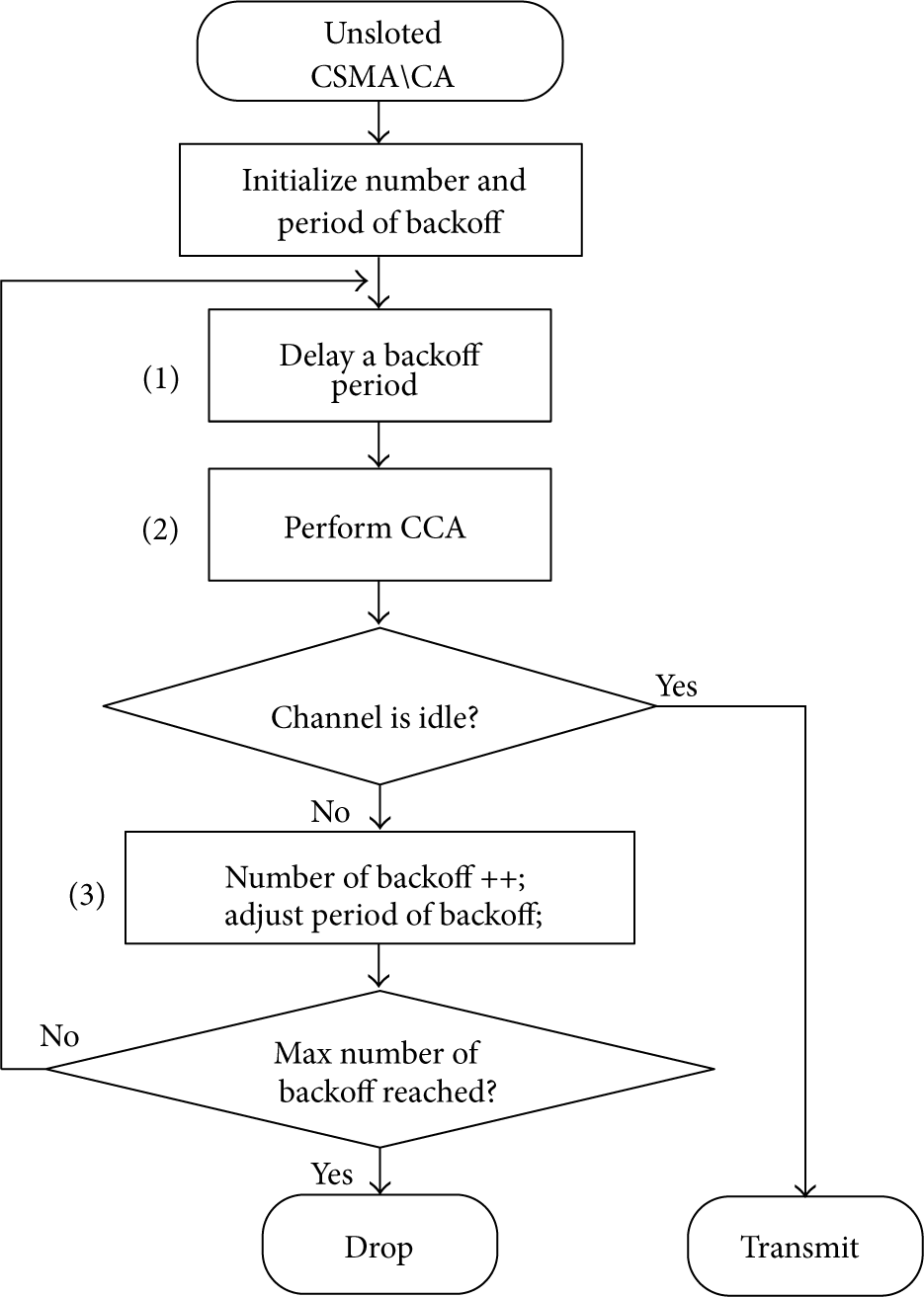
Unslotted CSMA/CA flow chart of IEEE802.15.4.
When there is a packet needing to be transmitted, node starts CSMA/CA by initializing number and period backoff. Then it delays a backoff period and performs CCA (clear channel assessment). If channel is idle, the node starts to transmit the packet, otherwise, it would adjust backoff period and restart it until it reaches the max number of backoffs. If max number of backoffs is reached and the channel is still busy, the packet will be dropped.
4.2. QoS-MAC Algorithm
In our QoS-MAC, the data packets will be buffered in the two queues based on their requirements for timely delivery: the critical traffic, considered as high priority (HP) packets (require immediate delivery with guaranteed delay and delivery rate), is pushed into HP queue; the regular traffic, considered as low priority (LP) packets (which typically have more tolerance in network delay and delivery rate), is pushed into LP queue.
Our QoS-MAC algorithm has three rules, one for competition within the node, and the other two for competition within a network among different nodes.
Rule 1.
For CSMA/CA mechanism in the node, any packets in the LP queue will not be serviced if the queue of the HP packets is not empty.
Rule 2.
When competing with each other for channel access in a network, the nodes with HP packets have fixed short backoff period, more backoffs, and more frequent CCA detection, while the nodes with LP packet use long random backoff period, less backoffs, and less frequent CCA detection.
Rule 3.
In CSMA/CA, CCA detection time of node sending HP packet is short, meanwhile CCA detection time of node sending LP packet is longer than the sum of backoff periods and CCA detection time of node sending HP packet.
These CSMA/CA rules are simple enough to be embedded into any network stack without additional expenses (i.e., overhead). Figure 5 shows the time frame of four nodes contending the channel access during the same period. Assuming that Node 1 and Node 2 have HP packets to be sent while Node 3 and Node 4 only have LP packets to be sent. At the beginning of the time fragment, Node 3 occupies the medium, later Node 1 and Node 2 receive their HP packets and start to service them. After they detect that the channel is busy, their CSMA/CA initiates the backoff period. At time 0, Node 3 completes its transmission and releases the channel for contention and automatically begins backoff for its next LP packet if there is any. During time slots 0 and 1, although Node 4 started its CCA detection first, Node 1 has shorter CCA detection interval because it has HP packets to be sent (Rule 2). Though Node 2 also has HP packets to be sent, its CCA finished before Node 3 releases the channel. Hence, at time 1, Node 1 starts its transmission of HP packets by interrupting the service of Node 4 (sending LP packets), which is forced by another backoff period after its CCA detection ends.
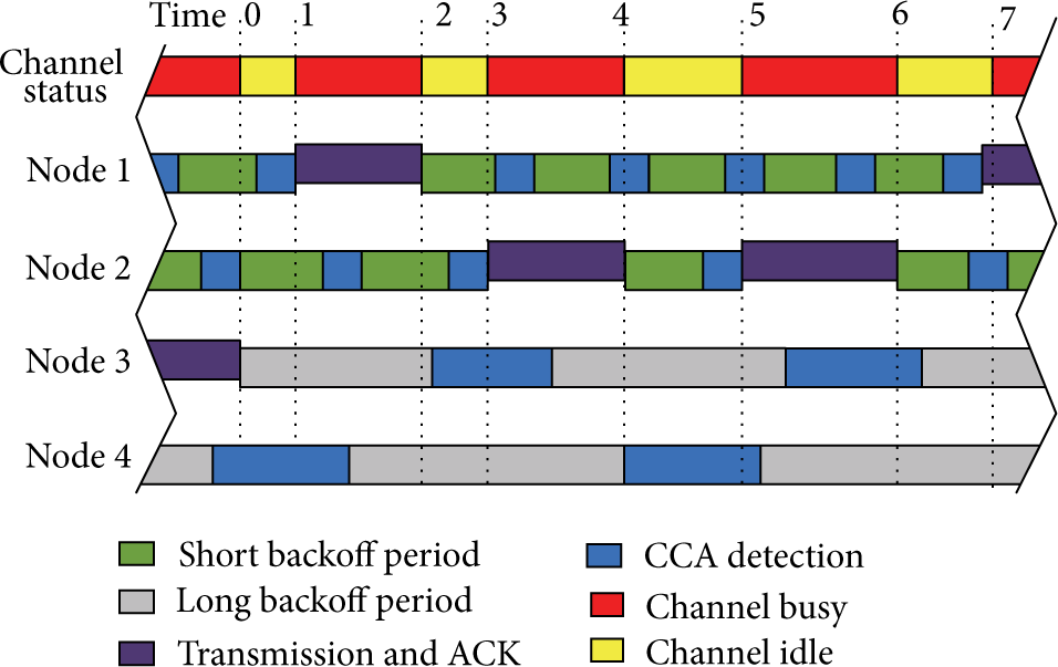
Nodes channel access competitive timing diagram.
At time 2 Node 1 finishes transmission and releases the channel before starting its short backoff time. In this case, Node 2 acquires the right to use wireless channel since Node 3 has not yet finished its CCA detection time (servicing LP data) even though its CCA starts earlier. Node 4 has not finished its backoff period either.
At time 4, Node 4 finishes its backoff period and starts CCA detection right after Node 2 finishes transmission and releases the channel. At this time, Node 1 still detects a busy channel because it performs CCA detection before Node 2 releases the channel.
Although Node 2 starts CCA later than Node 4 between times 4 and 5, it sends its HP packets again at time 5 since the CCA detection period and the backoff period of Nodes 3 and 4 (both servicing LP packets) have been increased (Rule 3) to ensure the channel will be open for nodes servicing HP data.
The QoS-MAC algorithm realizes unfair contention according to the priority of traffic among nodes by those 3 rules, which maximize the utilization of media channel and reduce the contention influence on HP traffic. More importantly, they are simple and easy to be transplanted in IEE802.15.4 with no additional overhead.
4.3. Collision Rate Estimation
In unslotted CSMA/CA of IEEE802.15.4 standard, attempting transmission packet is collided and then dropped when it reaches the maximum numbers that the CSMA/CA algorithm was required to backoff. The Collision Rate of HP packet is updated in a window of

where
4.4. MAC Layer Latency Estimation
The latency of packet in MAC layer includes (1) channel access delay: the time of the packet waiting for channel access contention in CSMA/CA, (2) transmission delay: the time of the transmitter from starting to send packet to receiving ACK. For node


where
Assuming that the size of LP and HP packets is equal. The transmission delay,
4.5. QoS-MAC Simulation
To study the performance of our QoS-MAC, we conducted experiments using QualNet© network simulation software for two test scenarios designed for a Smart Grid WSN.
In the experiments, we considered a worst situation that many critical status data should be reported in short term when a failure occurred in Smart Grid. The sudden failure will result in bursty of critical traffic (High priority).
Two test scenarios are designed to study the network behavior of both types of traffic. Since the HP packet is bursty critical traffic and LP packet is continuous periodic regular traffic, we analyzed the network throughput, goodput (which is defined as the ratio of achieved throughput and the traffic arrival rate), delay, and collision rate when the HP traffic arriving rate (
The network topology of our QoS-MAC simulation takes a star shape as shown in Figure 6. Since the process of medium access of node only interacts with its neighbor nodes, a network with 10 source nodes and a sink node is adopted, and all nodes are neighbor with each other. Each source node generates HP and LP packets and then sends them to sink node. Others parameters are set as in Table 3.
Parameters setting in simulation of QoS-MAC.


Network topology of QoS-MAC algorithm simulation.
It is worth noting that the default settings of IEEE802.15.4 standard are as follows: the backoff period is in the range 0 ms to 9.92 ms (which equals
In both scenarios, all the nodes try to send generated traffic simultaneously; thus the worst case scenario is simulated for the WSN. When the data traffic in the network exceeds the maximum bandwidth supported by IEEE802.15.4 (250 kpbs), the quality of service affects all network performance measures as shown in Figures 7 and 8.

Performance of QoS-MAC

Performance of QoS-MAC
From Figure 7, we observe that both the throughput and goodput of HP traffic are degraded a little even when the network bandwidth is saturated. Its throughput reaches to above 60 kbps (with total traffic generated as 80 kbps), while its goodput hovers above 80%. The LP traffic, on the other hand, shows quite a different trend. As
Figure 8 shows the experiment results for test scenario (b) when the traffic arriving rate of HP traffic
In summary, with the performance analysis of both test scenarios for a WSN, the QoS-MAC improves the quality of service of HP packets with boundaries for network delay, goodput, and collision rate.
5. Quality of Service in NWK Layer
The function of the QoS Optimization of NWK is shown in Figure 1, in which static routing table is created from known geographic information of WSN topology. Transmission reliability and latency are estimated by reliability estimator and latency estimator, respectively, based on the information from PHY layer and MAC layer. Finally, the LQ-routing algorithm chooses the node which satisfies the reliability and latency requirements as the next hop node.
5.1. Static Routing Table
In Smart Grid WSN, the locations of sensor nodes which are attached to electrical equipment are stationary. The geographic coordinate values of them are known or measurable. Assuming that all the coordinate data of nodes are recorded in network location table in every node. The network location table is built in advance and is updated only when the geographic locations of any nodes are changed by flooding-based broadcast.
In this study, Neighbor nodes Set is defined as a set of nodes located in the communication range of current node. As presented in Figure 9,

Schematic diagram of a WSN's neighbor nodes Set.
5.2. Reliability Estimator
The reliability estimator in NWK Layer computes the reliability of transmission between the current node and its neighbor nodes. Ideally, the reliability of a transmission depends on the reliability of wireless link as in [37], but in the MAC layer, the packet may be dropped in the process of CSMA/CA of IEEE802.15.4 standard. Therefore, in our reliability estimator, both the collision rate in MAC layer and Link Quality in PHY layer are collected to estimate the reliability.
The collision rate

5.3. Latency Estimator
On the routing path from source to destination of multihop transmission, the total communication delay is the sum of latency of each hop. The latency estimator aims to estimate the latency between its neighbor nodes.
Assuming that

5.4. LQ Routing Algorithm
LQ routing algorithm is to select the best next hop node according to the reliability and latency requirements of packet, which is dependent on the QoS requirements of Smart Grid application. For example, according to Table 1, if a packet carries data of Smart metering, its reliability requirement will be 99%-100% and its latency requirements will be 2 seconds. It is important to note that those requirements are for end-to-end performance. Therefore, in multihop WSN, two additional QoS parameters latency and reliability requirements in each hop are defined for the LQ routing. Since latency is cumulative and reliability is multiplicative over all single hops on a routing path, one hop requirements are computed by

where
From (13), it can be found out that
(1) (2) (3) (4) (5) (6) (7) (8) (9) (10) (11) (12) (13) (14) (15) (16) (17) (18) (19) (20) for (m = 1, (21) (22) m nodes (23) (24) (25) (26) Buffer the packet into HP queue (27) (28) Buffer the packet into LP queue
When node
In the routing node selection process, firstly
Secondly, if packet has reliability requirement
Finally, the packet is buffered in corresponding queue according to its priority.
5.5. LQ Routing Simulation
We conducted experiment to study the performance of LQ routing algorithm in comparison with other states of the art location-based routing protocols: GFW [50], SPEED [38], MMSPEED [39], and DARA [51], which are all implemented in QualNet© with the same simulation scenario setting. GFW makes greedy forwarding decisions using location information of nodes which is not a QoS algorithm. It is chosen as a benchmark representing basic location-based routing. SPEED and MMSPEED are well known location-based QoS routing. SPEED is designed to address latency requirement by maintaining a desired delivery speed, and MMSPEED is designed to improve both delay and reliability performances with a high probability. They are chosen as contrasts to provide service differentiation and probabilistic QoS guarantees in the latency and reliability domains. DARA is also a location-based QoS routing, which considers both reliability and delay, and defines two kinds of packets: critical (HP) and noncritical (LP) packets. We chose DARA as a contrast because its optimization objective is similar to LQ routing.
The topology of simulation is presented in Figure 10. A total of 49 sensor nodes are uniformly deployed in a 2 × 2 km2 square area in QualNet© software. A sink (coordinator) node is located in the center. All the other nodes generate packets with the same rate and sent to sink node. Communication range of each node is about 500 m. The internal distance between nodes is 300 m. The QoS-MAC introduced in Section 4 is adopted in the LQ routing simulation, the PHY layer is 26th channel at 2.4 GHz defined by IEEE802.15.4 and the bandwidth is 250 kbps. The coefficient

Network topology of LQ routing algorithm simulation.
Figure 11(a) presents simulation results of average end-to-end PRR of both LP and HP packets (referred to as average PRR). From Figure 11(a), it could be found out that LQ, DARA and MMSPEED increase their average PRR as a function of HP proportion, while SPEED and GFR perform stably which are maintained at around 0.55 and 0.61 respectively. That indicates the former three algorithms support reliability QoS, while the latter two algorithms do not, which is in line with the previous expectations. Although average PRR of MMSPEED and DARA increases, LQ provides 25–30% better improvement of average PRR performance than MMSPEED and 10–20% more improvement than DARA. Therefore, LQ clearly performs best compared with other algorithms.

Simulation result of end-to-end PRR.
Figure 11(b) shows the simulation results of average end-to-end PRR of HP packets (referred to as HP PRR). In the figure we can observe that HP PRR of LQ is kept nearly at 1 when HP packets increase. On the other hand, HP PRR of MMSPEED dropped from 0.902 to 0.811, which means the reliability of QoS performance of MMSPEED is limited. HP PRR results of SPEED and GFR are not changed with HP packets increasing, because they do not support reliability QoS without differentiating HP and LP packets. The HP's reliability performance of LQ clearly outperforms other four algorithms on improving end-to-end reliability.
Figure 12(a) presents average end-to-end delay (referred to as average delay) of all packets. In the figure, the average delay of LQ routing algorithm is decreased from 320.2 ms to 204.4 ms when ratio of HP packets increases from 0.1 to 1, this proves our LQ routing algorithm provide latency QoS performance for HP packet. The average delay of GFW is almost not changed when ratio of HP packet increases because it not supports latency QoS. SPEED's and MMSPEED's average delay decrease a little with HP increases, which shows that SPEED and MMSPEED can provide QoS for communication delay. DARA provides less communication delay than GFW, SPEEED and MMSPEED. However, its average delay is about 30 ms more than LQ. In general, LQ spent least time for end-to-end communication.

Simulation result of end-to-end delay.
Figure 12(b) presents simulation results of HP packet's average end-to-end delay (referred to as HP delay). It is clearly that end-to-end delay for all algorithms is stable, which indicates the process of selecting routing path for HPs are not affected by the HP packets rise. As depicted in Figure 12(b), HP delay of LQ is between 175.4 ms to 207.3 ms, it performs 7–20% better than DARA (198.0 ms to 243.8 ms) and much better than other two QoS algorithms, SPEED (289.3 ms to 365.5 ms) and MMSPEED (263.9 ms to 309 ms).
In summary, with the compare analysis of GFW, SPEED, MMSPEED and DARA, our LQ-routing enhances either the end-to-end PRR or end-to-end delay for WSN.
6. Experiment Results and Discussions
In this section, the proposed Cross-layer QoS Optimization of WSN was implemented and tested in real Power Grid environment in Huanghshan city of China. It is compared with other two communication methods, GPRS and ZigBee, whose backgrounds are introduced as follows.
(1) GPRS. All distribution transformers in Huangshang city had been equipped with transformer supervisory terminal unit (TTU). All the TTU data are transmitted to DMS by GPRS (general packet radio service in wireless public cellphone network) model. Since GPRS is for public network, its communications are usually affected by other cellphone devices.
(2) ZigBee. A demonstration project “Wireless Sensor Networking Research and Practice for Power Industry in Small-and-Medium Sized Cities”, which has been designed and implemented in the Distribution Grid of Huangshan City, is aimed to gather operation data of distribution transformer and send into Distribution Manager System (DMS). In the project, ZigBee network was adopted to replace GPRS to construct a dedicated wireless network for TTU communication. The demonstration project includes a total of 64 ZigBee router/sensor nodes and 7 coordinator/Sink nodes. All the 71 nodes are divided into 7 subnetworks, and there is a Sink node in each subnetwork. However, ZigBee network also has disadvantages as it has no QoS mechanism.
A CC2530 based WSN testbed (node) is used for implementing our Cross-layer QoS Optimization algorithms, which aims to test the performance cross-layer algorithms proposed in this paper. Since Huangshan power company only allows us to implement the experiment in a subnetwork of the demonstration project for avoiding unpredictable effects on operation of the DMS, only a subnetwork with 14 nodes is used for experiment. The topology is shown in Figure 13.

Location information of experiment in Huangshan city; yellow nodes are sensors, red node is sink. The size of map is 410 m × 470 m.
In the experiment CC2530-based WSN testbed/node (shown in Figure 14) with power amplifier (CC2591) and high-gain antenna (10 dBi) is adopted to realize Cross-layer QoS protocols. The radio transmit power of the WSN node is 20 dBm, and the Line-of-Sight communication range is nearly 1.5 km. WSN testbed was operated in the ISM band at 2.4 GHz. A simplified WSN protocol based on an open source ZigBee stack, namely Freakz, was adopted in the testbed node. The protocols were operated on Contiki, a sensor and embedded operation system written in C programming language. The functions were modified, such as CCA detection, the CSMA/CA backoff mechanism, and routing algorithm of Freakz as presented in the cross-layer optimization algorithms.

WSN testbed adopted in experiment.
14 Nodes were installed on the distribution transformer as in Figure 15. The height of antennas is range between 2 m and 5 m according the height of electrical utilities. In the experiment, each node generated a HP packet and a LP packet per second. The packet size is 40 Byte. Since the end-to-end performances are unavailable without absolute synchronization network, we test the round trip delay and reliability performances. All the nodes transmit packet to sink node, and then sink node replies an ACK message to let each node knows the round trip delay and round trip reliability. All other parameters of our MAC and routing algorithms are the same with Table 2 and LQ-routing simulation setting in Section 5.

Node and antenna installation of different distribution transformers in the experiment.
In order to evaluate the improvement of our algorithms, the performances of Cross-layer QoS algorithms are compared with ZigBee protocol. Besides, since GPRS is widely used in TTU communication in china, our results are compared with it as well.
The original communication of TTU adopted GPRS and realized by SIM900 modules that can be controlled by AT cellular command interface. SIM900 connects with public cellphone network and internet after it is initialed. By the AT command “AT+CIPSTART”, the DMS server's IP address and port are assigned. Then, all the TTU data sent to SIM900 will be put into a TCP packet and be directly sent to DMS server. DMS server also can send inquiry and control commands in TCP packet to SIM 900.
The ZigBee network of demonstration project is composed by XBee Pro modules, in which, a standard IEEE802.15.4 MAC and PHY protocols and ZigBee specification were applied. All XBee Pro modules with the same pre-set PAN ID select an idle channel and then construct a network by self-organization. Therefore, we need to set PAN ID in advance. The transit power of XBee Pro is set as 17 dBm. Outdoor RF line-of-sight communication range of XBee Pro is about 1.6 km. The parameters of XBee Pro's MAC layer use default values of IEE802.15.4, for example, the backoff period is in the range 0 ms to 9.92 ms, the maximum number of backoff is 5, and CCA duration time is 0.128 ms. Routing protocol of XBee Pro is Ad hoc On-Demand Distance Vector (AODV) [52].
The experiment results in 24 hours of CC2530-based WSN testbed (referred to as QoS-MSN) are analyzed by comparing with the delay and reliability results of ZigBee and GPRS, which are extracted from DMS log files of those 14 nodes. The results are shown in Figure 16.

Experiment result of round trip delay and round trip reliability.
As in Figure 16, Round trip delays of HP packets of our QoS-WSN were around 0.5 s, which is less than either 1.1 s of ZigBee or 3.2 s of GPRS. But the Round trip delays of LP packet are around 1.4 s, which is more than ZigBee. Similar with round trip delay, the round trip reliability of HP packet is about 99%, about 1% higher than GPRS and 3% better than ZigBee. The round trip reliability of LP packet is almost the same with ZigBee. From the experiment, the following results can be obtained.
(1) Our QoS-WSN can obtain better performances than either ZigBee or GPRS.
(2) Compared with ZigBee, which adopts standard IEEE802.15.4 standard, Our QoS-WSN can effectively allocate limited wireless channel resources to HP traffic, that is the reason why the performance of HP packet is better but LP packet is worse than ZigBee.
(3) Compared with ZigBee, our QoS-WSN realized the end-to-end multiobject (reliability and/or latency) QoS optimization as expected.
7. Conclusion
In this paper, a comprehensive study on cross-layer QoS optimization of WSN for Smart Grid communication has been presented. On account of the diversity of application data in Smart Grid, the traffic has been classified into two categories according to their QoS requirements. All the algorithms are implemented in three layers of WSN protocol, which contains a LQE introduced to evaluate link quality under harsh environment in PHY layer. A QoS-MAC algorithm was presented to avoid disorderly contention among WSN nodes and to effectively allocate the limited wireless channel resources to two classes of packets, and an LQ routing algorithm provided an end-to-end multiobject (reliability and/or latency) QoS optimization route for the multihop transmission. Although all the three algorithms were implemented in different layers, they were operated in a cross-layer manner, which were different from traditional layered protocols. By comparing with the state-of-the-art protocols which provide end-to-end QoS for WSN, our algorithm obviously improved the performance of reliability and latency, since Link Quality estimation and wireless channel contention were taken into account.
Finally, the experiments were conducted in the demonstration project designed and implemented in the Distribution Grid of Huangshan City in China. With encouraging outcomes, the experiment showed that the proposed algorithms provided QoS with differentiated traffic based on their requirements. In addition, the proposed cross-layer optimization algorithms posted better critical traffic performances in comparison with those of the ZigBee protocols and the Distribution Grid traditional GPRS technologies.
Footnotes
Conflict of Interests
The authors declare that there is no conflict of interests regarding the publication of this paper.
Acknowledgment
This work was supported by National Natural Science Foundation of China under Grants 51307041 and 51177034.