
Abstract
Increasing pressures from a variety of directives and standards have caused the manufacturing enterprises to consider and initiate implementation of energy assessment and energy quota practices to improve both their economic and environmental performance. Therefore, in view of the complexity of machining system's energy consumption and the difficulty of data collection for energy analysis, a simplified and practical energy consumption model for machining system based on Coloured Petri Net (CPN) was proposed. Firstly, the energy flow of machining system was analysed. And then the energy consumption model of the machining system processing various tasks based on CPN was proposed, where the calculation method of energy use during production was simplified and it was determined by four parameters: idle power of machine, machining time, material pattern, and material removal volume. Finally, through the case study of a machining system with two tasks, the proposed energy model was simulated and the simulation results were proved to be significant in practice.
1. Introduction
As one key pillar of national economics, manufacturing industry creates huge economic fortune for every country or region, but it also results in serious environmental problems, such as energy depletion problem. In the U.S., the manufacturing sector was responsible for 22% of energy consumption in 2006, and the associated energy costs were about $50 billion [1]. Therefore, energy analysis and optimization catch researchers’ eyes. In September 2009, the 26th International Manufacturing Conference [2], held by the International Academy for Production Engineering (CIRP), proposed that energy consumption status of manufacturing process and system must be exactly assessed to ensure the innovation and development of manufacturing industry. And “energy efficiency and low carbon manufacturing” was the theme for the conference. Industrial Assessment Centres (IACs) were founded by US Department of Energy for energy efficiency improvement and so on. IACs provide energy assessment for small and medium size manufacturers, including energy cost, electricity, heat, and primary energy use equipment assessment. To conclude, energy analysis and efficiency improvement are catching the eyes of many researchers and the study about them is valuable.
The rest of this paper is organized as follows. The next section presents an overview of the relevant methods used in the paper. Section 3 gives a brief introduction of the energy flow of the machining system. Section 4 defines the energy model of the machining system based on CPN. Section 5 is dedicated to a case study on a machining system. It also shows the simulation results with CPN tools and the practical significance of the simulation results. The paper concludes with the finding and the limitation of this modeling method.
2. Methods Overview
Currently, the researches of energy consumption in the machining system mainly focus on product or machine. The common energy analysis method for product was life cycle analysis (LCA), such as Song et al. [3], Williams [4], and Deng et al. [5]. Some other scholars emphasized on energy consumption of machine, and they analyzed the energy use breakdown and efficiency of machine or process, like Gutowski in MIT, Dornfeld in the University of California, Berkeley, Verl in the University of Stuttgart, and so on. Furthermore, He and Liu [6] explored a systematic methodology that incorporated energy consumption and environmental impact considerations into the production operation of machining processes and optimized energy consumption by scheduling. Wang et al. [7] showed a hierarchical energy consumption assessing system for the manufacturing system. No matter the product or machine energy studies, most of them assessed the past performance of the machining system. However, with the more and more strictly control of energy consumption in plant by governments around the world for sustainable development, the exact prediction of energy consumption became more and more necessary. The reliable forecast of the machining system's energy consumption in the future can provide technologic supports for new product R&D, production system design, and strategic planning in company. As a result, the energy model of the machining system in this paper is oriented to preenergy analysis, which can be applied in the design phase.
Simulation can show the development process of one system. But it is difficult to simulate the energy consumption process of the machining system because the energy flow in the machining system is complex and it is hard to collect data. Hence few literatures have carried out this study: Herrmann and Thiede [8] conceptualized a supply chain simulation system to foster energy efficiency in manufacturing companies on different layers. The integrated concept systematically explained the energy assessment framework of the machining system, but how to get the information for simulation was not detailed. So it is hard for company to implement this method. Reviewing the current studies, there were two common methods of data collection: one was onsite monitoring [9–11] and the other was statistics from history data [3–5]. Based on the features of preanalysis and feasibility of implementation, one simplified energy calculation method is applied in this paper, which integrates history statistics with theoretic formulas.
Petri net theory is used to set up the energy consumption model in this paper. Petri nets have been proposed for a very wide variety of applications. This is due to the generality and permissiveness inherent in Petri nets. They can be applied informally to any area or system that can be described graphically like flowcharts and that needs some means of representing parallel or concurrent activities.
Currently, Petri net is commonly used in the energy analysis of circuits and networks. For example, Andrade et al. [12] applied Timed Petri net to simulate the power requirement and performance of real-time and embedded system in early phases of the embedded system development lifecycle; Shareef and Zhu [13] evaluated the energy consumption of a wireless sensor node in wireless sensor network with stochastic Petri net. In addition, Petri net is also introduced in the energy modelling and optimization of power station in some literature. For instance, Lu et al. [14] used Petri net to model three main operating modes of a photovoltaic based power station and calculated the energy dispatching of an adjustable power margin for the storage units in the power station with an energy management algorithm; Sousa and Lima [15] modelled and simulated electric systems composed by two or more sources of energy with the formalism differential hybrid Petri net. As to the implementation of Petri nets on energy analysis in manufacturing industry, few researches have been found. Tuma [16] modelled and controlled the energy and material flow process of a production system with fuzzy Petri net and validated this approach in a textile company consisting of a house, a hydropower plant, a boiler dye house, and a flue gas neutralization facility. Ma and Wang [17] proposed the modelling and simulation method of enterprise energy consumption process based on fuzzy timed Petri nets and applied the method in a high-pressure reaction process.
In conclusion, Petri nets theory has been used in energy analysis in different industries; however, further studies are required on the application of Petri net in manufacturing industry because of its complex and stochastic characteristics, especially in machining industry. As we all know, machining industry is more complex and undeterministic than process manufacturing industry, so that the energy consumption of machining system is studied in this paper.
Petri net has many advantages, such as graphical expression of formal semantics and process description method based on state and abundant model analysis methods. At the same time it can be easily described through the computer. Therefore, it is very suitable for the description of machining system, whereas, we have to notice that the classic Petri net is a flow diagram described by place, transition, and arc, and if we use it to model a complicated machining system, there would be too many places and transitions and it would be hard for simulation. As a result, an extended Petri net, that is, Coloured Petri net (CPN), is introduced to solve the problem. Colour set is used in CPN to describe the entities in the model and different individual is coloured with specific colour. So that the quantity of places and transitions in the model is reduced dramatically. So far, a lot of software solutions for the implementation of CPN on computer have been developed, in which the CPN Tools developed by university of Aarhus in Denmark are widely used. Using CPN Tools, it is possible to investigate the behaviour of the modelled system using simulation function, to conduct performance analysis based on simulation and so on [18].
Based on the CPN theory, the energy modelling method for the machining system is researched in this paper, where the integrated energy calculation way eases the energy analysing process of the machining system; the specific energy data obtained from the simulation results is helpful for the standardization of energy quota.
3. Energy Flow of the Machining System
Machining system is essentially an input-process-output system. Raw materials and some auxiliary materials like tools, fixture, and measure are input into the system, and after the process of rough machining, semifinishing, and finish machining, the parts or products are output. In addition, the operation of the IPO system also requires energy, man, and information. Therefore, to view from the angle of structure, the machining system is an integrated system of manufacturing hardware (i.e., material, machine, and energy), software (i.e., information and methods), and man; to view from the angle of function, the machining system is a system outputting the required product by inputting kinds of manufacturing resource; to view from the angle of operation process, the machining system runs through the product's machining cycle, including rough machining, semifinishing, and finish machining. To conclude, the operation process of the machining system can be abstracted as in Figure 1.
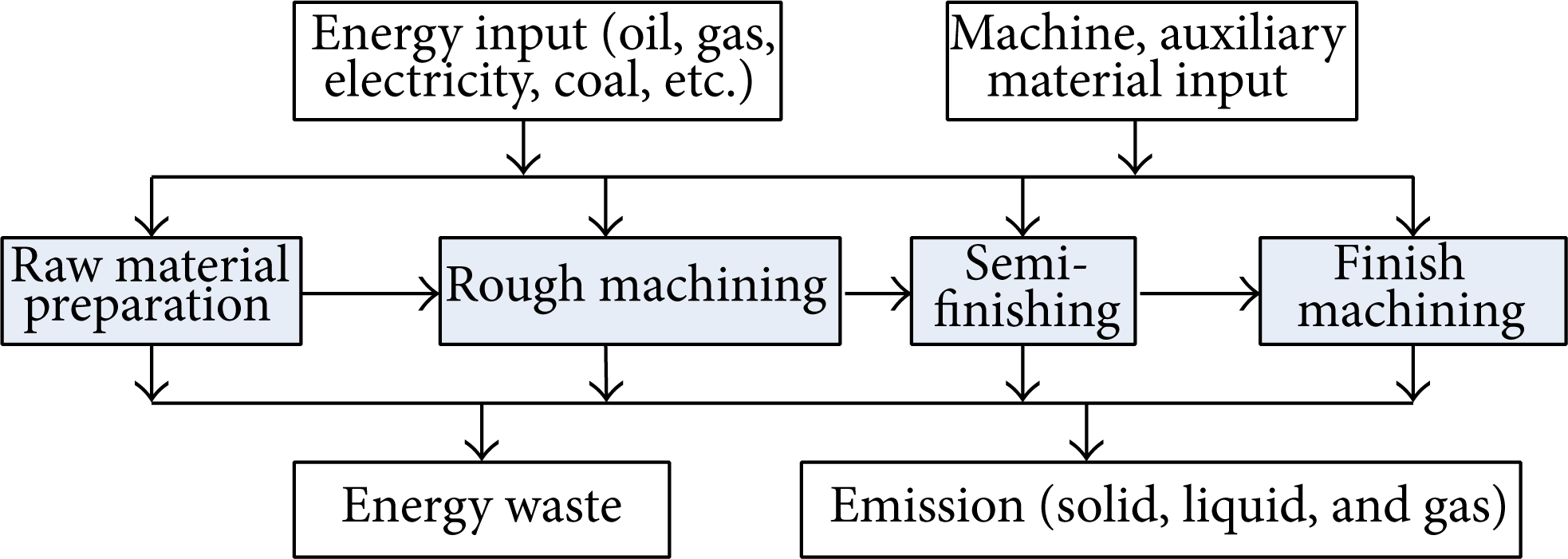
Operation process of the machining system.
Machining system is a facility group, in which the machines are together with each other in the space. A system can independently complete one or one kind manufacturing task. It is obviously that multiple tasks may be allocated to one system, so the tasks must be assigned to the available machines according to some rules, such as priority and deadline. Through the task assignment, the objectives of shortest total production time, lowest production cost, or least energy consumption could be achieved.
Machines are the executors of machining task by implementing the production process. Usually, a machine is structured with mechanical transmission system, motor conversion system, hydraulic system and electric device system, and so forth. Each subsystem requires energy input and the energy use is affected by the process parameters and material pattern, so the energy consumption of machine is uncertain and complex.
4. Energy Model of the Machining System
4.1. Definition of CPN
Coloured Petri nets (CPN) is a 6-tuple: CPN = {P, T, C, I, O, D}, where
P is a finite set of places and T is a finite set of transitions,
C is a set of colours associated with places and transitions, detailed as
the set of colours of place p
i
:
the set of colours of transition t
j
: C(t
j
) = {bj,1,…, b
j,vj
},
where a, b is the color element of the place and transition respectively, and u, v is the color amount of the place and transition respectively.
I(p, t) is the weight function from place p to transition t: C(p) × C(t) → N (nonnegative integer),
O(p, t) is the weight function from transition t to place p: C(t) × C(p) → N (nonnegative integer).
I(a i,h , b j,k ) is the weight function from colour a i,h of place p i to colour b j,k of transition t j , and O(a i,h , b j,k ) is the weight function from transition to place,
D is a set of time functions for transition, D: C(T) → R+ (positive real), D(t
j
) = {dj,1,…, d
j,vj
},
4.2. Energy Consumption Feature of the Machining System
Machining equipment consumes electricity primarily, so the energy of machining process can refer to Gutowski and Thiriez [19]. Cutting energy requirements for material removal processes are made up of the material removing energy and the energy use by equipment supporting the processing, as shown by

where P0 depicts idle power, v depicts the rate of material processing, k is the specific energy requirement in cutting operations, and λ t is the material removal time.
In general, the term P0 can be measured [20], while k is determined by the physical properties of the workpiece [21].
In addition, the volume of removed material V = vλ t , where V is in mm3, then (1) can be transformed into

Visually, if the material removing volume is constant, then the material removing energy is fixed, and it is not affected by the process parameters. The process parameters can only affect the supporting energy through the changing of material removal time; that is, different parameters are chosen, and the material removal times are varied, which leads to the change of supporting energy.
As to total energy requirement of process, it should add the setup energy and idle energy to the cutting energy. In which setup energy is evaluated from the power consumed by the machine and time taken for machine, tool, and workpiece setup, idle energy is evaluated from idle power and time while the machine is in an idle condition. To simplify the energy model, setup energy and idle energy are assumed to be linear to time with gradient of idle power. Therefore, the total energy requirement of process can be depicted by

where Etotal(t j,h ) is total energy requirement by process j to machining workpiece h and d j,h is the operation time of process j to machining workpiece h.
Processing transition stands for the production process of the machining system, and its operation time contains material removing time and auxiliary time. Material removing time is the duration that workpiece is treated, and auxiliary time is caused by the auxiliary operations to support the manufacturing, for example, loading and unloading. Material removing time can be calculated with process parameters, and auxiliary time can survey on site in advance. Take lathing process as an example, the material removing time λ t of one cutting can be obtained with

where Davg is the average diameter of the workpiece in mm, l is the cutting length in mm, f is the federate in mm/rev, and V c is cutting speed in m/min.
Operation times of each workpiece from the same batch are almost the same and just fluctuate a little, so the theoretical operation time should be modified by history experience. Therefore, the time stamp of processing transition j is a discrete uniform distribution function with average d tj , and then the time stamp d j,h of colour a j,h in processing transition t j is

where d tj,h is the average operation time of process j to machining workpiece h in second and d ej,h is the collection time of process j to machining workpiece h in second.
4.3. Energy Model of the Machining System Based on CPN
Machining system is a facility group together with each other in the space, and the unit can independently complete one or one kind machining task. Take one machining system as an example, and the system can complete two tasks with four steps of processes, as shown in Figure 2, in which one process is completed by one machine, and one machine can only carry on one process. The machining time of each process obeys to discrete uniform distribution, and the tasks waiting for processing at the same machine are scheduled randomly. Once the processing transition is fired, the token of energy consumption place is changed correspondingly, so the total energy consumption of each process can be calculated.
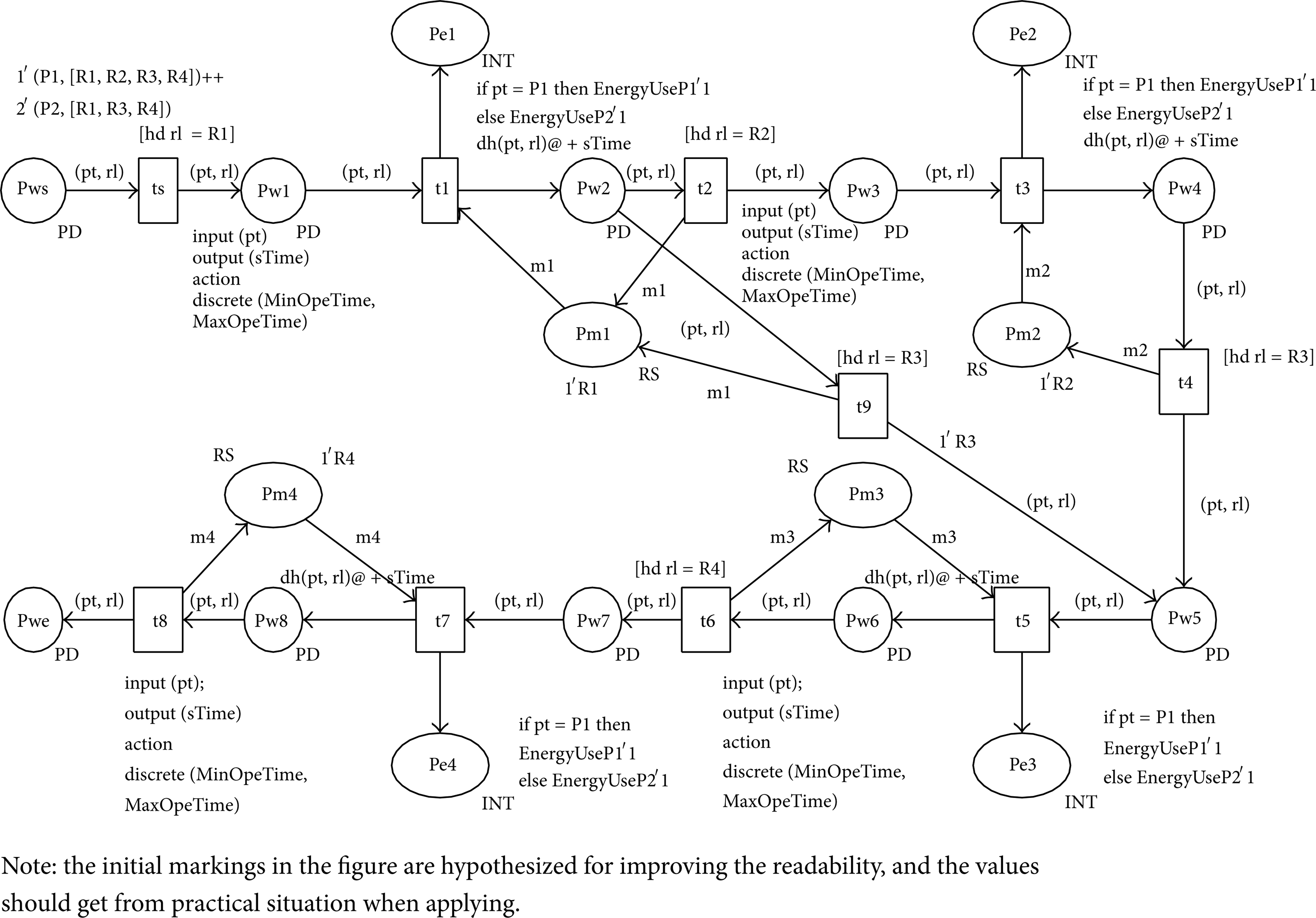
Energy model of the machining system based on CPN.
(1) Places and Transitions of the Machining System Model. As shown in Table 1.
Places and transitions of the machining system model.

(2) Declarations in the Machining System Model
colset INT = int;
colset RS = with R1 ∣ R2 ∣ R3 ∣ R4 timed;
colset RLIST = list RS timed;
colset PT = with P1 ∣ P2 timed;
colset PD = product PT * RLIST timed;
var rl:RLIST;
var pt:PT;
var sTime:INT;
var m1:RS;
var m2:RS;
var m3:RS;
var m4:RS;
fun dh(pt:PT, rl:RLIST) = PD.mult(1′pt, 1′(tl rl)).
(3) Definition of Weight Function
The processing route of each task may be different, so the process need be chosen in the model. We use the weight function of dh(pt, rl) and guard [hd rl=“”] to choose process, where pt is the colour type of task pattern and rl is the colour type of process. In fact, rl is a list of the machining processes, and when the task finished one process, the process will be deleted from the list by weight function dh (pt, rl). Guard constraints [hd rl=“”] of transition ts, t2, t4, t6, and t9 are used to choose the next process. hd rl means choosing the head element of list rl.
The time stamps of processing transitions are discrete uniform distribution. The value of the distribution must be determined according to the practical situation. The values are substituted by several constants in Figure 2, that is, MinOpeTime and MaxOpeTime.
The energy uses of each production process are depicted by constant EnergyUseP1 and EnergyUseP2 in Figure 2. The constants are just some signs with no quantitative meaning, and in practice, the values should be investigated.
5. Case Study
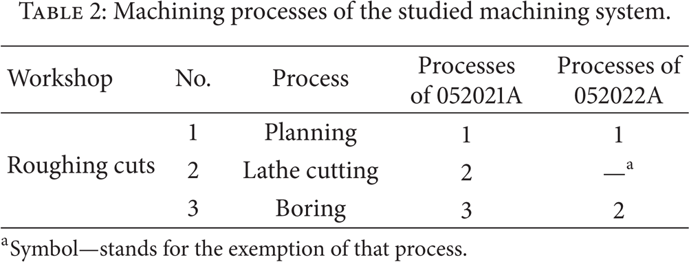
One plant produces the hob box (no. 052021A) and hob arbor carriage (no. 052022A) of hobbing machine, whose raw materials are both cast iron HT300. The two parts are machined through roughing cuts workshop, semifinishing cuts workshop, and finishing cuts workshop, and the processes of roughing cuts are shown in Table 2.
Machining processes of the studied machining system.
In roughing cuts system, the machines are machining equipment which consume electricity primarily, so only electricity consumption is calculated here.
5.1. Data Collection
The feeding proportion of two parts is 1: 2. And the operation time of each process consists of average operation time and collection time, where the average operation time can be calculated by (4) in Section 4.3 and survey on site in advance. And the collection time is determined by experience. The idle power of machine is collected through experiment beforehand. Refer to Kalpakjian and Schmid [21], the specific energy of cast iron is between 1.6 and 5.5 in J/mm3, and we select 3 (J/mm3). The average operation time, material removal volume, and idle power of each machine for the two workpieces are shown in Table 3, where material removal energy is evaluated by the specific energy of workpiece and material removal volume.
Initial data for simulation.
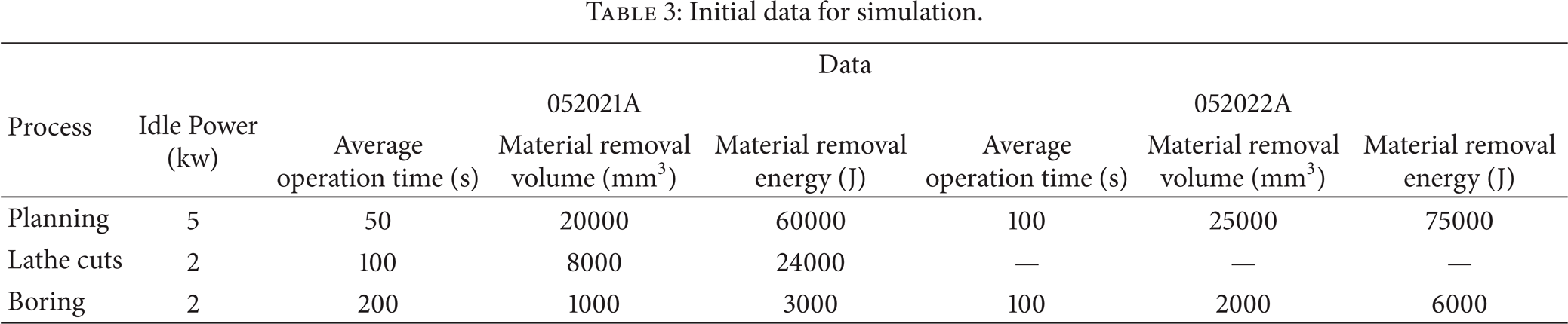
There are 3 planers, 2 lathes, and 1 boring machine. One machine can only process one workpiece at certain time, and one workpiece can only be machined by one machine at certain time, too. All the machines are available at the beginning of the production and equipment failure is not considered in this model.
5.2. Energy Model of the Roughing Cuts System
Energy model of the roughing cuts system based on CPN is set up as shown in Figure 3.

Energy model of the roughing cuts system based on CPN.
The places and transitions are similar to these in Table 1, and the declarations are shown as follows:
colset INT = int timed;
colset E = with e timed;
colset RS = with R1 ∣ R2 ∣ R3 timed;
colset RLIST = list RS timed;
colset PT = with P1 ∣ P2 timed;
colset PD = product PT * RLIST timed;
var rl:RLIST;
var pt:PT;
var sTime:INT;
fun dh (pt:PT, rl:RLIST) = PD.mult(1′pt, 1′(tl rl)).
5.3. Simulation and Analysis
5.3.1. Results
CPN Tools (Version 3.2.2) is used to simulate the CPN energy model. The simulation runs 170 steps and the simulation time is 4086 s.
The average energy consumption of each process to machine a single workpiece can be calculated by the simulation results, as shown in Table 4. With the average energy consumption information, the energy required to produce one workpiece by the roughing cuts system can be obtained, which is an important index for predicting the energy requirements of one facility and a workpiece.
Average energy consumption of each process.

The total energy consumed to complete the tasks is 24905 kJ, then the energy consumption of the machining system per time is 6095 J/s, and the processing velocity is 0.441 item/min, and average processing time of each workpiece is 136.2 s/item.
5.3.2. Discussion
Energy quota is a standard to evaluate the efficiency of the machining system, such as the energy consumption to produce one product or complete one task. Proper energy quota can improve the energy performance of the machining system; however, there are not systematic energy assessing system for machining process currently. Therefore, one important development trend of energy research on the machining system is to assess the energy consumption of producing one part or product and then provide fundamental data for government or industry to establish energy quota rules and promote energy saving policies. The simulation results of the case study can generate the average energy consumption of each processing task, and the energy consumption of parts and products can be obtained also through combining the simulation of all machining systems in the factory. As a result, it proves that the energy model proposed in this paper is practical.
6. Conclusion
The energy consumption process of the machining system is complex, so it is necessary to give some simplified and practical energy analysis methods for the machining system. Firstly, the energy flow of the machining system is analysed. And then one simplified energy calculation method is applied in this paper. The energy use of process is broken down to material removal energy, setup energy, and idle energy, where the material removal energy equals the material cutting specific energy multiplied by the removal volume, and the other energy is evaluated from the idle power of machine and the total operation time for simplification. In this way, we can calculate the energy consumption of manufacturing process with four parameters, that is, idle power of machine, operation time, material pattern, and material removal volume. Finally, the CPN energy model of one case machining system is simulated by CPN tools. And based on the discussion of the simulation results, the energy model proves to be practical.
In fact, there are some limitations of the energy model proposed in this paper. For instance, energy consumption of the machining system is defined to be discrete events in this paper but actually it is a continuous process. In the future, a hybrid energy model combining the discrete manufacturing events and continuous energy consumption process can be studied.
Conflict of Interests
The authors declare that there is no conflict of interests regarding the publication of this paper.
Footnotes
Acknowledgments
The authors gratefully acknowledge the financial support of the National High-Tech R&D Program of China (863 Program) (no. 2014AA041506) and Scientific and Technological Research Projects of Education Department of Jiangxi Province (no. GJJ13003).