
Abstract
Tribological parameters are dependent upon inter alia, inner component properties which may vary with the temperature-time behaviour of the polymer melt used. This temperature-time behaviour can be influenced by dynamic mould temperature control. The present paper presents a new dynamic tempering concept, which enables a targeted temperature-time control via shifting a mould cavity within two different tempered mould areas at a defined point in time. By influencing the temperature-time development by means of a mould temperature and isothermal holding time variation, micro tensile bars with different inner component properties are produced. To show the influence of inner component properties on tribological parameters, pin-on-disc wear tests are performed. Furthermore, tribological tests with different surface topographies are performed to show the influence of topographical properties on tribological parameters. Results indicate that the tribological properties of microparts are mainly influenced by the nature of the skin near layers, which can be influenced by the application of different mould temperatures. Variations in the isothermal holding time show no significant impact on the material examined. A more distinct roughness of the disc surface topography not only shows higher values for the measured tribological parameters but also different wear behaviour in general.
1. Introduction
Microtechnology has increasingly gained importance in recent years [1]. To a large extent, the demand for microparts is determined by the continuously growing micro electro-mechanical systems (MEMS) industry [2]. Microparts made of plastic are of particular economic interest because of their comparatively low manufacturing costs and have partially found their application in bio- and medical-technology [3, 4].
The production of plastic parts via injection moulding causes high cooling velocities of the polymer melt in the component edges. This influences the development of inner component properties (e.g., morphology, degree of crystallisation, and orientations) which are mainly dependent on the temperature-time progression of the cooling melt as well as the pressure conditions during production. For thermal nucleation, the maximum nucleation velocity exceeds the growth velocity [5]; see Figure 1.

The polymer melt's high cooling velocities, for example in component edges with contact to the cavity wall, result in a fine spherulitic morphology or even a morphology that, optically, appears amorphously due to high nucleation and low growth velocity. In the middle of an injection-moulded component, the comparatively slow cooling velocity of the polymer melt leads to distinct spherulites due to a low nucleation and high growth velocity.
Aside from the visible change of the morphological structure, the amount of the crystalline structures also changes. This amount, known as the degree of crystallisation, is also dependent upon the thermal conditions of the melt cooling. In this regard, the degree of crystallisation decreases with increasing cooling velocity [6–8]. For example, measurements for determining the degree of crystallisation at parts produced of polyoxymethylene reached 75% in the core area and 65% in the skin near layer [9].
Studies on polyamide microparts for determining mechanical parameters were able to show that a distinct morphological structure with a high degree of crystallisation shows a higher tensile strength and lower elongation at break than microparts with low degree of crystallisation and morphology that, optically, appears amorphously [10].
While the influence of inner component properties on mechanical properties has been investigated in different publications [9, 10], there is still a great deficiency in the study of the influence on tribological properties, especially for microcomponents.
Tribology is the study of friction and wear, a concept a development engineer may need to take into account for part design and material selection. In sliding rails or machine elements, such as gears or clutches, tribological properties provide a particular challenge [11, 12].
Tribological behaviour cannot be easily predicted. As friction and wear coefficients are not only dependent on the materials employed, but also on the surface topography and load spectrum, for example, they cannot be regarded as material constants. Consequently, tribological behaviour has to be considered within a tribological system [13–15]. A few important parameters within a tribological system are shown in Figure 2.

A tribological system [11].
Two basic factors of a tribological system are friction and wear [11]. An evident industrial demand for plastic parts independent of their dimension is their performance optimization with respect to friction and wear behaviour. By varying processing conditions while moulding, the inner properties of the part (e.g., morphology, degree of crystallisation, and orientation), especially of the skin near layer, can be significantly affected. Since friction and wear are based on the microcontacts between surfaces, the tribological behaviour is influenced by the locally inner properties of the plastic parts with conventional dimensions [16]. Furthermore, studies on determining the tribological parameters of macroscopic components showed that lower wear parameters were achieved with increasing spherulite size and degree of crystallisation [17]. A transfer to microscopic dimensions has not been examined in detail yet.
One option for reducing the cooling velocity of the polymer melt in the surface area and influencing the component properties of semicrystalline thermoplastic polymers is to increase the mould temperature, for example with dynamic mould temperature control [18]. A theoretical approach to change especially the near-surface material structures is to influence the temperature-time progression through maintaining the mould temperature after the injection in a time-defined fashion.
In this paper a new mould concept is presented that enables dynamic temperature control via shifting the cavity from a highly tempered to a cooled mould section. Furthermore, the temperature- and time-dependent formation of the inner component properties as well as the resulting influence on the tribological behaviour of these components is examined. For this purpose, different mould temperatures and isothermal holding times were selected. In addition, the influences of different topographies of metallic wear partners on the resulting tribological parameters of microcomponents are examined.
2. Materials and Methods
2.1. Dynamic Tempering Concept
To ensure complete mould filling, the injection moulding parameters must be coordinated properly. By increasing the injection speed, higher filling levels can be achieved [19]. A further possibility is to increase the mould temperature above the processed material's melt temperature [20], for example, via a dynamic tempering concept. Currently, several methods for dynamic temperature control are employed in industry. These methods differ in how the temperature control is executed:
liquid media (oil, water, CO2),
electrical resistance heating elements,
induction heaters,
infrared thermal emitters.
To examine the influence of different isothermal holding times on inner component properties, apart from high mould temperatures, particularly high cooling gradients at a specific point in time are necessary. Yao et al. [21] already showed that moving a component within two different tempered areas can obtain high cooling gradients and reduce the cycle time significantly. For this purpose, a new approach to rapid and dynamic temperature control was previously developed by the Institute of Polymer Technology (LKT) of Friedrich-Alexander-University Erlangen-Nuernberg, Linde AG and quattro-form GmbH in previous years. This concept, which gets introduced in this paper, enables the production of micro tensile bars and microgears at mould temperatures up to 180°C at a defined isothermal holding time with high cooling gradients by means of a two-part mould design, Figure 3. The upper mould area (marked in red) is heated with water to a constant temperature. The lower mould area (marked in blue) is cooled by liquid CO2. The cavity is placed in an ejector half-sided insert and can be translated vertically within the two different tempered mould areas by a hydraulic piston. The nozzle sided cavity is also placed in a mould insert, which moves synchronously with the mould insert containing the ejector. By moving the cavity from the tempered area to the cooled area, the sprue becomes separated. For optimum heat transfer, the different movable inserts are made of highly heat-conductive steel. This should enable a maximum cooling gradient. Furthermore, the mould temperature of the ejector half cavity can be measured during the entire process.
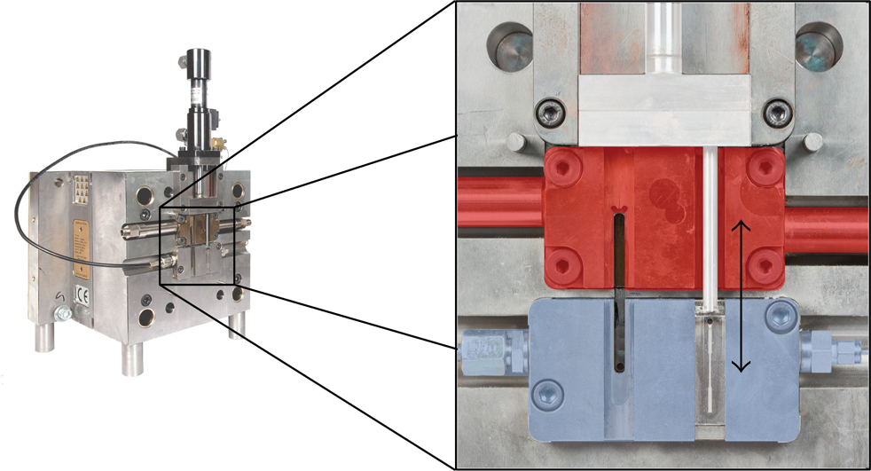
Ejector half of the present mould design.
2.2. Material, Specimen, and Processing
To examine the temperature-dependent correlations between the morphological and tribological properties of the microcomponents, micro tensile bars were injection-moulded with an Arburg 370U 700-30/30 injection-moulding machine with a screw diameter of 15 mm. The material used was polyoxymethylene (POM Hostaform C9021, Ticona). The 1: 16 scaling (total length 28 mm, thickness 0.25 mm) of the tensile bar is derived from the Campus tensile bar according to DIN EN ISO 527 type 1 a, Figure 4. To attain better clamping in the tensile tests, the total length and both shoulder regions were extended. Furthermore, an extension of the striated tensile bar section enables better handling during the tribological studies.
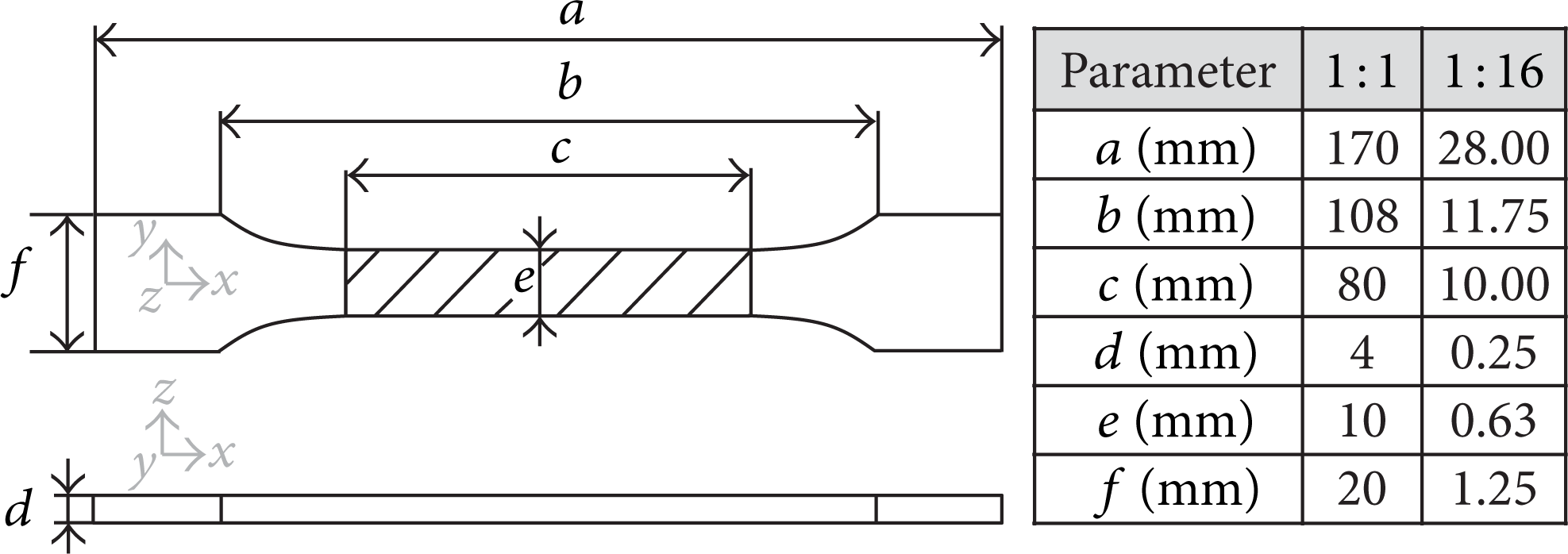
Dimensions of the 1: 16 scaled tensile bar used in comparison to a standardised tensile bar according to DIN EN ISO 527 type 1 a with the striated section used for the tribological test.
The material's crystallisation process during processing was influenced by the application of different mould temperatures close to the crystallisation temperature (T c ) area of about 148°C, Figure 5, where isothermal crystallisation is completed after 66 s. The melt temperature Tmelt was 230°C for all experiments. The variation in mould temperatures and isothermal holding times help to identify the morphological and tribological changes induced by different conditions by crossing the crystallisation temperature. To compare the influence of such high mould temperatures with conventional conditions, a mould temperature of 100°C was additionally used. Table 1 shows the main processing parameters.
Processing parameters for POM tensile bars (1: 16).

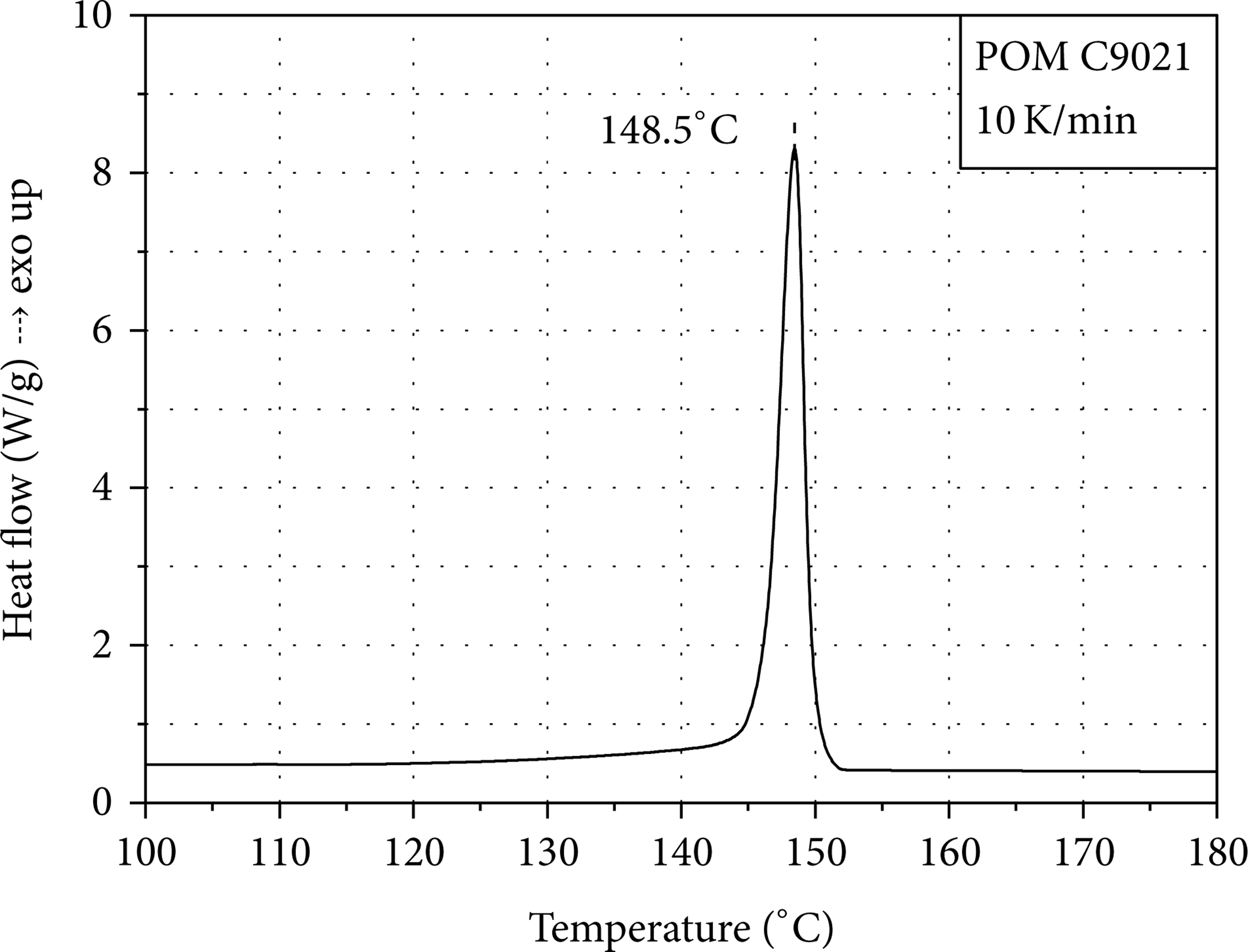
Heat flow at cooling with respect to the temperature measured by DSC.
Figure 6 shows two schematic diagrams of the component temperature progression during a dynamic production cycle. Starting from the melt temperature, the temperature decreases to the mould temperature (shear heating is neglected). The time between the injection starting and the cooling starting consists of the injection time, the holding pressure time, the isothermal holding time, and the moving time of the cavity insert from the highly tempered area into the cooled tempered area. The time to reach the ejection temperature corresponds to the cooling time. Here, an isothermal holding time of 0 s means that the cavity is shifted into the cold mould area 0.8 s after the injection start.

Schematic component temperature profile in the dynamic temperature control process ((a) variation in the mould temperature; (b) variation in the isothermal holding time; t* = tph + t h + t m ).
2.3. Analysis
2.3.1. Determining Mould Temperature Parameters
The temperature measurements are performed at 100°C and 150°C. The mould temperature is measured via an infrared camera PIR uc 180 from InfraTec GmbH at the open mould. The measuring accuracy is ± 1°C up to a temperature of 120°C and ± 2°C above 120°C. The temperature is also measured during the injection moulding process. This is implemented by a K thermocouple (cl. 1), which is located in the ejector half insert close to the cavity. Furthermore, the cooling gradient is measured.
2.3.2. Morphology
The semicrystalline morphology in the cross-section of the micro tensile bars is investigated by polarised light microscopy (Axio Imager. M2 from Zeiss) at under 45° at 10 μm-thin cuts. The thin cuts were taken from the middle of the tensile bar along the direction of injection.
2.3.3. Determining the Degree of Crystallisation
Determining the degree of crystallisation is accomplished by an infrared spectrometer Nicolet 6700FT-IR from Thermo Scientific. The measurements are performed at 5 μm thin cuts in 10 μm steps throughout the cross section. The band ratio of the determined wave numbers is 1238 cm−1 to 1383 cm−1. These wave numbers were determined in preliminary tests and are suitable for a qualitative analysis of the degree of crystallisation.
2.3.4. Pin-on-Disc Wear Testing
The tribological parameters wear coefficient and wear path are conducted with a pin-on-disc test. A schematic setup is shown in Figure 7.

Pin-on-disc test.
The plastic pin (10 mm × 0.25 mm × 0.625 mm) is cut out of the tensile bar (striated section Figure 4) and pressed against a rotating steel disc. The rotational speed of the disc and thus the sliding speed v of the interface to the pin, as well as the applied force and the corresponding pressure p, are the setting parameters (v = 0.5 m/s; p = 4 N/mm2). The ambient temperature T is held at a constant 23°C, and the tribological contact is kept in a technically dry state.
While the disc is rotating, the pin wears and its decreasing length is measured by a displacement transducer. The friction force F R is measured by a load cell, which detects the transverse force exerted onto the pin by the rotating disc and the applied normal force F N . In the tribological tests the wear coefficient and wear path are analysed within the time t r , which is set at 30 minutes, Figure 8.

Wear coefficient and wear throughout running-in and stationary phases (a) and throughout the running-in phase (b) [17].
Based on the results from further examinations [18], the different tribological tests are performed on the same sliding track of the steel disc to reduce the effects of different steel surfaces. Furthermore, the steel discs are cleaned with isopropanol and acetone between each individual measurement to reduce possible material transfer.
To show the influence of different topographies on tribological parameters, two steel discs with different topographies are used for the tribological tests. The Rz-values of the different steel discs are 0.5 ± 0.03 μ m and 1.5 ± 0.04 μm. Rz 1.5 μm is typical for industrially treated steal surfaces and allows for a transfer to industrial applications [17]. 0.5 μm is chosen to get better resolution in the wear tests and for closer investigation of the influence of topographical properties on tribological parameters. The matrix of the tribological investigations is shown in Table 2.
Matrix for tribological investigations.

3. Results and Discussion
3.1. Mould Temperature Parameters
The measurements of the temperature distributions conducted with the infrared thermographic camera show a constant temperature along the entire tensile bar length. Figure 9 shows the measured infrared pictures for a mould temperature of 150°C and an ejection temperature of 10°C.

Temperature distribution along the tensile bar length for a mould temperature T m of 150°C and an ejection temperature T e of 10°C, ejector half.
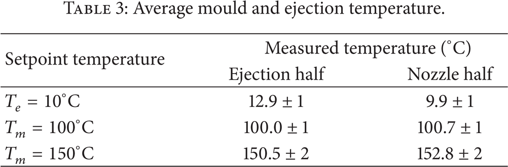
The average mould temperature T m equals 150.5 ± 2°C. In the tensile bar shoulders the measured temperatures are slightly higher than in the middle area, whereby the temperature difference is within the accuracy of the measurement. With 12.9 ± 1°C the ejection temperature is slightly above the setpoint temperature. The temperature distribution throughout the cross section shows a homogenous temperature distribution. Table 3 shows the average mould and ejection temperatures.
Average mould and ejection temperature.
The even temperature distribution can be attributed to the high thermal conductivity of the insert material.
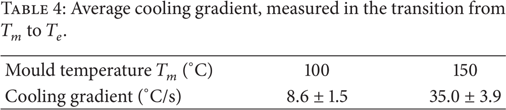
The measured cooling gradients are presented in Table 4. Figure 10 shows the temperature curve of an individual measurement throughout a production cycle at a mould temperature of 150°C. The measurement range for measuring the cooling gradient is marked in the figure.
Average cooling gradient, measured in the transition from T m to T e .

Temperature curve of an individual measurement at a mould temperature of 150°C.
Due to the highest temperature delta, the cooling gradient reaches the highest values at a mould temperature of 150°C. The average value is 35.0°C/s. By reducing the mould temperature, a lower temperature difference influences the cooling gradient to lower values. Therefore, 100°C reaches an average cooling gradient of 8.6°C/s and, consequently, a significantly lower value.
3.2. Morphological Structure
Figure 11 shows the different morphologies with respect to the examined isothermal holding times and mould temperatures throughout the micro tensile bar's cross section. Regarding the different mould temperatures, a reduction in the oriented skin-near layer (blue area) with an increasing mould temperature can be detected.

Morphology of the POM micro tensile bars with respect to mould temperature and isothermal holding time (10 µm-thin cuts, polarized light microscopy).
Orientations are directed agglomerations of molecular chains which can be influenced by viscosity and forces applied to the molecules, for example induced by flow velocity gradients. The reduction in the oriented skin-near layer with the longer reaction time and the lower viscosity of the melt can be explained with higher mould temperatures. From 100°C to 150°C the oriented skin-near layer decreases from about 45 μm to 20 μm. With a further increase in the mould temperature to 170°C, no oriented skin-near layer along the flow direction can be detected. In addition to the reduction in the oriented skin-near layer, the transcrystalline layer also decreases with an increasing mould temperature and shifts towards the component edge. The reduction in the transcrystalline layer can be explained by the increasing mould temperature. Due to a high mould temperature, a higher temperature in the component area of the transcrystalline layer occurs. The high growth velocity and the slow nucleation velocity (cf. Figure 1) result in visible spherulites. As a result of the skin-near- and the transcrystalline layer reduction, the core layer increases with an increasing mould temperature.
With an increasing isothermal holding time, an increasing spherulite size can be detected in the core layer for parts produced at 100°C and 150°C. This can be reduced to the time-dependent development of the morphology. The long dwell time at temperatures with low nucleation velocity and high growth velocity cause greater spherulites.
3.3. Degree of Crystallisation
Figure 12 shows the measured band-ratios and the degrees of crystallisation with respect to the component's cross section for mould temperatures analysed at an isothermal holding time of 20 s.
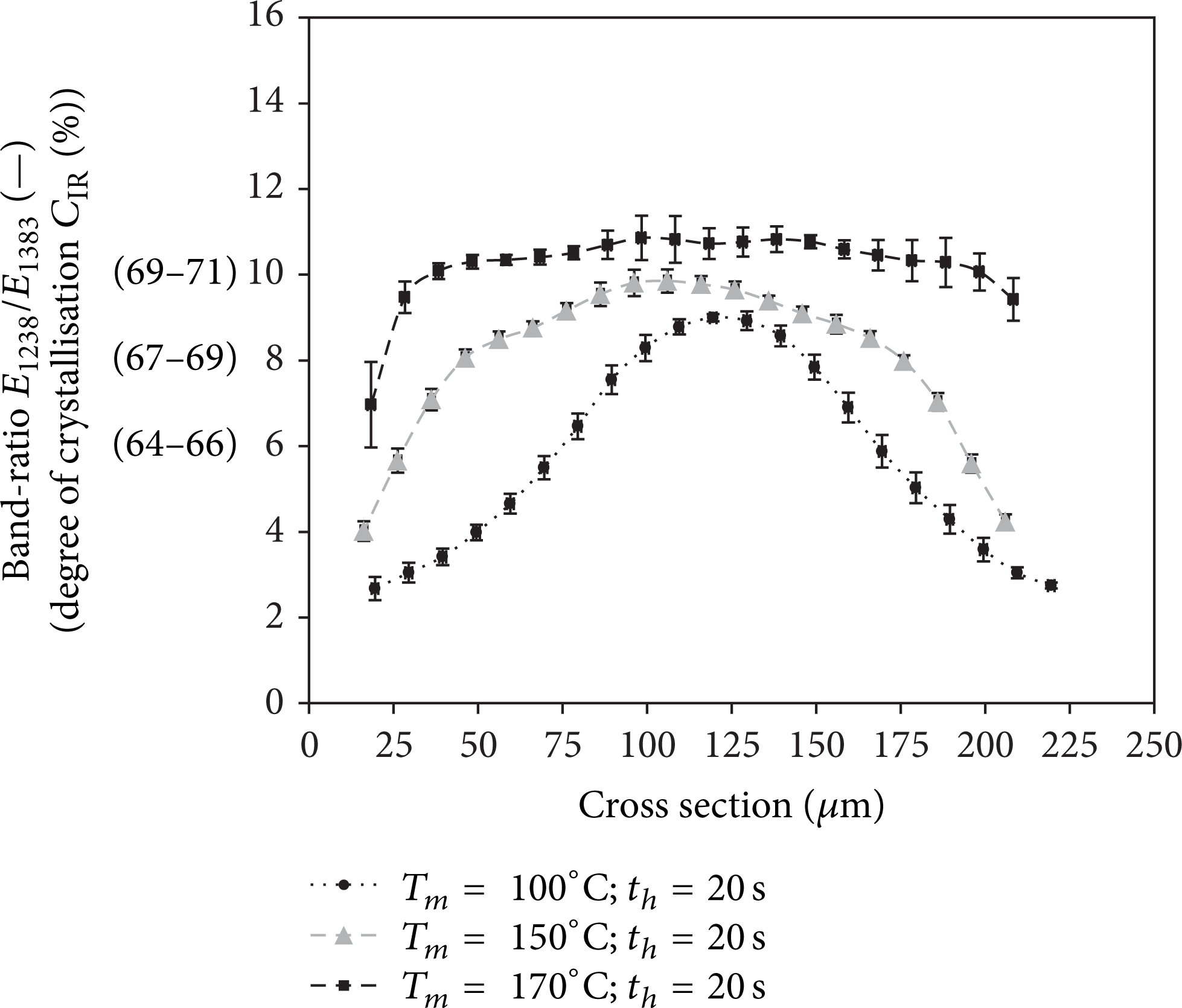
Band-ratio and degree of crystallisation with respect to the cross section for different mould temperatures at an isothermal holding time of 20 s.
For the examined mould temperatures, analyses show a significant increase in the degree of crystallisation from the component edge to the core area. Compared to 100°C and 150°C, the increase for components manufactured at 170°C is less pronounced. Furthermore, an increasing mould temperature results in a considerably broader core area with slightly higher degrees of crystallisation. In addition, the degrees of crystallisation in the edge area increase with an increasing mould temperature.
Compared to the morphologies in Figure 11, the highest degrees of crystallinity occur in the distinct spherulitic structures and in the core area. In the oriented and the semicrystalline area, the degree of crystallisation increases significantly. The reason for the increasing degrees of crystallisation with increasing mould temperature can be reduced to the temperature-dependent crystallisation process. Higher temperatures support the nucleation and the growth process.
The measured degrees of crystallisation for the isothermal holding times examined at mould temperatures of 150°C and 170°C are shown in Figure 13.

Band-ratio and degree of crystallisation with respect to the cross section for different isothermal holding times at mould temperatures of 150°C (a) and 170°C (b).
The measured degrees of crystallisation at 150°C mould temperature and 0 s isothermal holding time reach slightly lower values than 20 s and 70 s, although the differences are within the measuring accuracy. At a mould temperature of 170°C, the measured degrees of crystallisation for an isothermal holding time of 70 s are located slightly below the values of 0 s and 20 s. Again, the differences are within the measuring accuracy. Consequently, the influence of the isothermal holding time is negligible in the present analyses. The minor effects of the isothermal holding time variation are reduced to the material used. POM is a comparatively fast crystallising material. Furthermore, the addition of nucleating agents speeds up the crystallisation process.
3.4. Tribological Behaviour
The results of the tribological tests with a steel disc of Rz = 0.5 μm are summarized in Figure 14. Comparing the tribological results at different mould temperatures with an isothermal holding time of 0 s, no significant differences are measured.

Wear coefficient k r and wear path x r with respect to different mould temperatures and isothermal holding times, Rz = 0.5 μm.
At an isothermal holding time of 20 s, a significant increase in the wear parameters can be measured from 100°C to 150°C. In comparison to 150°C, the wear parameters of parts produced at 170°C are significantly lower, while at 100°C tendentially lower wear parameters are exhibited. At an isothermal holding time of 70 s, no significant difference between 100°C and 150° is evident. With a wear coefficient of 1.3·10−6 mm3/Nm and a wear path of 4.4 μm, the lowest average values are measured at 170°C at an isothermal holding time of 70 s. These tend to be below the measured wear parameters of 100°C and significantly lower than the measured values for 150°C. In general, the tribological parameters at a mould temperature of 170°C reach the lowest wear parameters, while the parameters at a mould temperature of 150°C tend to reach the highest. The low wear parameters at 170°C are attributed to the high degree of crystallisation and the distinct spherulitic structure. Regarding the isothermal holding time of 20 s, in contrary to assumptions in literature, the wear parameters of parts produced at 150°C achieve higher wear parameters than parts produced at 100°C. The inner properties of samples produced at 100°C and 150°C significantly differ in the degree of crystallisation and the thickness of the oriented edge layer. For additional characterisation and clarification, further research and analysis, for example, on α- and γ-crystallisation, on the lamellar structure as well as the pressure-dependent influences in processing are needed.
There are no significant differences comparing the wear parameters of parts produced at various isothermal holding times. This can be reduced to minor differences in the inner component properties with various isothermal holding times.
To investigate the influence of topographical properties on tribological parameters, tests using sliding partners with different roughness were conducted. The results for measurements at Rz 1.5 μm are shown in Figure 15. Comparing the tribological results for different mould temperatures with an isothermal holding time of 0 s significant differences are yielded.
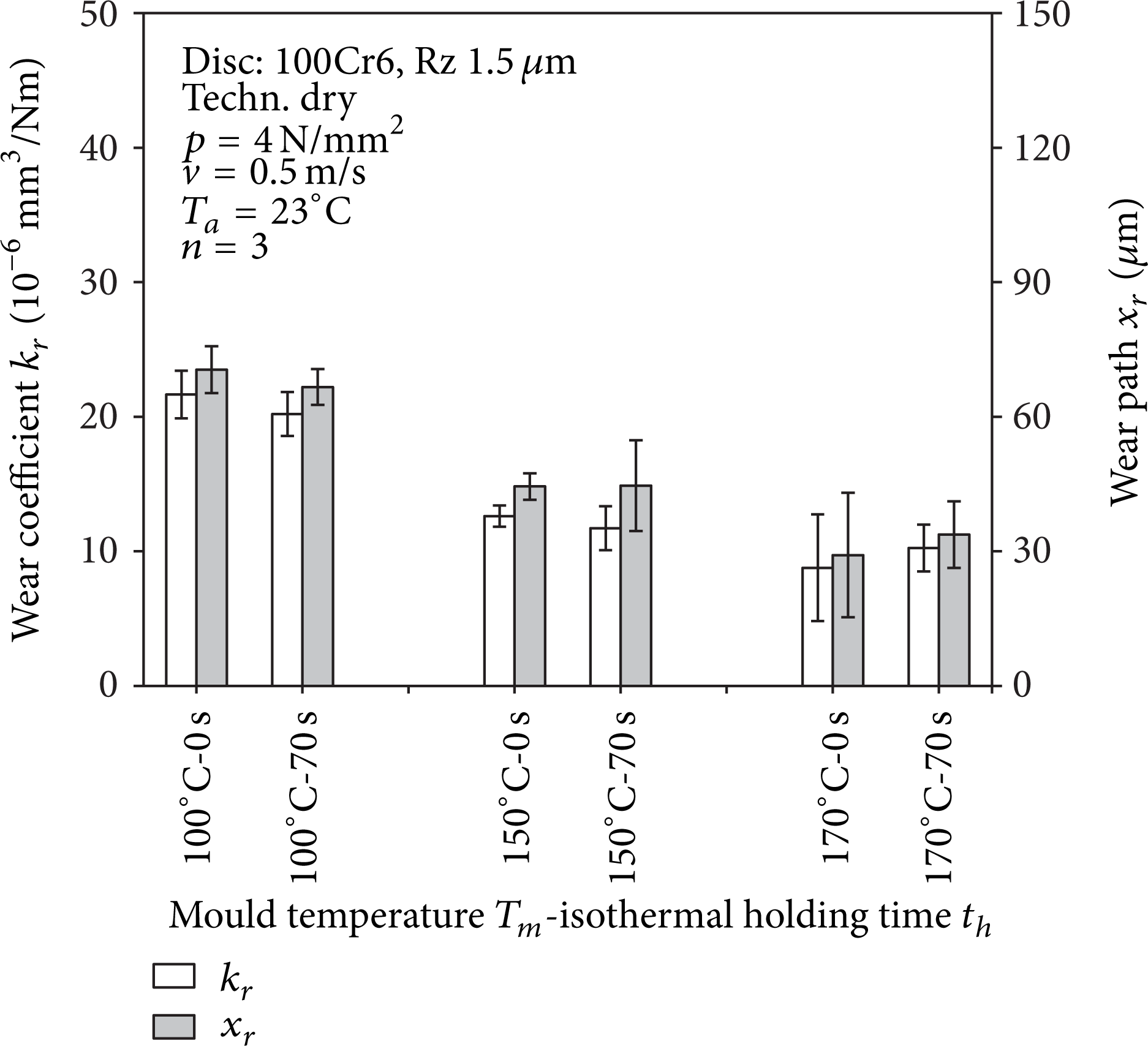
Wear coefficient k r and wear path x r with respect to different mould temperatures and isothermal holding times, Rz = 1.5 μm.
The specimen produced at a mould temperature of 100°C reaches the highest wear coefficient and wear path. The results of the specimen produced at a mould temperature of 150°C and 170°C show significantly lower values for k r and x r . The tribological tests at 0 s isothermal holding time with parts produced at a mould temperature of 170°C tended to reach the lowest wear parameters. This also applies to samples produced at an isothermal holding time of 70 s. The wear parameters for 100°C reach the highest values, whereas the values for 150°C and 170°C are significantly lower. The tribological results are consistent with other published results. With an increasing mould temperature, the spherulite size and the degree of crystallisation increase, which results in less wear. When comparing the different isothermal holding times, the measurement results show no significant differences, which can be explained by the similar morphologies and degrees of crystallisation. Compared to the measurements at Rz 0.5 μm, the wear parameters measured at Rz 1.5 μm reach significant higher values. Due to the coarser steel topography, an increased material removal occurs. Furthermore, with tests at Rz 0.5 μm, an increase in the wear parameters from 100°C to 150°C tended to arise, while at 1.5 μm a significant reduction was measured. Here, it is assumed that different wear properties occur with different steel surfaces. Further studies are necessary in order to confirm this assumption.
4. Conclusion
This paper presents a new dynamic tempering concept, which enables a dynamic temperature control for the production of microcomponents with targeted influencing the time- and temperature-dependent formation of the inner component properties via a shifting mechanism. The influence of a variation in the isothermal holding time and mould temperature on the inner component properties were investigated by analysing the morphology and by determining the degree of crystallisation. Furthermore, the effects on the wear properties were investigated using a pin-on-disc test. The results show that particularly the mould temperature, and less so the isothermal holding time, influences the resulting morphology. An increasing mould temperature results in a reduction in the oriented skin-near layer and crystalline layer thickness as well as the associated gradient of the degree of crystallisation from the edge to the core.
A variation in the isothermal holding time only shows influence upon reaching the crystallisation temperature range in the form of a growing spherulite size in the core layer with an increasing holding time. Regarding the isothermal holding time, there is no measurable influence on the degree of crystallisation. The morphological changes are limited to the dependence of the inner component properties from the temperature-time progression of the polymer melt.
The pin-on-disc tests for determining the tribological parameters show that samples produced at a mould temperature above the crystallisation temperature range tended to reach the lowest wear characteristics. Thus, skin-near layers with high degrees of crystallisation and spherulitic structures show the lowest wear properties. Samples produced with different isothermal holding time do not show significant differences in the measured wear parameters. Furthermore, pin-on-disc tests with different steel roughness of the disc show the dependence of the wear parameters on the topography. With an increasing roughness value of the disc, the wear of the pin increases due to the higher material removal. In addition, wear characteristics for parts produced with a mould temperature in the area of the crystallisation temperature range seem to be influenced by the dependence of the steel's roughness.
With the practical implementation of the tool concept, the basis for comprehensive investigations has been created. In terms of process control, the interaction of the crystallisation behaviour, for example, with different isothermal holding times as well as the inclusion of pressure as an additional parameter in the structure formation, is of scientific interest. In addition, the knowledge gained can be applied to practical applications, such as microgear tests.
Conflict of Interests
The authors declare that there is no conflict of interests regarding the publication of this paper.
Footnotes
Acknowledgments
The authors would like to thank the Deutsche Forschungsgemeinschaft (DFG) for funding the work in the project DR 421/9-1. Furthermore, the authors acknowledge the support from the Deutsche Forschungsgemeinschaft and Friedrich-Alexander-Universität Erlangen-Nürnberg within the funding programme Open Access Publishing. The authors also extend their gratitude to their industrial partners, quattro-form GmbH, for supporting the mould design, Linde AG and gwk Gesellschaft Wärme Kältetechnik mbH for providing the dynamic CO2-tempering equipment, and Celanese Corporation for providing the material.