
Abstract
This paper presents a novel decentralized integral nested sliding mode control approach for a time varying constrained modular and reconfigurable robot (MRR) and addresses the problem of joint trajectory tracking control of the MRR with strongly coupled model uncertainty. First, the dynamic model of the time varying constrained MRR is described as a synthesis of interconnected subsystems. Second, a decentralized control scheme is proposed based on only local dynamic information of each module. An integral nested sliding surface is implemented to reduce the chattering effect of the controller. Model uncertainties, including the unmodeled subsystem dynamics, the friction modeling error, and the interconnected dynamic coupling, are compensated by a variable gain supertwisting algorithm (VGSTA) based controller. The stability of the close-loop system is proved using the Lyapunov theory. Finally, simulations are performed for a time varying constrained 2-DOF MRR to study the effectiveness of the proposed method.
1. Introduction
Modular and reconfigurable robot consists of robot modules which incorporate power electronics, computing systems, sensors, and actuators. These modules can be serially connected with standard electromechanical interfaces and assembled to desirable configuration for satisfying the requirements of various tasks under different external environments and constraints. An MRR needs an appropriate control system to provide accuracy and stability after reconfigurations.
A number of researches have been made toward the dynamics and control method of MRR. A neurofuzzy hierarchical control architecture is proposed for an MRR which uses learning control to compensate unmodeled system dynamics due to reconfiguration [1]. The adaptive control parameters are updated using a skill module that is a part of the higher level of the control system hierarchy. A dynamic control of robots using a virtual decomposition-based control approach is presented in [2]; following this work, they propose a precision control method for MRR with embedded FPGA [3]. Based on a calculating torque control method, [4] proposes a neurofuzzy compensator to reduce the modeled and unmodeled uncertainty of the modular manipulators. However, these methods are concentrated on the centralized control. Indeed, due to high computation costs, robustness, and complexities, a centralized controller designed on the basis of an entire system may hardly be applicable for controlling an MRR.
Decentralized control is a particularly promising concept in implementing an MRR system. The decentralized control systems often arise from various complex situations where there exist physical limitations on information exchange among several subsystems for which there is insufficient capability of having a single central controller. Furthermore, based on only local dynamic information of the modules, the decentralized control architecture can not only provide the flexibility, which is applicable to all the configurations, but also reduce the computation time that is critical for real-time application to an MRR system. Therefore, both practically and theoretically, it is meaningful to devise an ideal decentralized control architecture for the MRR. A decentralized reinforcement learning robust optimal tracking control theory for time varying constrained MRR based on action-critic-identifier and state-action value function is presented to address the problem of the continuous time nonlinear optimal control policy for strongly coupled uncertainty robotic system [5]. A decentralized active disturbance rejection control method for reconfigurable modular robot is proposed with a high-precision extended state observer to estimate the dynamic model nonlinear terms and the interconnection terms of the subsystems [6]. A decentralized robust control algorithm based on Lyapunov stability analysis and backstepping technique is given for MRR with harmonic drive transmission [7]. A modular control method is proposed based on joint torque sensing technique; with this method, an MRR can be stabilized joint by joint [8]. A calculating torque based robust fuzzy neural network controller is proposed in [9], which is used to solve the problem of model uncertainty in the process of model generating. In [10], a design methodology of interval type-2 fuzzy controller is derived for MRR manipulators with uncertain dynamic parameters. An observer based decentralized adaptive fuzzy controller for reconfigurable manipulator is proposed in [11]. By designing the state observer, the adaptive fuzzy systems which are used to model the unknown dynamics of subsystem and interconnected coupling term can be constructed by using the state estimations.
Some researchers have studied the control method for an MRR that combined the sliding mode control method with the decentralized control scheme. In [12, 13], a stable decentralized adaptive fuzzy sliding mode control method is proposed for modular manipulators to satisfy the concept of modular software. In these researches, the fuzzy logic system is used to approximate the unknown dynamics of the subsystem, and a sliding mode controller with an adaptive scheme is designed to compensate both interconnected coupling term and fuzzy approximation error. However, the main drawback for these control strategies is the so-called “chattering effect,” which is introduced by the one-order sliding surface which is designed directly by using a Lyapunov function and may affect the control precision of the MRR system. Therefore, an excellent control approach for an MRR should be able to compensate the model uncertainty accurately and reduce the chattering effect of the controller.
In this paper, a novel decentralized integral nested sliding mode control approach is proposed to address the problem of joint trajectory tracking control of a time varying constrained MRR with strongly coupled model uncertainty. The dynamic model of the time varying constrained MRR is described as a synthesis of interconnected subsystems. With the decentralized control scheme, only the local dynamic information of each module is required in the controller of the module, so that the modules can be added or removed without the need to readjust the control parameters of the other modules. According to the concepts of integral sliding mode (ISM) [14–17] and nested sliding mode (NSM) [18, 19], an integral nested sliding surface, which is designed by employing a pseudosliding surface block, is implemented to reduce the chattering effect of the controller. A sigmoidal function, which is used to design the sliding surface, is able to introduce robustness in each block, and the integral part will reduce the sliding surface gains. Model uncertainties, including unmodeled subsystem dynamics, friction modeling error, and the interconnected dynamic coupling, are compensated by a VGSTA based controller [20, 21], which can adjust the control gains according to the actual bound of the uncertainty. The Lyapunov theory is used to prove the stability of the close-loop system. Finally, simulations are performed for a time varying constrained 2-DOF MRR to illustrate the effectiveness of the proposed method.
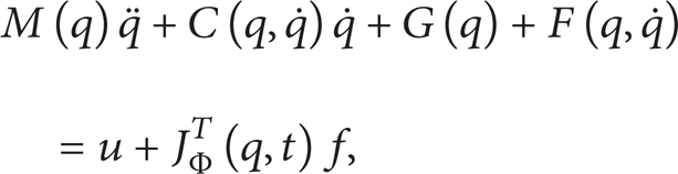
2. Dynamic Model Formulation
Define the time varying external constraint for the end of MRR as follows:

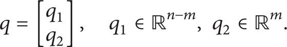
where
where
Define
Substituting (3) into (1), one can obtain that

where
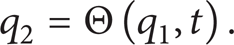
Therefore, (3) can be described with independent joint position q1, shown as

The derivation of (6) is given as follows:

where

Therefore, the second-order derivative of q can be represented as follows:

Substituting (7) and (9) into (2), one can obtain that

Define

so that θ can be rewritten as follows:
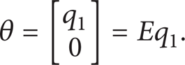
Then, (2) can be decomposed into the following form:

In (13),
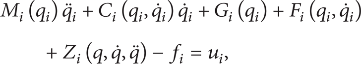
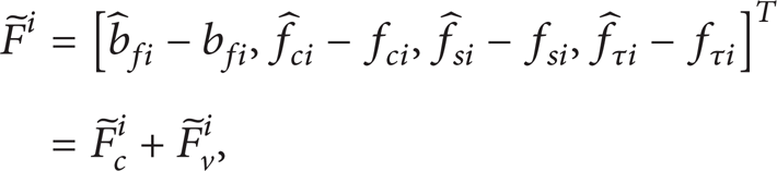
where

It is noted that the joint friction

where f
ci
denotes the Coulomb friction related parameter; f
si
denotes the static friction related parameter; fτi is a position dependency of friction and other friction modeling errors,

and

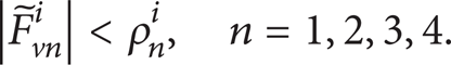
where ρ
fi
is a known constant bound for any position and velocity q
i
and
Therefore, we can obtain the acceleration of the ith joint

where
Define

where x i is the state vector of subsystem S i and y i is the output of subsystem S i . The architecture of the time varying constrained MRR system is shown as Figure 1.

The architecture of the time varying constrained reconfigurable modular robot system.
3. Decentralized Integral Nested Sliding Mode Control
In this section, a decentralized integral nested sliding mode control approach is proposed based on VGSTA, and the stability of the close-loop system is proofed by the Lyapunov theory.
Assumption 1. Desired trajectory yir1(t) is bounded.
Assumption 2. The interconnected dynamic coupling term

where gi0 is a positive constant and g ij is a smooth Lipschitz function.
Define the tracking position error as
Then, we can obtain the derivative of

Define the pseudosliding surface si1 for the first block as

and the derivative of si1 can be given as follows:

In (25) and (26), zi1 is an integral variable which will be defined later. It is noted that, in order to substitute the designed control law into the sliding surface, it is of importance to introduce the second block of sliding surface, which is defined as follows:
where zi2 is an integral variable to be determined, and ei2, which is used to design the second block of sliding surface, can be defined as
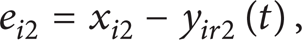
where yir2(t) is defined as

In (29), yir2,0(t) is the nominal part of the control design, and yir2,1(t) is used to design the control law for the purpose of compensating the unmodeled subsystem dynamics.
Substituting (28) into (27), one can obtain that

Combining (26) with (30), the derivative of the pseudosliding surface si1 can be rewritten as

Choose

Then, combining (27) and (31) with (32), the derivative of si1 and zi1 can be represented as

With the initial condition zi1(0) = − ei1(0), define yir2,0(t) and yir2,1(t) as
where k1, σ1, and ∊1 are positive constants to be determined. sigm(·) is a sigmoid function which can be defined as follows:

Figure 2 shows the approximation for various values of ∊1, which defines the slope of the sigmoid function for every si1.

Sigmoid function for various values of the slope σ1.
Then, we can obtain the derivative of si2 as

According to (34), one can obtain that

Substituting (21) into (36), we can rewrite

where

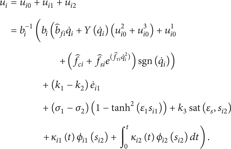
where k2 and σ2 are positive constants to be determined. Note that the integral variable zi2, which is designed with a sigmoid function, is applicable for the chattering alleviation and attenuation of the sliding mode system. Then, for the purpose of compensating the different terms of the derivative of the sliding surface, we can design the control law in the form of u i = ui0 + ui1 + ui2. So (38) can be rewritten as
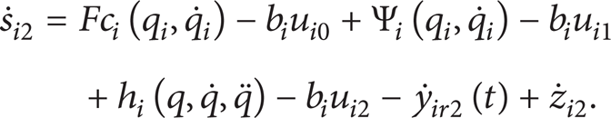
First, design the control law ui0 to compensate the effect of joint friction
where

In order to incorporate variable parametric model uncertainty compensation, we can design
where
In (42),

where
Second, design the control law ui1 to compensate the terms of

where ∊ s and k3 are positive constants to be determined. sat (·) is a saturation function which is defined as follows:

Third, based on the VGSTA theory, design the control law ui2 to compensate the interconnected dynamic coupling term

where gi1(q i , t) and gi2(q i , t) are bounded by

where ςi1|q i , t| > 0 and ςi2|q i , t| > 0 are known continuous functions. φ1(si2) and φ2(si2) are defined as

where κi3(t) is a positive gain to be determined. Substituting (48) into (40), one can obtain that

Design the control law ui2 to compensate the interconnected dynamic coupling term, shown as follows:

where the variable gains κi1(t) and κi2(t) are chosen as

where ϕ, ρ v , and ∊2 are positive constants to be determined. Note that, for the control law ui2, if κi1(t) and κi2(t) are constants and κi3(t) = 0, then it is a standard supertwisting control law. If κi3(t) > 0 and κi1(t) and κi2(t) are designed in the form of (53); then, the variable gains κi1(t) and κi2(t) make it possible to render the sliding surface insensitive to perturbations growing with bounds given by known functions, and the linear growth disturbance of the system can be reduced.
Therefore, combining (41) and (46) with (52), the decentralized integral nested sliding mode control law u i for the ith joint can be defined as follows:
Theorem 3. Given a time varying constrained n-DOF MRR, with the dynamic model as formulated in (14) and the model uncertainties that existed in (20), the close-loop system is stable under the decentralized integral nested sliding mode control law defined by (54).
Proof. The proof of Theorem 3 will be done by using two Lyapunov function candidates for the different block of sliding surface.
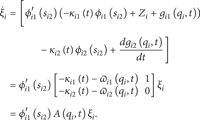
First, we can reformulate the derivative of second block of sliding surface (51) as follows:

where

The Lyapunov function candidate of the second block can be defined as follows:
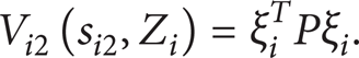
In (57), ξ i T and P in Vi2(si2, Z i ) are defined as


Note that the function Vi2(si2, Z
i
) is positive definite, continuous, and differentiable everywhere. Rewriting the inequation of (49) yields that
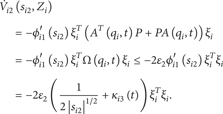
So the derivative of Vi2(si2, Z i ) can be given as

where Ω(q i , t) is given as follows:

where Ω1, Ω2, and Ω3 are designed as

Choosing P in (59) and the gains in (53), we can obtain that

It is obvious that (64) is positive definite. So we can obtain that
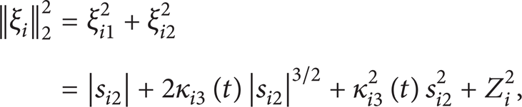
Since

where
where

From (65) to (68), we can get the following equation:

where χ1 and χ2 are positive definite, shown as

The solution of the differential equation
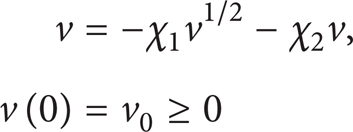
is given by
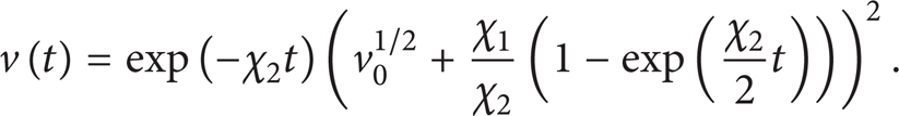
On the basis of the Comparison Lemma [24, Lemma 2.5, p. 85], one can obtain that V i |t| ≤ v|t| when V i |0| ≤ v0. It follows that the equilibrium point |si2, Z i | = 0 is reached in finite time and the reaching time can be estimated by

Second, proceeding in similar way for the first block, we can design the Lyapunov function candidate as follows:

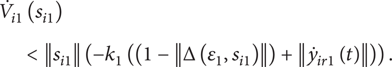
The derivative of Vi1(si1) can be obtained as

Design the following equation:

where Δ(∊1, si1) can be shown as the difference between the signum and sigmoid functions. Then, we can obtain the following equation by combining (75) with (76), shown as
It is evident that Δ(∊1, si1) is bounded while ∊1 is given. There is a positive ϑ (0 < ϑ < 1) with the following equation:
Therefore, we can get the conclusion that
and si1 converges to a region
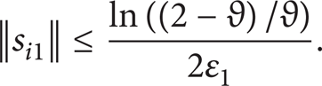
This concludes the proof of the theorem.
4. Simulations
4.1. Dynamic Model
In order to confirm that the proposed control method can be applied in different configurations, in this paper, two different configurations of the time varying constrained 2-DOF MRR, which are shown in Figures 3 and 4, are used to conduct simulations.

Configuration A for time varying constrained MRR.

Configuration B for time varying constrained MRR.
For the sake of the facilitation of the analysis of the configurations shown in Figures 3 and 4, we can transform them into a form of analytic charts, which are shown in Figures 5 and 6, where L1, L2, and L4 are the length of the links. L3 is the distance between the time varying constraint and the base module.

The analytic chart of configuration A.

The analytic chart of configuration B.
The time varying constraint can be defined as a kind of column with the length L5 = 0.5 m and the mass m c = 4 kg, which rotates with a certain degree of freedom. The constraint equations and the end-effector constrained force of configuration A and configuration B are shown as follows:

where g is the acceleration of gravity and α|t| is the angle between the time varying constraint and the x-axis, which can be defined as follows:

The desired positions of configurations A and B are given as follows.
Configuration A:
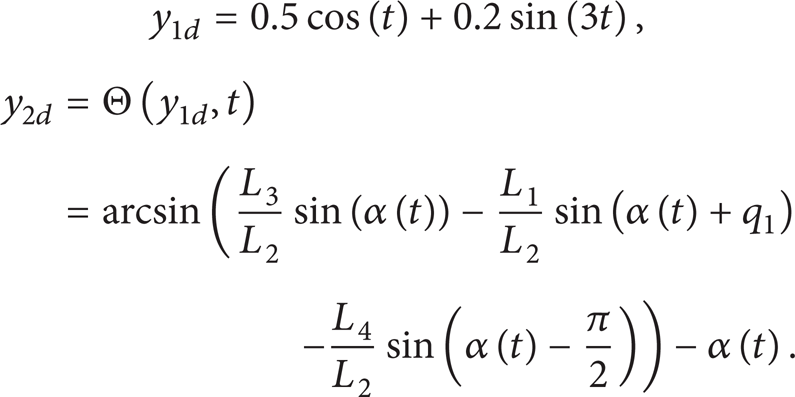
Configuration B:

Note that, due to the limitation of the external time varying constraint, the position variety of joint 1 of configuration B is zero.
The initial positions of the joints are defined as q1|0| = 0 and q2|0| = − 2 for both configurations A and B. The dynamics of configurations A and B are designed as follows:

The parameters of the friction model are given as follows:
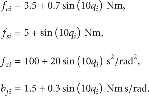
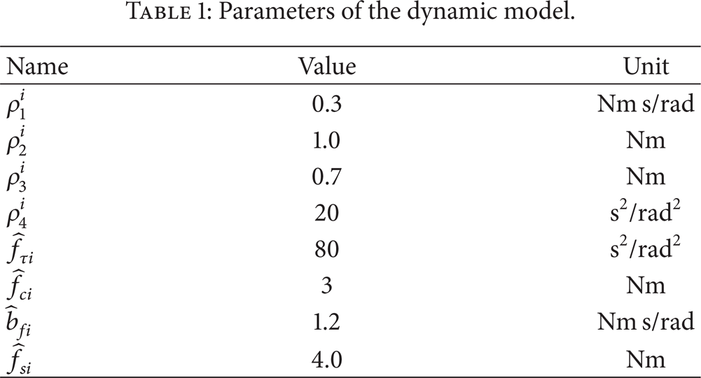
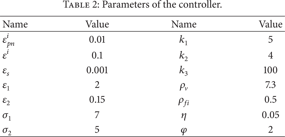
The parameters of the dynamic model and the controller are represented in Tables 1 and 2.
Parameters of the dynamic model.
Parameters of the controller.
4.2. Simulation Results
To verify the effectiveness and precision of the proposed control method, in this paper, the simulations are conducted with two different controllers, respectively, that include the standard supertwisting algorithm (STA) based one-order sliding mode controller (SMC) and the VGSTA based integral nested sliding mode controller (INSMC). The simulation results are shown in Figures 7 to 22.

Joint 1 position tracking curve of configuration A under STA based SMC.
Figures 7, 8, 9, 10, 11, and 12 show the joint position tracking curves and the position tracking error curves of two different configurations under the STA based SMC. From these figures we can conclude that the chattering effects in the initial period are obvious under the STA based SMC. Besides, the standard STA based control method can ensure the convergence of the position error; however, because the control gains cannot be adjusted according to the actual bound of the uncertainty, the periodic position error is relatively obvious under this control.
Joint 2 position tracking curve of configuration A under STA based SMC.

Joint 1 position error curve of configuration A under STA based SMC.

Joint 2 position error curve of configuration A under STA based SMC.

Joint 2 position tracking curve of configuration B under STA based SMC.
Joint 2 position error curve of configuration B under STA based SMC.
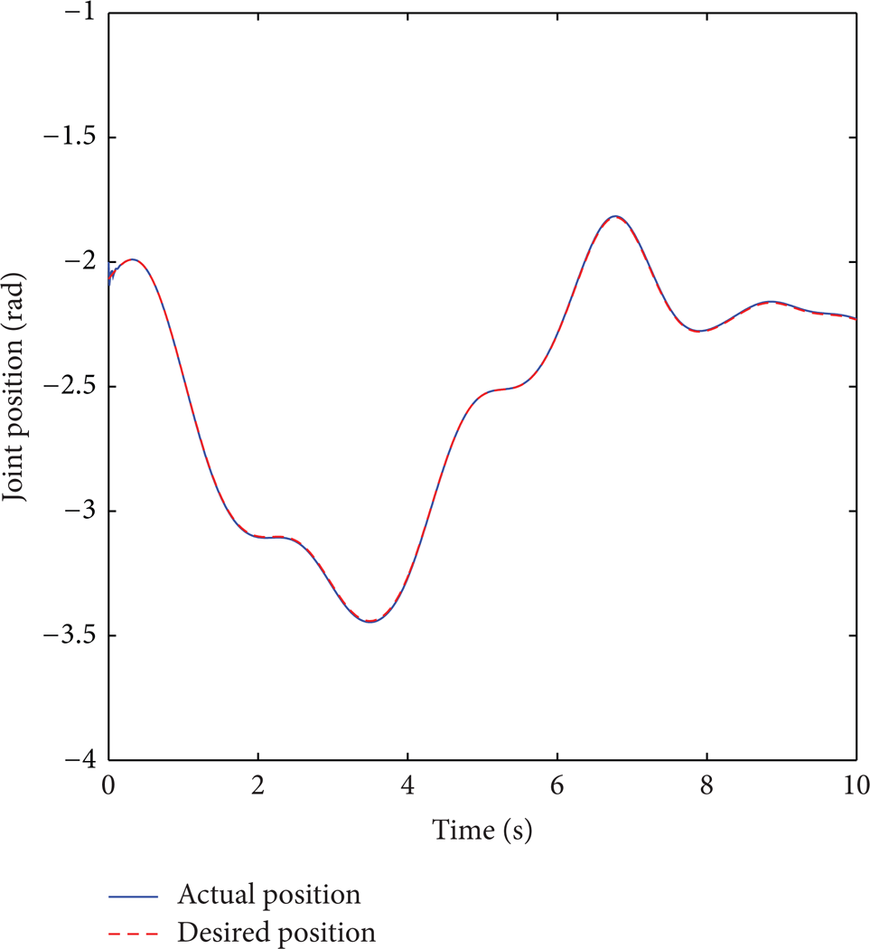
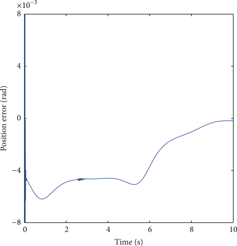
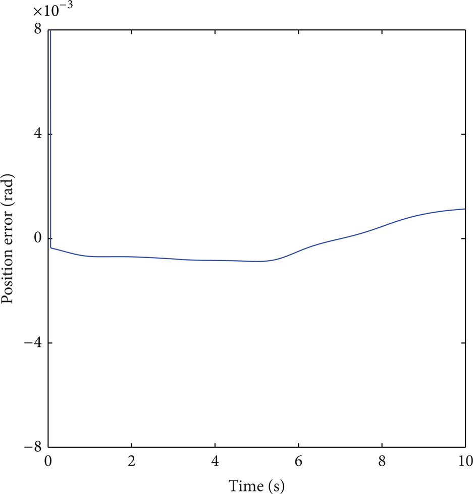
Figures 13, 14, 15, 16, 17, and 18 show the joint position tracking curves and the position tracking error curves of the two different configurations under VGSTA based INSMC. As the simulation results show in these figures, we can conclude that when the VGSTA based INSMC is used, the tracking performance of the joint positions is improved obviously because the model uncertainties have been compensated accurately. The chattering effect can be reduced with the proposed integral nested sliding surface and the sliding manifold can be reached in finite time; after that, the robot system can keep in sliding manifold.
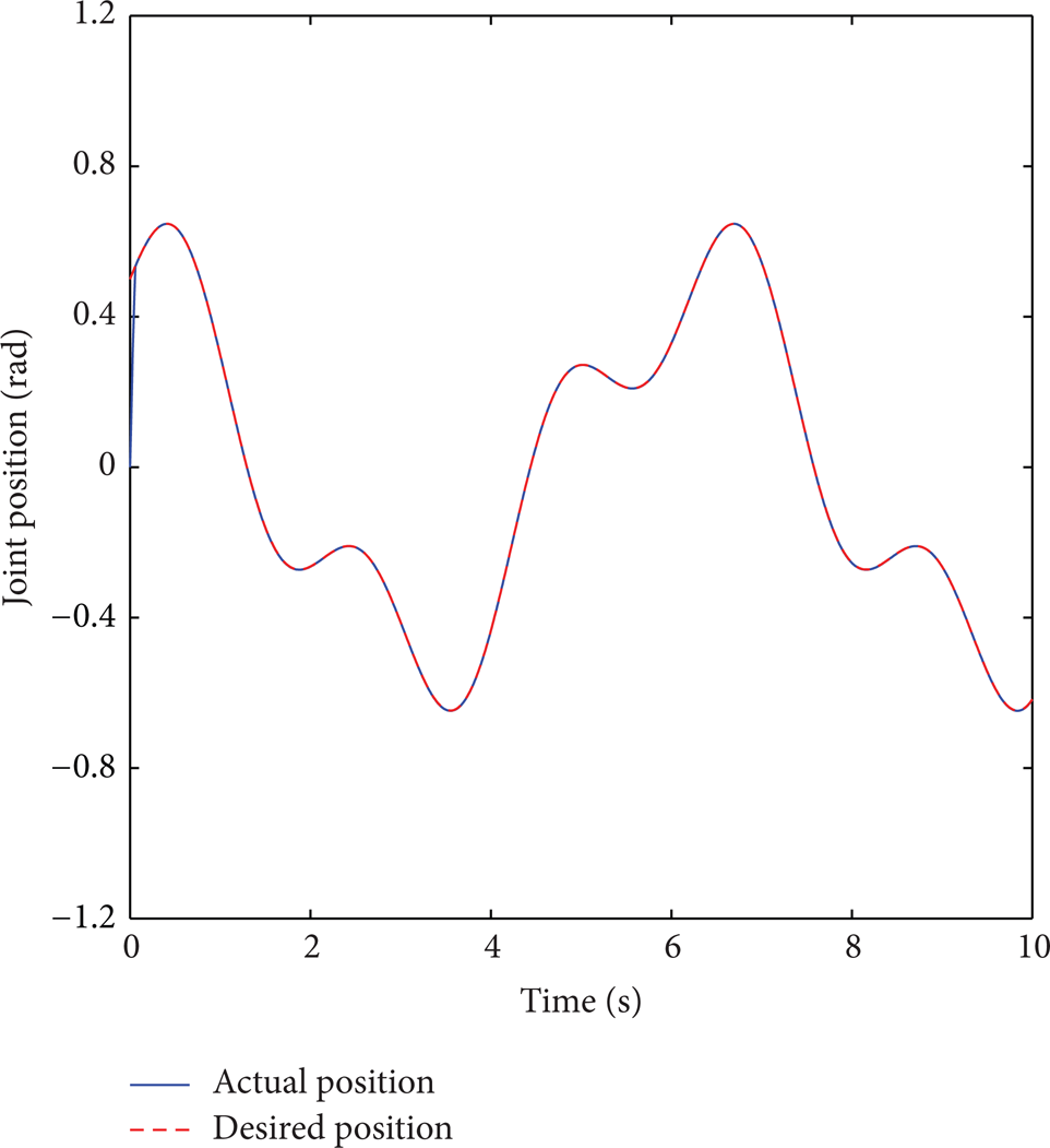
Joint 1 position tracking curve of configuration A under VGSTA based INSMC.

Joint 2 position tracking curve of configuration A under VGSTA based INSMC.

Joint 1 position error curve of configuration A under VGSTA based INSMC.

Joint 2 position error curve of configuration A under VGSTA based INSMC.

Joint 2 position tracking curve of configuration B under VGSTA based INSMC.
Joint 2 position error curve of configuration B under VGSTA based INSMC.
Figures 19 and 20 have shown the end-effector constrained force curves, and Figures 21 and 22 have shown the 3D end-effector trajectory tracking curves of the two different configurations under the VGSTA based INSMC. From these figures, we can conclude that when the external constrained force is exerted on the end-effector of the MRR with different configurations, the end-effector desired trajectory can be tracked accurately under the proposed VGSTA based INSMC.

The end-effector constrained force curve of configuration A.

The end-effector constrained force curve of configuration B.

The 3D end-effector trajectory tracking curve of configuration A under VGSTA based INSMC.

The 3D end-effector trajectory tracking curve of configuration B under VGSTA based INSMC.
Comparing the simulation results, we can see that the MRR system can achieve the asymptotic attractiveness of the sliding manifold in finite time with the designed sliding surface, and the model uncertainty can be compensated accurately under the proposed VGSTA based INSMC.
5. Conclusions
This paper presents a novel decentralized integral nested sliding mode control approach to address the problem of joint trajectory tracking control of a time varying constrained MRR with strongly coupled model uncertainty. The dynamic model of the time constrained MRR is described as a synthesis of interconnected subsystems. Based on only local dynamic information of each module, a decentralized integral nested sliding mode control approach is proposed to reduce the chattering effect of the controller and compensate the model uncertainty. The stability of the close-loop system is proved using the Lyapunov theory. The simulation results have confirmed the effectiveness of the proposed method.
Conflict of Interests
The authors declare that there is no conflict of interests regarding the publication of this paper.
Footnotes
Acknowledgments
This work is financially supported by the National Natural Science Foundation of China (Grants no. 61374051 and 60974010) and The Scientific Technological Development Plan Project in Jilin Province of China (Grant no. 20110705). The first author is also funded by China Scholarship Council.