
Abstract
The energy saving and electricity safety are today a cause for increasing concern for homes and buildings. Integrating the radio frequency identification (RFID) and ZigBee wireless sensor network (WSN) mature technologies, the paper designs a smart control strategy to implement an intelligent energy safety and management system (IESMS) which performs energy measuring, controlling, monitoring, and saving of the power outlet system. The presented RFID and billing module is used to identify user, activate smart power outlet (SPO) module, deduct payable for electricity, and cut off power supply to the outlets by taking away the RFID card. Further work on the SPO module, a control strategy based on the minimum effect and first-in first-out rule, is designed to autonomously shut down some of the power outlets instantly to prevent electrical circuit overload. In addition, the WSN transfers the power parameters of each SPO module to central energy monitoring platform, and the monitoring platform with graphical user interface (GUI) displays the real-time information and power charge of the electricity. Numerous tests validate the proposed IESMS and the effectiveness of the smart control strategy. The empirical findings may provide some valuable references for smart homes or smart buildings.
1. Introduction
The world population is rapidly ageing. According to the World Health Organization (WHO) in 2012, the proportion of elderly population over 60 years old will double from about 11% to 22% between 2000 and 2050. In addition, around 4%–6% of older people in developed countries have experienced some form of maltreatment at home. Creation an aged-friendly environment and safety living is today an attractive issue. The smart home or smart building concept, of course, is a promising and cost-effective way to the problems. The popularity of home automation has been increasing greatly in recent years due to much higher affordability and simplicity through network connectivity [1–5], but its current status is not matured [1].
Fires in residences have taken a high toll of life and property. US Fire Administration indicated that there were 362,100 residential building fires, 2,555 civilian fire deaths, 13,275 civilian fire injuries, and around $6.6 billion in property damage in 2010. Overloaded electrical appliances, frayed wires and extension cords, and blown fuses are the most common causes of house fires. A no fuse breaker (NFB) or called molded case circuit breaker (MCCB) is a plastic protective device that interrupts a current if the current exceeds the trip rating of the breaker. The NFB is installed in the low voltage circuit to protect electrical equipment from overload and short circuit. On the overload trip operating characteristics, even though the NFB trips, the operating circuit may be overheat already. In fact, over 80% electrical fires start below the safety threshold of NFB. NFB could not guarantee the energy safety. Additionally, long-term overload of the NFB may cause aging mechanism, contact fault, or delay trip which always results in electrical fires for the NFB failure. Once the NFB trips; furthermore, it would cause the major power outages or electricity blackouts that are very costly for energy providers and very uncomfortable for users. How to reduce the region of power outage and prevent fire suffered from overload appliances is also the concern of the work.
Standby power is electricity used by appliances and equipment while they are switched off or not perform their primary functions. In 2007, International Energy Agency (IEA) pointed out that advanced country families did not pull the plug and wasted standby power, accounting for about 5% to 10% of the total electricity consumption. The standby power for every family was nearly 30 kWH monthly and resulted in carbon dioxide (CO2) emission of 16 kg. Moreover, the standby power was responsible for roughly 1% of global carbon dioxide emissions. This is a serious threat for energy crisis and greenhouse effect. The utilization of renewable energy resources [6] and the development of efficient energy management [7, 8] are the key solutions to these problems.
Power outlets or power sockets are probably the most commonly used electrical devices in modern home environments. Unlike conventional power outlets, smart power outlets could measure and monitor consumption electricity and control ON/OFF states of the electrical appliances. The smart power outlets have recently emerged as a new paradigm for home energy management that can autonomously control electrical appliances and especially provide safety electricity environment. The needs of finding a smart and intelligent power outlet are increasing concern [9].
Currently, consumption electricity is a rather complex issue for the end-user. The values of consumption electricity are hidden from the user. One is never aware which device contributes to it to which amount. Consequently, the visualization of power consumption data of electrical appliances for enhancing energy-awareness is becoming increasingly important.
In recent years, the design of efficient energy management system for homes or buildings is an active field of research. With the advance of microelectromechanical system and wireless communication technology have led to great progress in radio frequency identification (RFID) [10–13] and wireless sensor network (WSN) [5, 8, 13–15]. Among the various applications, energy management is probably the most important one to be addressed. Elzabadani et al. [16] presented an intelligent way to sense new devices installed in a smart space. As a result, it can identify and monitor any load, but it is unable to collect power information. Song et al. [17] constructed a ZigBee-based power outlet for smart homes, but it did not measure power consumption. Abe et al. [18] proposed a ZigBee-based smart power outlet network for gathering power consumption data. However, the presented energy management system does not provide any protection in an emergency. Based on the ZigBee communication and infrared remote control, Han et al. [19] proposed a system that performed active control for reducing standby power using sensor information. The study lacks overload detection and protection. Huang et al. [20] constructed a ZigBee-based monitoring system with self-protection. The work equipped each power outlet with an energy metering IC to calculate power parameters from the outlet. It created more complex circuit structure and higher device costs. In addition, they just focused on two outlets protection in a branch.
Energy management system is the integration of technologies and services through home networking for an intelligent living environment. In view of the energy conservation and energy safety trends, the paper presents a valuable approach to this issue. The intelligent energy safety and management system (IESMS) is proposed to lower CO2 emissions and higher electricity safety by reducing end-user consumption electricity and preventing electrical circuit overload. Compared to the existing related research [17–20], there are some key features concerned with the work.
Using household appliances, the user needed to be identified and obey user-pays principle by means of the RFID and billing module. The payment mechanism may motivate user to save energy. Using the minimum effect and first-in first-out rule, a smart control strategy is designed to realize energy-aware coordination of the household appliances and to implement the IESMS. A microcontroller (MCU) programming is developed to secure four power outlets in an electrical loop from overload and ensure home against fire. The paper constructed a SPO module with only an energy metering IC to measure and calculate power consumption of each of the four power outlets by a multiplexer. Compared with the literature [20], expenses were reduced. Moreover, the work developed a smart control strategy to exercise control over the four power outlets in an electrical loop. To achieve further energy efficiency, all the power outlets would be automatically shut down while user was taking away the RFID card. Consequently, there is no standby power consumption of the household appliances.
The results of the study may be useful to researchers attempting to develop smart homes or smart buildings. Furthermore, the IESMS can be applied to the service apartment or dormitory.
The remainder of the paper is organized as follows: the system architecture and operation is explained in Section 2. Section 3 describes the functions of RFID and billing module. SPO module is developed and implemented in Section 4 in detail. Section 5 proposed a smart control strategy that performs overload detection and protection. Numerous experimental results are presented in Section 6. Finally, Section 7 presents the conclusions for the work.
2. System Architecture and Operation
The capability of power controlling, monitoring, and energy safety is indispensable to power management. The section presents the architecture for realizing the IESMS based on the user-pays principle. Figure 1 depicts the applied IESMS for a building. The RFID and billing module, SPO module, and ZigBee WSN transmission module were installed in each room. The supervisor could access the electricity status through the ZigBee WSN and by the graphic user interface (GUI), which is performed in central energy monitoring platform. The IESMS operation is described as follows.

Applied IESMS for a building.
First, the RFID and billing module could control user access and control on or off the power outlets. In addition, the module would complete the user-pays claim and shut down power outlets automatically as user leaves the room and takes away the RFID card. As a result the standby power consumption of the household appliances is saving.
Second, the SPO module is the critical module of the whole system since power measurements and overload protection are integrated within SPO. It is an autonomous low voltage overload control that can provide power system operation safety. The power outlet system comprises four receptacles each with voltage/current sensing and control action, energy metering IC for energy measurement, a 16-bit MCU for implementing safety operation, and ZigBee WSN module for transmitting the related data to central energy monitoring platform. The SPO module detected the power parameters anytime while a household appliance plug was put in the power outlet. Once the operating current of an electrical loop was over the set threshold, the control unit would shut down one or more of the power outlets based on the minimum effect and first-in first-out rule. Accordingly, a major power outage would not happen in the designed system.
Third, the ZigBee is a WSN standard based on the IEEE 802.15.4 and expected to have an explosive growth in remote control and monitoring applications because of its low cost and low power consumption. The work employed XBee-Pro Series 2 [21] that is designed for high power and long range transmission for the ZigBee WSN. The work used cluster tree network structure to connect other ZigBee devices on the network. The ZigBee end device was installed in each SPO module for transferring the power parameters to the central energy monitoring platform. Furthermore, the central energy monitoring platform has a lobby coordinator to collect all the data from floor routers, which are repeaters set in the staircase of each floor.
Finally, the central energy monitoring platform mainly consists of ZigBee lobby coordinator and displayer to accomplish the remote energy monitoring. The coordinator is the core of the whole ZigBee WSN, which is in charge of producing web beacon, collecting all the information generated by SPO module of each room, and coordinating the traffic of each floor router. All the collected information is stored in SQL (structured query language) server. The monitoring platform used visual basic (VB) as the interface software to provide a user-friendly environment. The GUI on the monitoring platform would display the real-time power parameters and power charge for each power outlet in an electrical loop. The operation flowchart of the system is illustrated in Figure 2.
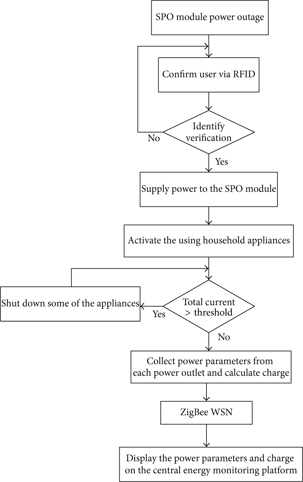
Operation flowchart of the IESMS.
3. RFID and Billing Module
RFID is composed of reader/writer and RFID tag. It is an automatic wireless identification technology that uses radio wave to transmit data and uniquely identify users individually according to their unique identifiers recorded in each RFID tag. The reader/writer is a device that receives signal back from the tag and writes data on the tag. If a user with RFID card enters a room, the RFID unit will recognize the user and then AC power supplies to SPO module. By the billing unit, the electricity bill will be deducted from the RFID card.
The work used the RFID reader/writer module Mifare RC522 [22] connected to Arduino Uno [23] to read/write the passive tag. The Arduino Uno is a MCU board based on the ATmega328. The RFID card was used to control user access and security, control power outlets ON/OFF, and implement the user-pays principle.
Figure 3 shows the control circuit with RFID and Arduino Uno for supplying power to SPO module. The work used solid state relay (SSR) instead of traditional relay for reducing power consumption. The RFID and Arduino module sends a high voltage to the

Control circuit for supplying power to SPO module.
4. SPO Module
The SPO module with an energy metering IC is designed to sense, measure, control, and monitor for each household appliance and to provide a safety feature in the form of overload protection. The SPO module was developed on the assumption that an electrical circuit provided four power outlets to be used in a room. Figure 4 shows the detailed block diagrams of the SPO module indicated units and their interactions. The SPO module consists of five units: the “DC power unit,” which supplies power to all the units of the SPO module; the “power parameters measuring unit,” sensing and measuring power parameters in real time and then sending them to MCU; the “MCU,” processing of the information from power parameters measuring unit and sending a control signal to control unit; the “control unit,” controlling the power outlet conditions ON/OFF; the “liquid crystal display (LCD) unit,” monitoring the consumption electricity and displaying the electricity bill. A brief description of the units is as follows.

Detailed block diagrams of the SPO module.
4.1. DC Power Unit
The power unit transfers AC 110 V to various DC powers and provides operating powers for the entire system. It delivers low voltage power 5 V to all the units in SPO module and LCD unit and provides power 3.3 V to ZigBee WSN room end device.
4.2. Power Parameters Measuring Unit
The unit provides sense and measure power parameters in real time and send out the messages to MCU for controlling and monitoring. As shown in Figure 4, the work used voltage divider and JCTP-80Z current transformer (CT) to sense the voltage and current of each power outlet. The CT is an electrical device whose output AC voltage is highly dependent on input AC current. It is a very sensitive current-measuring device. This fact is illustrated in the characteristic curve shown in Figure 5 [24]. It detects the current being used. Each of the current sensing signals is periodically sent to energy metering IC through a multiplexer. The energy metering IC ADE7763 [25] performs root-mean-square calculations on the sensing voltage and current and computes the active power consumed by each of the household appliances. All the real-time processing information needs sending to MCU via serial peripheral interface (SPI) bus.

Voltage-current characteristic curve of the JCTP-80Z.
4.3. MCU
The main part of the SPO module is the MCU that is a 16-bit dsPIC30F4011 [26] and contains built-in analog-to-digital converter (ADC), general purpose input and output (GPIO), universal asynchronous receiver and transmitter (UART), and SPI. The controller has extensive digital signal processor functionality, reading all the incoming measuring signals processed by energy metering IC, sending signals to control unit, ZigBee WSN, and LCD unit. According to the information about active power consumption, the MCU calculates the electricity bill and sends the message to Arduino Uno controller. Leaving the room, the user pays the bill by RFID card.
4.4. Control Unit
The unit was used to control the power outlet ON/OFF for protecting electrical circuit against overload. Figure 6 presents the hardware circuit of the control unit. In the beginning, the Reset button is pushed and the output Q is on LOW state. The AC power source line is connected to power outlet. Under normal operation, MCU sends a low signal to the D flip-flop, with the result that a low voltage on Q is fed into the NPN transistor. Both transistor and relay are cut off, and AC power source provides electricity to power outlet. However, depending on the control strategy, MCU will send some high signals to chosen control units to make the power outlets shut down instantly when the amount of working current is over the safety threshold.

Control power outlet ON/OFF.
4.5. LCD Unit
To monitor the power parameters of the household appliances, the LCD was connected to the GPIO of the MCU. The LCD unit employed a 4-bit data transmission mode.
5. Smart Control Strategy
A smart control strategy needs to be developed and programmed to become aware of any overload and to send out some signals to control units for controlling power outlets ON/OFF. The section presents the control algorithm to prevent circuit overload.
5.1. Safety Threshold Current for Overload Protection
The MCU dsPIC30F4011 has a built-in 10-bit high-speed ADC with four sample/hold devices and 500 ksps conversion rate. The maximum analog voltage is 5 V, then 1 V analog input can be converted to the digital value of [(210 − 1)/5 V] × 1 V = 204.6. By looking at the characteristic curve for CT (please refer to Figure 5), an AC 9 A current produces AC 1 V voltage with 100 Ω load. For the power line in an electrical loop was set by threshold current of 16 A in this work, the corresponding digital value was (16 A/9 A) × 204.6 = 363.73. The allowable digital value of 364 was thus chosen as the safety margin of the total consumption current for the studied SPO module. The safety threshold can be adjusted based on the rating current of the electrical loop.
5.2. Working Flowchart
The focus of our research was to propose a control strategy for the SPO module that was able to detect the total working current of the four household appliances with safety operation and overload protection in an electrical loop. The flow diagram of the control strategy in Figure 7 was used to show the sequence of the program execution, in which
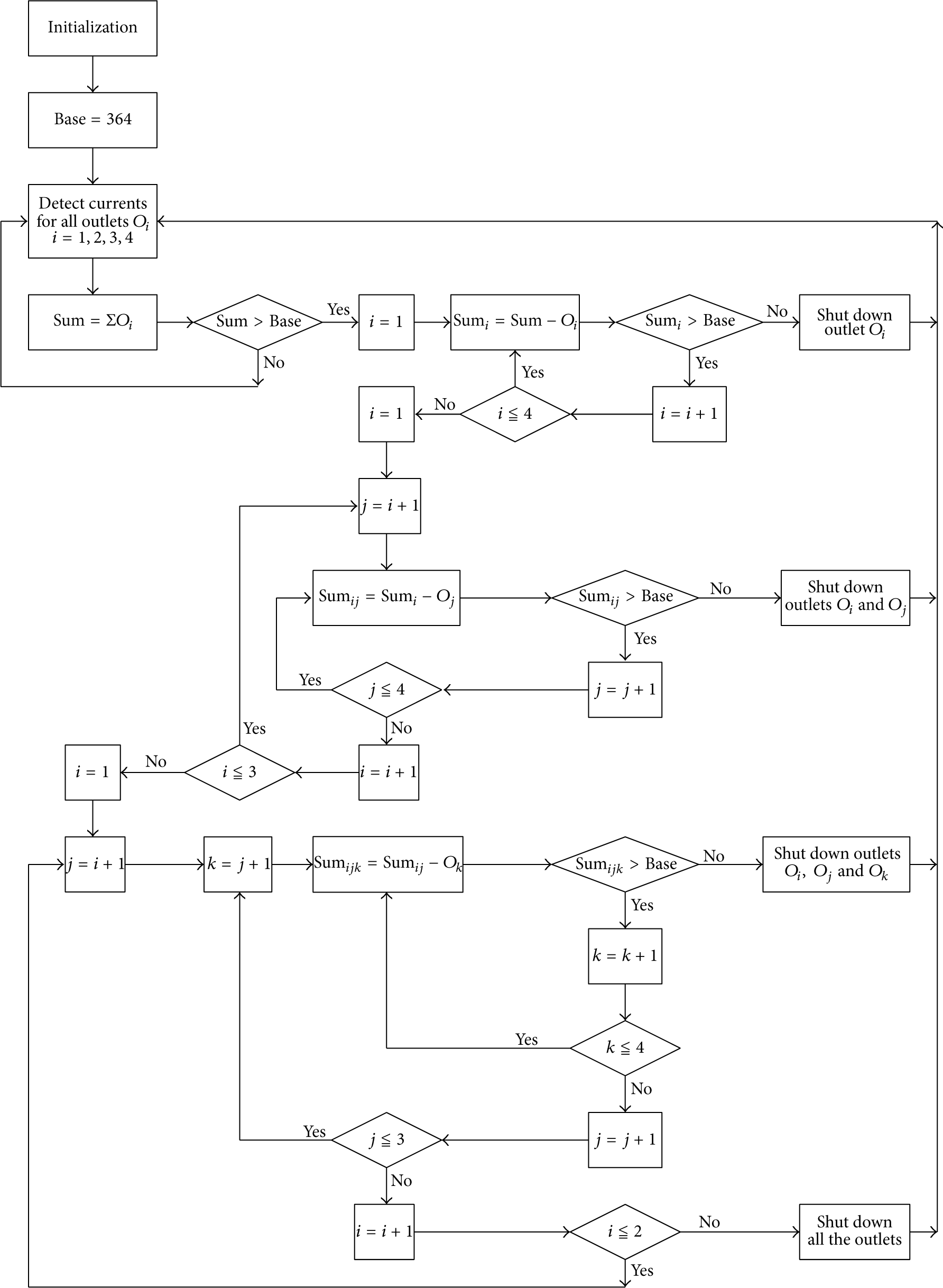
Flow diagram of the program execution for the control strategy.
6. Experimental Results and Validation
A prototype demo system with four power outlets was built in an electrical loop. Figure 8 shows the SPO module prototype for measuring, controlling, and monitoring of power outlets in a room. As mentioned in the preceding section, the total current consumed by household appliances with safety margin was set 16A. The MCU controls the power outlets ON/OFF by using the minimum effect and first-in first-out rule. To verify the feasibility of the control strategy and to illustrate the reliability of the proposed SPO, numerous experiment measurements and tests were made in the section.

SPO module prototype.
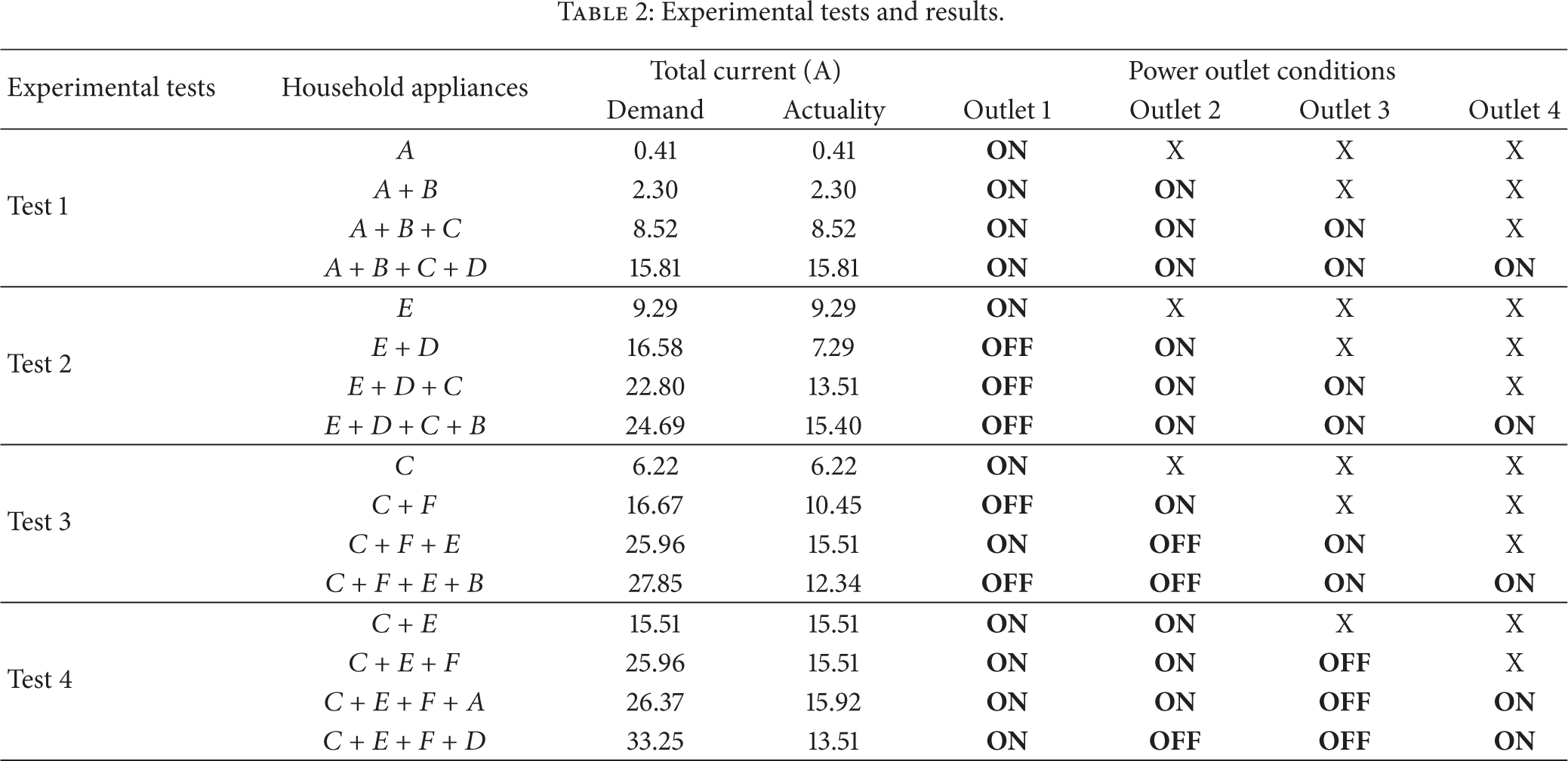
The list of the selected household appliances for the test is shown in Table 1. At first the user was needed to be identified via RFID unit. The electrical loop with four power outlets provided electricity for household appliances. Of the various tests evaluated, the experiments were executed on the assumption that the appliances were requested to plug in the power outlets from 1 to 4 in order. Table 2 shows the results with promising outcome. The cross “X” on the table is a symbol of unused power outlet. From Table 2, it was demonstrated to make sure that the proposed SPO module worked well, with regard to both hardware (modules of RFID and SPO) and software (execution of programs). Compared with the existing conventional power outlet, the designed power outlet made every home a smarter, safer and more energy efficient environment for consumers and families.
Household appliances to be tested in the work.

Experimental tests and results.
By the ZigBee WSN transmission, Figure 9 shows the GUI monitoring platform, in which it displays the real-time results of Test 1 and the use of household appliances
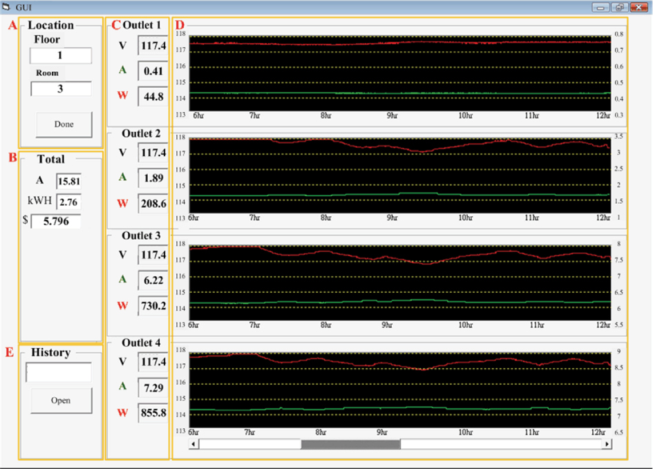
Test results shown on GUI monitoring platform.
7. Conclusion
The design of an intelligent electricity environment is becoming more important because of the concerns for the life and property. In the paper, an IESMS is developed for achieving effective energy management and electricity safety for buildings. By integrating the matured RFID and ZigBee WSN technologies, the paper proposes a smart control strategy and implements the IESMS. The control strategy executed in a microprocessor is designed to realize energy-aware coordination of the household appliances and to implement the IESMS. The primary module in the work is the SPO module. The module constantly measures the power parameters and exercise control over the power outlets in an electrical loop. Furthermore, it also ensures that the overload caused no damage to the infrastructure and does not trigger the circuit breaker. Finally, numerous experiment tests have been conducted to validate the effectiveness and feasibility of the proposed IESMS. The presented technology may be applied to the service apartments. The paper is expected to contribute the valuable results to the related researchers.
Footnotes
Conflict of Interests
The authors declare that there is no conflict of interests regarding the publication of this paper.