
Abstract
In the process of form grinding, gear setting error was the main factor that influenced the form grinding accuracy; we proposed an effective method to improve form grinding accuracy that corrected the error by controlling the machine operations. Based on establishing the geometry model of form grinding and representing the gear setting errors as homogeneous coordinate, tooth mathematic model was obtained and simplified under the gear setting error. Then, according to the gear standard of ISO1328-1: 1997 and the ANSI/AGMA 2015-1-A01: 2002, the relationship was investigated by changing the gear setting errors with respect to tooth profile deviation, helix deviation, and cumulative pitch deviation, respectively, under the condition of gear eccentricity error, gear inclination error, and gear resultant error. An error compensation method was proposed based on solving sensitivity coefficient matrix of setting error in a five-axis CNC form grinding machine; simulation and experimental results demonstrated that the method can effectively correct the gear setting error, as well as further improving the forming grinding accuracy.
1. Introduction
CNC form grinding machine is the most popular finishing machine for large-size gear because of its high accuracy, efficiency, and flexibility in tooth flank modification; however, the setting errors of gear and wheel induce tooth deviations in form grinding process. One major concern is how to improve form grinding accuracy; some scholars have done lots of primary work in studying mathematical model and error correction method.
Gear setting error is a common static geometric error in the process of form grinding. Some classic error modeling techniques for machine tools such as homogeneous transformation matrix (HTM), Denavit-Hartenberg (D-H) method, rigid body kinematics, and screw theory were reported in previous research works [1–3]. Park et al. [4] discussed a HTM method for geometric errors of a rotary axis of miniaturized five-axis machine tools, which developed the research foundation of this paper. In the relationship between machine error and form grinding error, Kobayashi et al. [5] established a mathematical model to estimate grinding wheel setting error in helical gear process by form grinding. Meanwhile, Schwenke et al. [6] proposed a method for geometric error measurement and compensation of machines. Besides, we have discussed the tooth profile deviations of gear profile grinding in relation to the eccentricity of grinding wheel [7, 8]. Gear setting error includes gear eccentric error, gear inclination error, and the phase of gear eccentric error; sometimes, those errors are coupling complex that make it difficult to obtain a precision error model. Therefore, it is significant to study the tooth deviations related to gear setting errors and propose a correct method to compensate the errors.
To compensate for the machining accuracy loss caused by gear setting errors, Shih and Chen [9, 10] derived an error model of a five-axis form grinding machine using reverse correction method. In recent years, with the rapid development of CNC machine tools, a real-time compensation technology is presented by Zhang et al. [11] and Uddin et al. [12], which break through the limitation of mechanical compensation and compensate the errors online by controlling the operation system.
The aim of this paper is to propose a correction methodology. For one thing, according to the gear standard of ISO1328-1: 1997 [13] and ANSI/AGMA 2015-1-A01: 2002 [14], the geometric error model with homogeneous transformation matrix (HTM) was established; the relation was obtained by changing gear setting errors with respect to tooth profile deviation, helix deviation, and cumulative pitch deviation, respectively, under the condition of gear eccentricity error, gear inclination error, and gear resultant error. For another thing, an error compensation method was proposed based on solving sensitivity coefficient matrix of setting errors in five-axis CNC form grinding machine. Simulation and experimental results demonstrated that the method can effectively correct the gear setting errors and further improve the forming grinding accuracy.
2. Mathematical Model and Evaluation for Tooth Deviation
Form grinding is a process that provides great potential with respect to flexibility and quality and can be used to grind a wide variety of gears. Grinding process on a five-axis CNC form grinding machine is presented in Figure 1; a profiled grinding wheel is used, which is swiveled to the helix angle of the gear and rotates to perform the cutting speed (A axis). In addition, the wheel must be able to move in a radial direction (X and Y axes) to remove stock form the flanks and in an axial direction along the gear axis (Z axis). If the gear is helical, it requires a continuous rotational movement in order to follow the lead and a discontinuous pitch movement (C and Z axis) to grind all teeth. However, because of the setting errors of the gears, it will result in tooth flank deviations in form grinding process. For example, the gear eccentricity error will lead to a large deviation of cumulative pitch deviation, the gear inclination error will lead to a large deviation of profile, and the gear resultant error will lead to a resultant deviation of helix and profile.

Grinding process on a five-axis CNC form grinding machine.
2.1. Coordinates Transformation in Homogeneous Matrix Representation
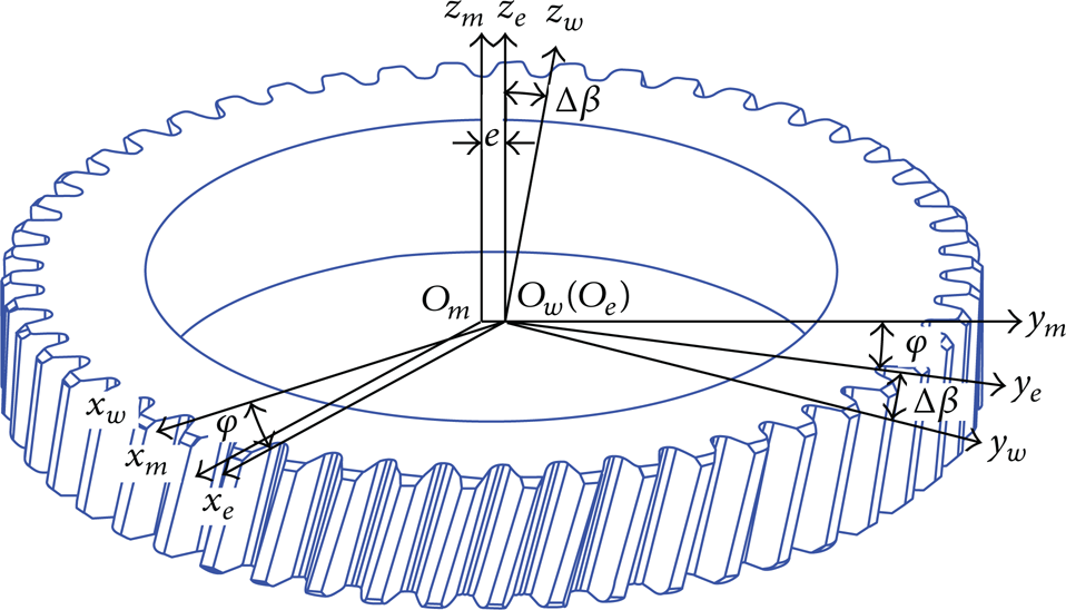
According to the multibody system theory, the pose of representative elementary volume B w is determined by coordinate transformation converts from its lower numbered body array B m . Consider that Cartesian coordinates O m -x m y m z m and O w -x w y w z w are established on the representative elementary volumes B m and B w ; the pose of coordinate O w -x w y w z w with respect to O m -x m y m z m can be represented by the homogeneous transformation matrix; see Figure 2.
Coordinate systems of form grinding.
With the influence of gear setting errors, gear has the angular errors {Δα, Δβ, Δγ} of three directions and three translational errors {Δa, Δb, Δc} along the coordinate axes when coordinate system O m -x m y m z m rotates or moves relatively to coordinate system O w -x w y w z w . Assume that all of them are microsmall amount and the sequence of gear rotation is independent. For simplicity, we simplify cosine and sine as symbols of “c” and “s,” respectively, so the homogeneous transformation matrix from coordinate system O w -x w y w z w to coordinate system O m -x m y m z m is presented as follows:

Due to the fact that {Δα, Δβ, Δγ} are the microsmall amount in gear setting errors, thus, Δk (k = α, β, γ) → 0, and cos Δk ≈ 1, sin Δk ≈ Δk. Ignore the higher-order infinitesimal; the homogeneous transformation matrix is represented by

Considering Δc is irrelevant to the initial grinding place of z-axes, and taking the intersection of standard surface and inclination surface as y-axes, that is, Δc = 0, Δγ = 0, and Δα = 0, so the transformation matrix is simplified as

where e, ϕ, Δβ are the eccentric error of gear setting, phase of eccentric error, and inclination error of gear setting, respectively. Assuming that the ending runout is t and the measure radius is r ce , the inclination error of gear setting Δβ is determined by atan (t/r ce ).
2.2. Mathematical Model
The equation of involute tooth surface of any flank i in coordinate system O m -x m y m z m is represented by [15]

where τ = ((i/z)2π + θ) ± (σ0 + u mi ), the symbol “±” indicates that the positive sign above represents right flank and the negative sign below represents left flank. r b is base radius.
σ0 is half of the angular tooth thickness on the base circle; u mi and θ are the surface parameter of screw involute surface; p is the screw parameter.
The tooth surface in gear coordinate system is represented by matrix equation

To simplify the calculation of tooth equation in different quadrant, the tooth profile equation is transformed into the first flank by comparing with the theoretical tooth flank; thus

According to the ISO standard 1328-1: 1997 for gear accuracy, tooth profile deviations and helix deviations are evaluated in transverse section, as is shown in Figure 3; tooth deviations of point e are determined by the normal distance ed between actual and theoretical tooth profile. Here, the formula for the point e with respect to theoretical tooth flank at d is given by

where

Illustration of tooth deviation evaluation.
Consequently, profile deviation, helix deviation, and cumulative pitch deviation can be derived by the aforementioned equation (7). Those evaluation terms include profile form deviation, ffα, profile slope deviation, fhα, helix form deviation, ffβ, helix slope deviation, fhβ, single flank deviation, ±f pt , and cumulative pitch deviation, F p . The profile form ffα, or helix form deviation ffβ, represents the distance between two facsimiles of the mean helix line, which are each placed with constant separation from the mean profile or helix line, so as to enclose the actual profile or helix trace over the evaluation range L; see Figure 4(a). The profile slope deviation fhα, or helix slope deviation fhβ, represents the distance between two design profile or helix lines which intersect the mean profile or helix line at the endpoints of the evaluation range L; see Figure 4(a). The single flank deviation, ±f pt , represents the displacement of any tooth flank from its theoretical position relative to the corresponding flank of an adjacent tooth. The cumulative pitch deviation, F p , represents the maximum measured transmission error range, during a single flank composite test, when the gear is moved through one revolution; see Figure 4(b).

Definitions of tooth deviations, (a) profile and helix deviation and (b) single and cumulative pitch deviation.
3. Gear Setting Error and Grinding Accuracy
3.1. Evaluation Method for Tooth Deviations
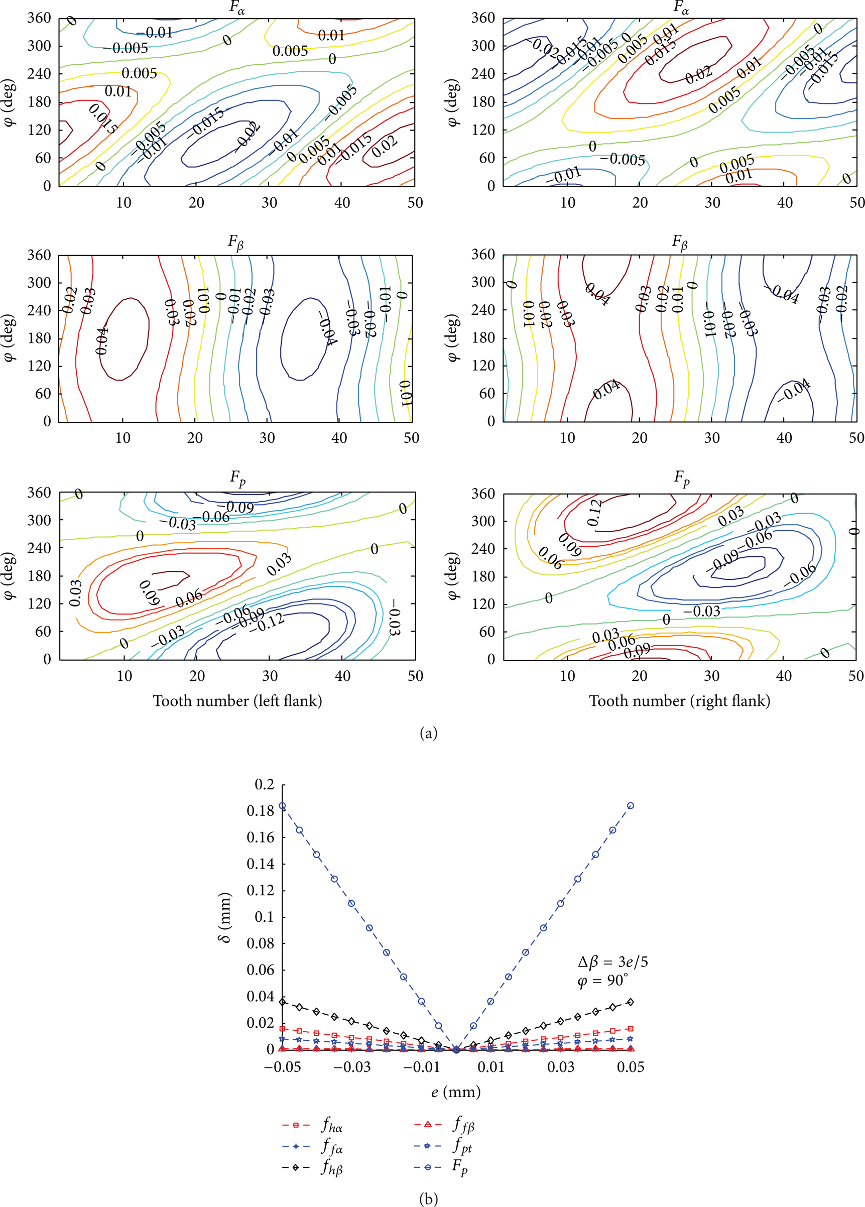
To obtain the variation of individual flank changing with the tooth number and the phase of gear eccentricity error, the tooth deviations are described as contour chart; see Figure 5. The coordinates on horizontal plane, respectively, represent the phase of gear eccentricity error, ϕ, and the numbered tooth, n z , in the 3-dimension chart, while the vertical coordinate represents different tooth deviation; see Figure 5(a). Section S 1 shows the total cumulative pitch deviations varying from tooth number when e is 0.05 mm, Δβ is 0.03° and ϕ is 80°, see Figure 5(b). Section S 2 , shows the cumulative pitch deviations varying from the phase of eccentricity error when the tooth flank number is 40.

Illustration of tooth error evaluation.
Recalling from the transformation matrix, gear eccentricity error, e, gear inclination error, Δβ, and the phase of gear eccentricity error, ϕ, should be taken into account in analyzing the sensitivity error in terms of tooth deviations. So the results of individual error are discussed by an orthogonal experiment of numerical simulation.
Take a helical gear, for example, number of teeth 50, module 10 mm, pressure angle 20°, helix angle 15°, face width (axial) 50 mm, gear eccentricity error 0.05 mm, and gear inclination error 0.03°.
3.2. Grinding Accuracy under Gear Eccentricity Error
Figure 6 shows the relationship between gear eccentricity error and tooth deviations. As is shown in Figures 6(a) and 6(b), profile slope deviation and total cumulative pitch deviation are sensitive to gear eccentricity error, profile slope deviation is less than e/4 (0.012 mm), and total cumulative pitch deviation is equal to 2e (0.1 mm). However, the total helix deviation (<0.005 mm) and the profile form deviation (<0.001 mm) are insensitive to gear eccentricity error.

(a) Relationship between gear eccentricity error and tooth deviations; (b) relationship between gear eccentricity error and the maximum tooth deviations.
3.3. Grinding Accuracy under Gear Inclination Error
Figure 7 shows the relationship between gear inclination error and tooth deviations. As is shown in Figures 7(a) and 7(b), helix slope deviation (0.040 mm) and cumulative pitch deviation (0.084 mm) are sensitive to gear inclination error. However, the total profile deviation (<0.001 mm) and helix form deviation (<0.001 mm) are insensitive to gear inclination error.

(a) Relationship between gear inclination error and tooth deviations; (b) relationship between gear inclination error and the maximum tooth deviations.
3.4. Grinding Accuracy under Gear Resultant Error
Figure 8 shows the relationship between gear resultant setting error and tooth deviations. As is shown in Figures 8(a) and 8(b), with the change of eccentricity error phase, both eccentricity error and inclination error contribute to the fluctuation of the maximum tooth deviations. Particularly, on the phase of ϕ = 90°, the tooth deviation reaches to the maximum on the left flank that they can be considered as linear superposition of individual setting error. However, the maximum tooth deviation is on the contrary on the right flank. Thus it can be seen that the phase of eccentricity error generates the diversity of tooth deviations on both flanks; while one flank comes to the maximum error, the other will be compensated.
(a) Relationship between gear resultant error and tooth deviations; (b) relationship between gear resultant error and the maximum tooth deviations.
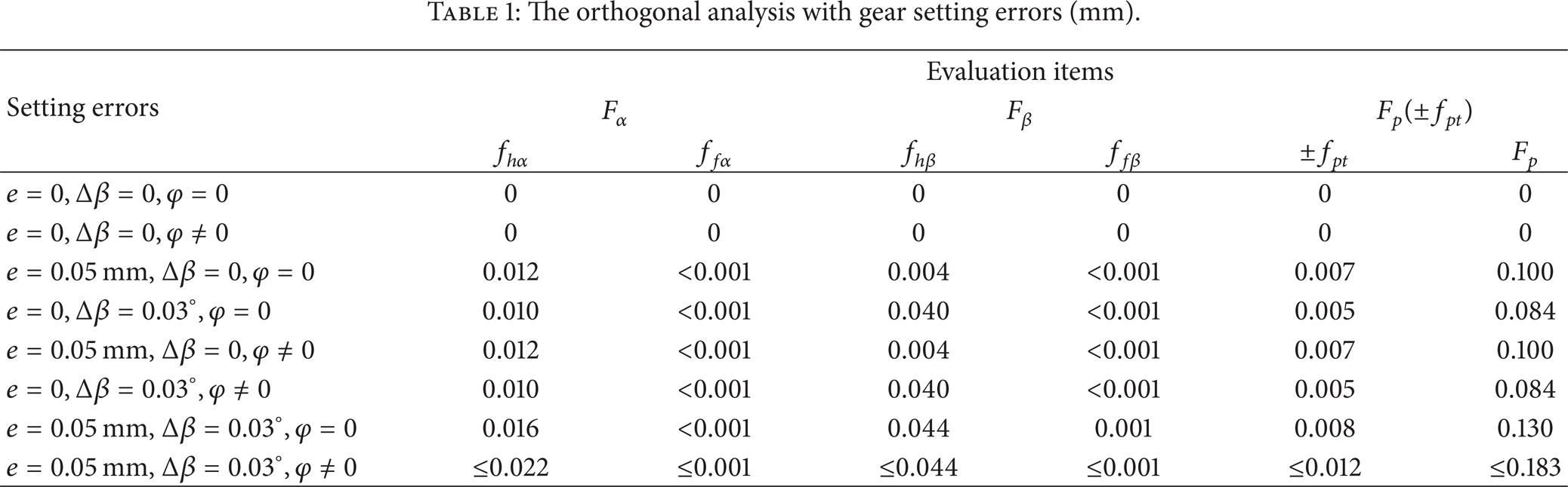
In the numerical example, the tooth deviations are obtained using the orthogonal analysis method and the results in Table 1 are concluded by the following.
The tooth deviations are linear correlation to the individual tooth deviation of different setting error, such as gear eccentricity error, gear inclination error, and gear resultant error.
While the gear eccentricity error has a large impact on the cumulative pitch deviation, nearly 2e, the inclination error of gear setting will twist the helix and cause helix deviations.
In particular case of the gear eccentricity error only, tooth deviations keep constant even if the phase of maximum deviations changes with the phase of gear eccentricity error. However, the inclination error is unrelated to the phase of gear eccentricity error.
The diversity of tooth error is mainly influenced by the phase of gear eccentricity error under the gear resultant error; in particular, when the phase of gear eccentricity error is 90 degree, the total tooth deviation can be considered as the superimpose of those deviations caused by gear eccentricity error and gear inclination error.
The orthogonal analysis with gear setting errors (mm).
4. Compensation Method by Solving Sensitivity Coefficients Matrix
Since Gleason-Pfauter delivered its first profile grinding machine in 1984, modern sophisticated CNC machines like Hofler's Rapid and Niles's ZP series machines have developed improvements and enhancement such as integrated grinding wheel dressing, on-machine gear precision evaluation, and error compensation with a multispindle linkage control. It is possible to accomplish the movement with the linkage axes of Y, A, and C, to correct the setting errors. So we propose an error compensation method based on solving sensitivity matrix with respect to the polynomial coefficients. Compared with the traditional error compensation method, such as the hardware motion compensation and the machine adjustment compensation, the proposed method is of high precision and is simple by the software compensation; besides, it is easily achieved through direct control of the CNC axis motion.
4.1. Assumptions
Recall that the total deviations of tooth satisfy the principle of linear superposition with respect to individual tooth deviation of different setting error. Besides, the trend of tooth deviation, which is produced by the phase of gear eccentricity error, ϕ, is quite opposite in right flanks and left flanks, respectively. Consequently, to simplify the algorithm of compensation, it should be assumed as follows.
Assume that the total deviation of tooth satisfies the principle of linear superposition with respect to individual tooth deviation of different setting error.
Regardless of the influence of eccentricity phase, the larger error among the measured data by on-machine gear measurement or simulation will be chosen as the objective of correction.
4.2. Solving Sensitivity Coefficients Matrix
From the above-mentioned assumptions, the total deviation of single setting error can be considered as a linear superposition of individual deviation of microsmall error, so the tooth variation vector is as follows:
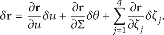
Because vectors ∂
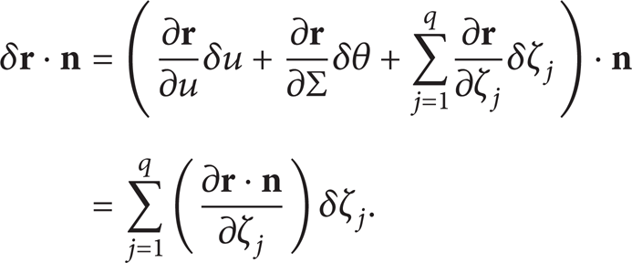
The normal tooth variations at the topographical grid points may then be written in matrix form [9, 10]:

where
The steps of the method are as follows.
Constructing the sensitivity matrix [
Obtain the tooth deviations {
Solve the compensations δζ j (ΔY, ΔA, ΔC) by using linear regression method. Because the number of polynomial coefficients j is smaller than the number i, so (10) is overdetermined; the compensations can be approximated using a linear regression technique like the least squares method:

Correct the tooth deviation by the derived compensations δζ j (ΔY, ΔA, ΔC) to control the machine operation system.
A numerical example applies the proposed compensation method to correct the tooth deviations. The actual tooth deviations {
Part of the calculation results in solving sensitivity coefficients matrix.

Subsequently, based on the calculated compensations, the machine parameters are adjusted in form grinding process. Figures 9(a) and 9(b) show the simulated tooth deviations of main terms for gear accuracy measurement before and after correction, respectively. As the graphs illustrate, the proposed compensations method efficiently reduces the tooth deviations caused by the gear setting errors.

(a) Tooth deviations before correction; (b) tooth deviations after correction.
5. Experiment Example and Discussion
To verify the validity of the proposed method, a five-axis CNC gear form grinding machine is investigated to compensate the setting errors in the process of grinding; see Figure 10(a). The basic parameters for the gear form grinding in the experiment example are listed in Table 3. The radial runout is given by 0.1 mm; that is, the eccentric error is equal to 0.05 mm. While the ending runout is given by 0.135 mm, that is, the gear inclination error, Δβ, is equal to 0.03°. Note the maximum and minimum radial runout as the number 1 tooth flank and the number 25 tooth flank, respectively. Then a ninety-degree angle clockwise with the first tooth flank is marked as number 17, and the anticlockwise one is marked as number 37. The machining precision is evaluated by the gear standard of ISO1328-1: 1997 and the ANSI/AGMA 2015-1-A01: 2002.
Basic parameters for the gear form grinding process in the experiment.


Experiment of form grinding, (a) gear form grinding; (b) on-machine measurement.
After the grinding is completed, we select tooth space numbers 1, 13, 25, and 37 as the measurement flanks; then, all the customary gear evaluation characteristics, such as profile deviation, helix deviation, and cumulative pitch deviation, can be measured and displayed in both graphical and numerical form by the on-machine measurement; see Figure 10(b).
Figure 11 shows the results before compensation; on the left flank, the accuracy of tooth number 1 is grade 9 for profile deviation (27.2 μm), the accuracy of tooth number 37 is grade 10 for helix deviation (38.8 μm), and the cumulative pitch deviation is grade 10 (184.6 μm), while on the right flank, the accuracy of tooth number 1 is grade 4 for profile deviation (5.1 μm), the accuracy of tooth number 37 is grade 11 for helix deviation (44.7 μm), and the cumulative pitch deviation is grade 10 (20.6 μm). Figure 11 demonstrates gear eccentricity error and gear inclination error leads to the diversity of tooth error; some of the tooth deviation can be considered as the superimpose of the resultant error; others are the subtraction of the resultant error. In the second, the cumulative pitch deviation is sensitive to the gear resultant error. Regarding the uncertain factors in form grinding process, the tooth accuracy on both right and left flanks is consistent with those of the simulated results above.

Machining result before compensation.
Figure 12 shows the results after compensation by the proposed correction method. According to the graphs, the accuracy on both the right and left flanks is grade 4 or higher, whereby the deviation of profile is 7.2 μm, the deviation of helix is 6.1 μm, and the deviation of cumulative pitch is 18.6 μm. In comparison with Figure 11, the accuracy of profile deviation, helix deviation, cumulative pitch deviation is improved from grade 9, grade 11, and grade 10 to grade 4, respectively. Consequently, the results verify the validity of the proposed method by improving the gear accuracy of form grinding.

Machining result after compensation.
6. Conclusions
The above studies show that the gear setting errors can be corrected by the proposed compensation method, and the following conclusions are drawn.
The total deviations of tooth are linear related to the individual tooth deviation of different setting error. The eccentricity error of gear setting has a large impact on the cumulative pitch deviation; the cumulative pitch deviation is almost twice the eccentricity error. Besides, the inclination error of gear setting twists the helix and causes a helix deviation.
The diversity of tooth error is mainly influenced by the phase of gear eccentricity error under the gear resultant error; in particular, when the phase of eccentricity error is 90 degrees, the total deviation can be considered as the superimpose of gear eccentricity deviation and gear inclination deviation.
Gear setting errors can be corrected by the compensation method of solving the sensitivity coefficient matrix, and the simulation and experiment results proved the effectiveness of the proposed method in five-axis NC form grinding machine.
Footnotes
Nomenclature
Conflict of Interests
The authors declare that there is no conflict of interests regarding the publication of this paper.
Acknowledgment
The authors are grateful to the National Natural Science Foundation of China (no. 51175242).