
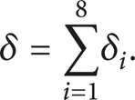
Abstract
High positioning accuracy with odometer wheel is of great importance for internal pipeline defect detection. In current research, the qualitative analysis is focused on and the accumulation characteristics of positioning errors are not shown. Based on this, the models and the accumulation characteristics of positioning errors are investigated in this paper. The errors are classified into systematic errors and random errors. Systematic errors consist of difference between actual and nominal diameters, diameter difference among wheels, and terminal error. Random errors consist of initial point error, weld error, and oversized clearance. The mathematical models of the errors are obtained by the methods of quantitative analysis and contrastive analysis. Through calculation examples, the results show the relationship of the errors and the effect of each error on total error. Diameter calibration and detection in sections are proposed to improve the positioning accuracy.
1. Introduction
In recent years, following the increase of the service time of oil and gas pipelines, there have been various problems arising gradually on pipelines. Then the technology of pipeline defect detection comes into being [1–6].
At present, pipeline defect detection has been divided into two main branches, that is, external pipeline defect detection and internal pipeline defect detection. Moreover, the internal pipeline defect detection consists of the positioning and the attribute identification of the defects [7].
Odometer wheel, the component of the detection device, is one of the basic methods for internal defect positioning. In order to improve the positioning accuracy, factors that affect it should be analyzed systematically.
2. Positioning Mechanism of Odometer Wheel
In the process of internal defect detection, the odometer wheel rolls along the pipe wall, and the movement of the odometer wheel and the detection device always stay the same [8]. When odometer wheel rolls forward, the relative movement between the magnet installed on the odometer wheel and the hall element installed on its arm sends out pulse signal. In engineering practice, each wheel is installed with 3 magnets at equal intervals, which makes the pulses have the same duration. For every 2π/3 the wheel rotates, the small magnet and the hall element work together to send out one pulse signal [8, 9], and there are 3 pulse signals when the wheel rolls a circle.
The pulse signals received by RB interface of the single-chip will be converted into digital signals, which are recorded by the counter and stored in the memory [8]. The distance traveled by the wheel between two adjacent pulses is one-third of the wheel perimeter. Multiplying it by the signal number, the distance is obtained as follows:

where S is measured distance, N is pulse signal number, and D is odometer wheel diameter.
3. Error Factors of Odometer Wheel
In the process of positioning, the error will be accumulated with continuous rotation of the odometer wheel [10, 11]. If the result contains a large error in positioning, the volume and time of the excavation of pipeline maintenance will be greatly increased [12–14]. Therefore, in this paper, the various factors causing positioning error with the odometer wheel are analyzed in order to improve the accuracy. The errors are classified into two main categories: systematic error and random error.
3.1. Systematic Error
The systematic errors, which are due to the following reasons, are mainly affected by positioning characteristics and the construction of the odometer wheel.
3.1.1. Difference between Actual and Nominal Diameters
In engineering practice, the nominal diameter of the steel odometer wheel is 145 mm [8]. However, because of the limitation of the production technology, there is difference between the actual and the nominal diameters. In addition, the causes of the difference can also be the following: the error of the measuring tool, the accidental error of approximate reading, the changing of steel equipment affected by temperature, and so forth. In these cases, the number of the stored pulses is not equal to the real number.
3.1.2. Diameter Difference among Wheels
To improve the positioning accuracy, the detection device is equipped with 4 odometer wheels [15]. If the diameters are not the same, the wheel with smaller diameter will lose contact with the internal surface of the pipeline. In this case, the number of pulse is less than the real number and the measured distance is shorter than the real distance.
3.1.3. Terminal Error
When the wheel rotates less than the angel of 2π/3, the terminal error caused by the counter increases with the wheel rotating from 0 to 2π/3. When rotation angel reaches 2π/3, one pulse is sent out and the error of the counter is reset to 0. Similarly, the error increases again in the following periods of 2π/3. Thus, terminal error is in the end of the detection.
3.1.4. Center-Biased Detection Device
The difference between the actual and the nominal wheel intervals will lead to center-biased detection device when it rotates.
3.2. Random Error
The random errors, which are due to the following reasons, mainly result from the uncertainty of internal environment of the pipeline.
3.2.1. Initial Point Error
The initial point error, which is caused by the measurement error at the initial position of the detection device, is small. However, the error is an important factor that affects the high-precision positioning results.
3.2.2. Uneven Pipeline Internal Surface
When odometer wheel rolls through the uneven surface caused by corrosion, weld, and deposition, the uneven surface length is taken into account as pipe length, which leads to a great effect on positioning accuracy for long-distance detection.
3.2.3. Slippage of Odometer Wheel
The slippage caused by the deposition, such as wax and asphaltene, leads to the abnormal rotation. Therefore, the pulse frequency is abnormal and the positioning results contain a large error.
3.2.4. Inflexibility of Odometer Wheel
When there are impurities in the pipeline and the rotation of the wheel is limited, the wheel can easily get stuck and result in a great loss of the pulse signals.
3.2.5. Oversized Clearance
The clearance between the magnet and the hall element, which is greater than 0.5 mm, also causes the loss of the pulse signals, which leads to positioning error [8].
4. Mathematical Model and Accumulation Mechanism of Positioning Errors
4.1. Models of Systematic Error
4.1.1. Difference between Actual and Nominal Diameters
When the actual diameter is different from the nominal diameter, differential equation of the distance error δ1 is

where N is the stored pulse signal number which comes from the set of real numbers; D is odometer wheel diameter.
When dD is positive, the measured distance is greater than the real distance. Thus, the positioning error is positive. In contrast, when dD is negative, the measured distance is shorter than the real distance. Therefore, the distance error is negative.
4.1.2. Diameter Difference among Wheels
If the diameters of the 4 wheels are not the same, the wheel with smaller diameter will lose contact with the internal surface of the pipeline. If the wheel loses contact with the surface in the whole detection process, the number of pulse is zero.
In the detection process, the odometer wheel, which loses contact with the surface in earlier period, can have a normal rotation in the next period. Then it can lose contact with the surface again in the next period. In this case, the rotation of this wheel slows down, resulting in the number of stored pulse being less than that of the real pulse. The measured distance of this wheel is

where S1 is the measured distance of the wheel, which loses contact with the surface; N1 is the number of stored pulse signal of this wheel.
In the detection process, the distance error δ2 can be obtained by the following equation:

When the wheel loses contact with the internal surface, the pulse number decreases, resulting in measured distance being shorter than the real distance. Therefore, the distance error is negative.
4.1.3. Terminal Error
Terminal error, which is at the end of the detection, is a periodic function of 2π/3. Terminal error δ3 can be obtained by the following equation:
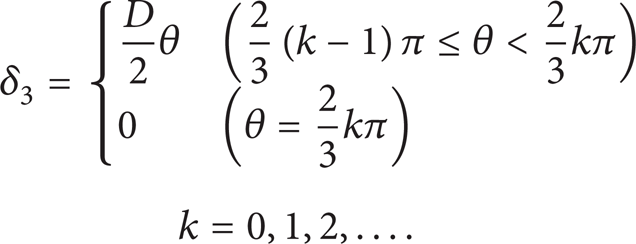
The terminal error of the positioning is as Figure 1 shows.

Counter positioning error diagram.
4.2. Models of Random Error
4.2.1. Concave Weld
When the weld is concave, the relationship among normal internal pipe surface L1, odometer wheel L2, and weld L3 is as Figure 2 shows. In this case, L2 is the covered distance of the wheel, resulting in measured distance being longer than the real distance. Therefore, the distance error is positive.
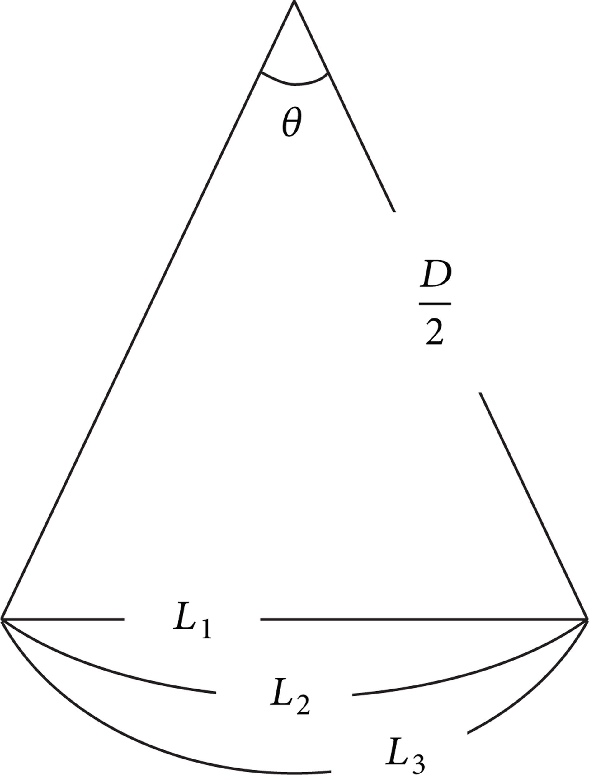
Relationship among normal internal pipe surface, odometer wheel, and concave weld.
The difference between the measured distance and the pipeline length can be obtained by the following equation:

Substituting Taylor formula into (6), the distance error δ4 is as follows:

where n is the number of the concave weld.
4.2.2. Convex Weld
The convex weld is as Figure 3 shows, where S is surface of the convex weld; L is straight line distance of the weld; f(L) is height of the weld. The trajectory of the wheel is S, while L is calculated in the measurement, resulting in positive distance error.
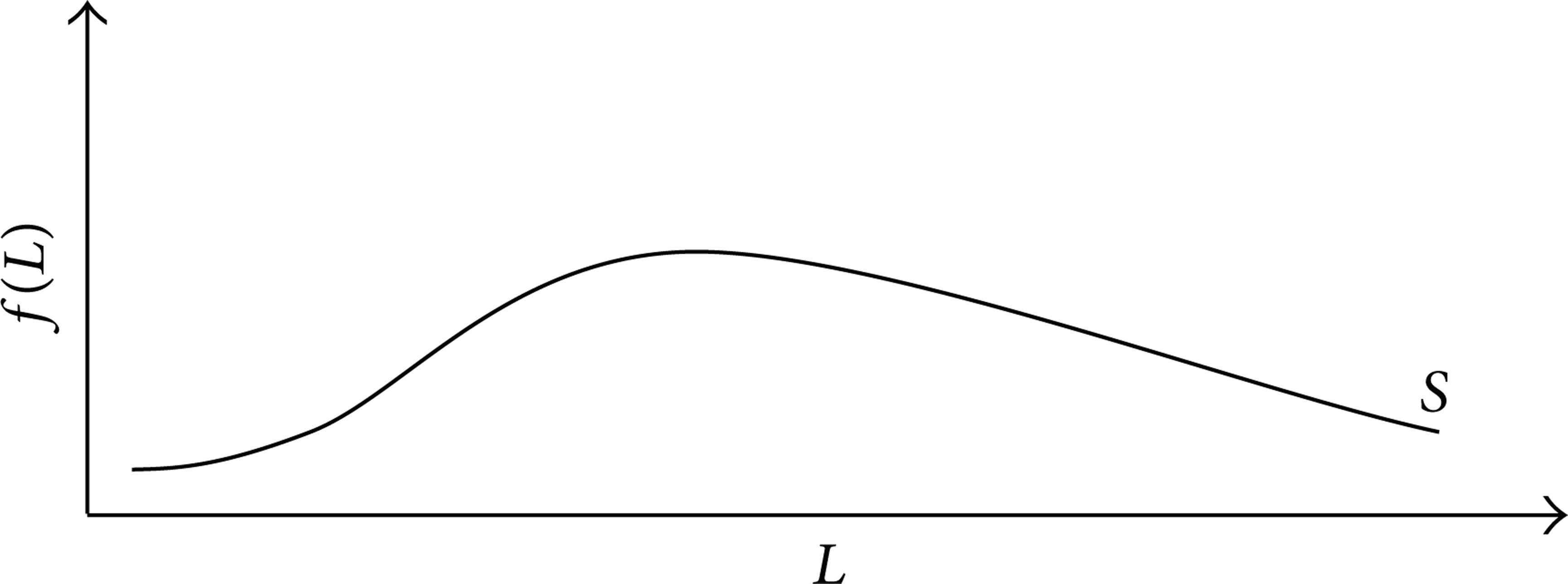
Convex weld.
The distance error δ5 between the measured distance and the pipeline length is as follows:

where n1 is the number of the convex weld.
4.2.3. Deposition
The positioning error of the odometer wheel caused by the deposition, which is on the pipeline internal surface, is analyzed under two situations.
(a) Even Deposition. The longitudinal profile of pipeline with even deposition is as Figure 4 shows. Because the deposition is even, the measured distance has no positioning error.
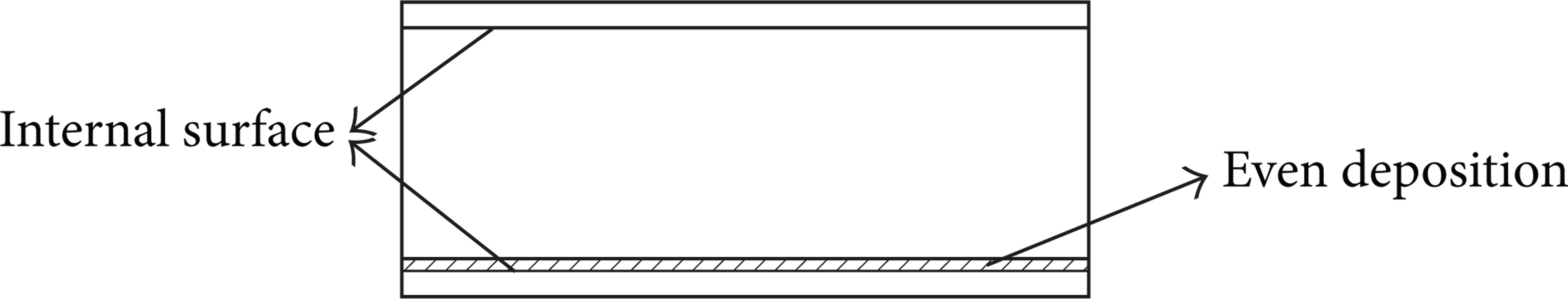
Longitudinal profile of pipeline with even deposition.
(b) Uneven Deposition. The longitudinal profile of pipeline with uneven deposition is as Figure 5 shows. When the deposition is uneven, the surface of the deposition is a curve, which is the trajectory of the wheel. In this situation, the measured distance is longer than real distance, resulting in positive distance error.

Longitudinal profile of pipeline with uneven deposition.
Mathematically speaking, the error caused by the uneven deposition is similar to the convex welds. The uneven deposition is as Figure 6 shows, where S is surface of uneven deposition; L is straight line distance of uneven deposition; f(L, t) is thickness of uneven deposition.

Uneven deposition.
The thickness of deposition can be obtained by the following equation:

where v(L, t) is the velocity of the deposition at the time t, in the point L.
Based on integral, the distance error δ6 between the measured distance and the pipeline length is as follows:

where the L1 and L2 are two points of the pipe.
4.2.4. Stuck Wheel and Oversized Clearance
The stuck wheel and oversized clearance cause pulse signal loss. Thus, measured distance is shorter than real distance, resulting in negative distance error.
If odometer wheel gets stuck in the whole detection process, the number of pulse is zero. In this situation, the detection device is considered as stopping working.
In the detection process, the odometer wheel, which gets stuck in earlier period, can have a normal rotation in the next period. Then it can get stuck again in the next period. In this case, the measured distance of this wheel is

where S2 is the measured distance of stuck wheel; N2 is the number of stored pulse signal of this wheel.
In the detection process, the distance error δ7 can be obtained by the following equation:

When the clearance between the odometer wheel and its arm is oversized, the pulse cannot be sent out. Therefore, the distance error δ8 caused by oversized clearance is similar to δ7.
4.3. Positioning Error Modeling
Mathematical models, accumulation characteristics, and error direction of error factors are listed in Table 1.
Contrastive analysis of error factors.
By summing up the above errors, the total positioning error δ is obtained as follows:
5. Calculation Examples
Due to small width of convex weld and being unable to obtain f(L), it is difficult for calculation by using the integral model in this paper. Thus, the distance error of convex weld is not calculated in the paper. The f(L, t), which is a function about time and location, is unknown, so distance error of uneven deposition fails to be calculated. The stuck wheel and oversized clearance have discontinuity and randomness. Therefore, their distance errors are not calculated in this paper. The calculation examples of other distance errors are as follows.
(1) Difference between Actual and Nominal Diameters. When the difference exceeds 1.5 mm, the wheel is replaced by a new wheel. The distance errors in the pipeline locations of 1 km, 2 km, 5 km, 10 km, 60 km, and 120 km are as Table 2 shows, where dD are 0.25, 0.50, 0.75, 1.00, 1.25, and 1.50 (unit: mm), respectively.
Distance error of difference between actual and nominal diameters.

From Table 2, the following laws can be obtained. (1) When dD is fixed, the distance error in 1 km is 1/2, 1/5, 1/10, 1/60, and 1/120 of the error in 2 km, 5 km, 10 km, 60 km, and 120 km, respectively. (2) When pipe length is fixed, the distance error, whose dD is 0.25, is 1/2, 1/3, 1/4, 1/5, and 1/6 of the error, whose dD is 0.50, 0.75, 1.00, 1.25, and 1.50, respectively. (3) The distance error increases with the increase of the pipe length and diameter error.
(2) Diameter Difference among Wheels. When the diameters of the wheels are different, the distance errors in the above pipeline location are as Table 3 shows, where dD is 0.25, 0.50, 0.75, 1.00, 1.25, and 1.50 (unit: mm), respectively.
Distance error of difference among wheels.
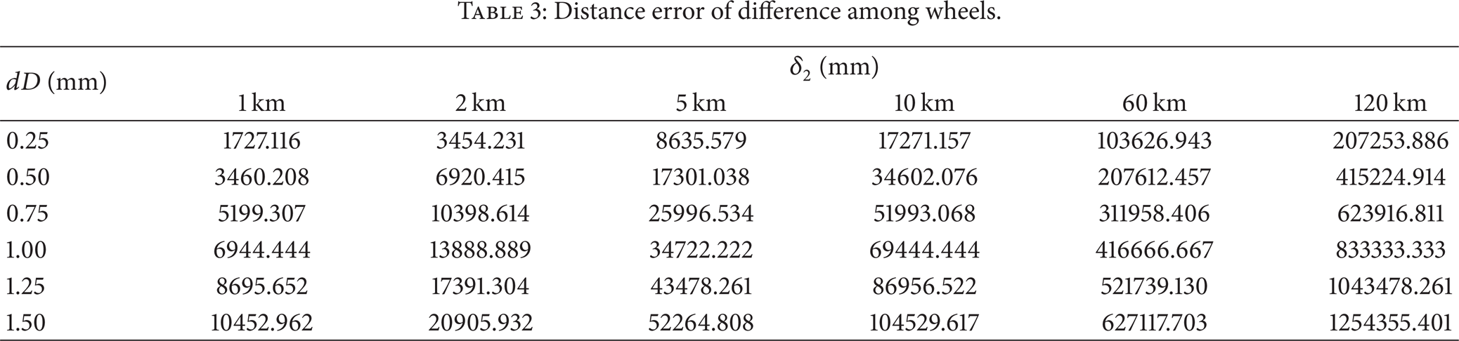
From Table 3, the following laws can be obtained. (1) When dD is fixed, the distance error in 1 km is 1/2, 1/5, 1/10, 1/60, and 1/120 of the errors in 2 km, 5 km, 10 km, 60 km, and 120 km, respectively. (2) When pipe length is fixed, the distance error, whose dD is 0.25, is 1/2, 1/3, 1/4, 1/5, and 1/6 of the errors, whose dD is 0.50, 0.75, 1.00, 1.25, and 1.50, respectively. (3) The distance error increases with the increase of the pipe length and diameter difference.
(3) Terminal Errors. The terminal errors in the above pipeline locations are as Table 4 shows.
Terminal error.

From Table 4, there is no proportional relationship between terminal error and the pipe length.
(4) Concave Weld. The seamless steel pipes, the types of which are Φ114 × 6.0, Φ377 × 8.0, Φ325 × 10.0, and Φ325 × 14.0, are used in the test due to the weld width being related to the thickness of the pipe. The minimum weld widths of the allowed range of these pipes are 11.3, 13.6, 16.4, and 21.0 (unit: mm), respectively. The distance errors of the concave welds in the above pipeline locations are as Table 5 shows.
Distance error of concave welds.
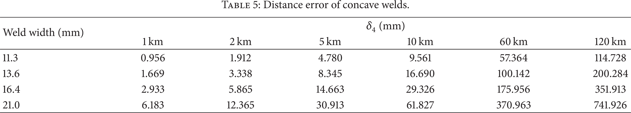
From Table 5, the following laws can be obtained. (1) When weld width is fixed, the distance error in 1 km is 1/2, 1/5, 1/10, 1/60, and 1/120 of the errors in 2 km, 5 km, 10 km, 60 km, and 120 km, respectively. (2) When pipe length is fixed, the distance error increases with the increase of weld width. (3) The distance error increases with the increase of the pipe length.
According to Tables 2, 3, 4, and 5, the above distance error is 49.701%, 49.786%, 0.485%, and 0.028% of the total error, respectively. The errors caused by difference between actual and nominal diameters and diameter difference among wheels are 99.487% of the total error. The error caused by concave weld is 0.056% of the first two errors, respectively.
6. Solutions
According to the accumulation characteristics of the positioning error, the following solutions for reduction of the position error are proposed.
(1) Calibration of Wheel Diameter. Before the defect detection, the wheel with diameter error can be judged and replaced during calibration.
(2) Detection in Sections. Magnetic marker, which is the infrastructure of pipeline construction, is set on the ground, above the pipeline. Each magnetic marker has its mileage datum on land. Thus, it can provide reference for positioning. Combined with the time the odometer wheel passes through the magnetic marker, the positioning error correction can be realized. In the practical detection process, for part of long-distance pipelines, the magnetic markers are placed every 2 km, where the accumulation error is in allowed range, to obtain pulse signal numbers. The optimum signal to minimize the gross error is selected for distance calculation. In this case, the accumulation error is replaced by relative error, resulting in high accuracy of position.
7. Conclusions
In this paper, the error factors of positioning in the internal pipeline defect detection are analyzed. The errors are classified into systematic error and random error. The mathematical models, the accumulation characteristics, the relationship of the errors, and the effect of them on total errors are investigated. The following conclusions are drawn.
The positioning error of odometer wheel consists of systematic error and random error. Systematic error includes difference between actual and nominal diameters, diameter difference among wheels, and terminal error. Random error includes initial point error, weld error, and oversized clearance.
Based on the mathematical models, the calculation examples, and the analysis of error characteristics, the fact that positioning error, except for terminal error, increases with the increase of the pipe length is obtained. The errors caused by difference between actual and nominal diameters and diameter difference among wheels are 99% of the total error.
The methods of diameter correction and detection in sections are proposed to improve the positioning accuracy.
In the detection, the further researches of the following problems are necessary.
The counting of odometer wheels is compared among sections for decision analysis. The further researches of this data fusion technology for positioning error decrease are needed.
In the detection, the error model of odometer wheel under the influence of multiple factors needs further study, due to the positioning result being affected by multiple factors.
Conflict of Interests
The authors declare that there is no conflict of interests regarding the publication of this paper.