
Abstract
With the rapid development of robot technology and its application, manipulators may face complex tasks and dynamic environments in the coming future, which leads to two challenges of control: multitasking and changing load. In this paper, a novel multicontroller strategy is presented to meet such challenges. The presented controller is composed of three parts: subcontrollers, inner-learning mechanism, and switching rules. Each subcontroller is designed with self-learning skills to fit the changing load under a special task. When a new task comes, switching rule reselects the most suitable subcontroller as the working controller to handle current task instead of the older one. Inner-learning mechanism makes the subcontrollers learn from the working controller when load changes so that the switching action causes smaller tracking error than the traditional switch controller. The results of the simulation experiments on two-degree manipulator show the proposed method effect.
1. Introduction
Manipulators, as one of the most popular robots in the world, are often used in industrial factories instead of millwright, welder, carrier, and other workers in product line to reduce costs and enhance quality. This pattern of manipulator utilization works well in the past several decades but is meeting and will meet great challenges [1] from the fast changing manufacturing orders because of the growing number of people who want their daily products different from others'. Besides industrial factories, more and more manipulators are used in the outdoor [2–5] or indoor [6, 7] environments individually or fixed on moving platforms. To fit these situations, the complexity of task and environment should be considered when we design the controller of manipulator.
Many researchers have focused on this issue. In [8, 9], a human collaborator in the manipulator's working space was considered and the integration of humans and robots behaviors was discussed. Paper [10] presented a novel control strategy for manipulator in unknown environments. Obstacle avoidance during manipulation tasks is studied in [11]. Paper [12] discussed the control problem of manipulator in random vibration. Paper [13] tried to resolve the problem of multitask allocation. The variable structure control (VSC) with sliding mode has been used to solve the load disturbance and other uncertainties [14]. Iterative learning controller of manipulator can help to finish repetitive tasks [15, 16]. Intelligent learning control method is becoming an effective strategy for manipulator with complex task and environment. In [17], neural networks are applied to control the manipulators to deal with the model uncertainties and the varying workload problems. Paper [18–20] used the fuzzy control and got good performances in certain circumstances. Obviously, it is very hard to use only one controller to reach the control goal for the manipulators may encounter different circumstances. Multicontroller approach is the typical case which has been widely used in complex systems [21]. The multicontroller approach has attracted many researchers in the robot control field during the last few decades due to its tolerance to system failure [22, 23], flexibility in linear parameter-varying applications [24], and success in kinetic modeling of logic-based systems [20]. Paper [25] used the multicontroller in Acrobot robot. Paper [26] used the architecture to control an ocean ship successfully. Sliding mode control is a typical method of multicontrollers and has been widely used in manipulator control [14, 27].
Although we can find many papers about this issue, we need to get down to some basic problems about manipulator control. First, what kind of factors should be considered at current time? Before we design complex controllers, the manipulator without any external sensors, so called the first generation manipulator that has only joint angle sensors, should be considered first. For this kind of manipulator, environment complexity often means changing loads. Obstacles, trajectories, and other factors should be considered later. The second problem is what kind of skills should be integrated into the controller. Because of the load changing, learning skill is necessary. And multicontroller strategy allows us to design controllers individually for each predefined situation. Based on such considerations, a multicontroller structure with multiple learning mechanisms is presented in this paper to deal with the control problem of manipulator with multitasking and changing load.
The remainder of this paper is organized as follows: the two main problems of controlling the manipulator are presented in Section 2. The control architecture based on the inner-learning mechanism is proposed in Section 3 and the stability is proved in Section 4. Numerical simulation studies are carried out on a two-link manipulator to verify the effectiveness of the controller in Section 5, followed by the conclusion in Section 6.
2. Problem Formulation
We consider a robot manipulator whose dynamic model is expressed in Cartesian space as follows:

where q,
D(q) is symmetric, bounded, and positive definite matrix.
G(q) is uniformly bounded; hence, ∥G(q)∥ ≤ c, where c is an unknown positive parameter.
For the above dynamic system, the problems of controlling it today include two aspects: (a) the manipulators should deal with multitasks when working; that is to say, they have to handle different works after being installed on workstations or other platforms. And (b) the manipulators should undertake different workloads when working; the workload may change under different situations. We will discuss the two problems in detail in the following.
2.1. Deal with Multitasks
The robot manipulators are assigned to various tasks for the growing number of people wants their daily life to be easier and more convenient than the traditional life. The manipulators may need to do some irregular works such as carve some different shapes or curves on the surface of some products; they may also need to do some repeated works like stowing or transporting things in the factory. Above all, manipulators have to finish different tasks to ease people's daily life today. These tasks are generally abstracted to different trajectories on theoretical analysis such as periodical curves, aperiodic curves, and other special trajectories. To simplify the analysis, we use the periodical and aperiodic trajectories as the research object in this paper. The trajectory of the manipulator is decided by the angle which is given by the tasks. So we can use Q d (t) to represent the tasks and describe the multitasking model by the following piecewise function:

where F(t) is a two-dimensional function that sets the target angle for the joints. Equation (2) is a piecewise functions, and we can set different angles by defining different F(t). As in Figure 1, the manipulator may track aperiodic trajectory to finish task 1 before time t1 and track periodic trajectory to finish task 2 after time t1.

The trajectories of two different tasks.
2.2. Undertake Changing Load
To achieve different targets, the manipulators have to undertake various workloads; they may face the following situations: (a) the workload is a constant in one task but changes to another constant when doing another task; (b) the workload is a constant but changes with different operation objects in one task; (c) the workload may change over time; (d) the workload may face the mixture of the above various situations. The changing pattern of the workload also has two cases: time-driven and event-driven. Obviously, it is a great challenge for us to design a controller to handle all the above situations. So we considered the situations (a), (b), and the time-driven cases in this paper to simplify the theoretical analysis; the physical model can be described by the following piecewise function:

where pl is the workload of the robot manipulator, c i (i = 1, 2,…, n) is a positive constant, and t is the duration time of c i .
As in Figure 2, we can see that the load will make a change when it comes to the changing time and lasts for a period until the next change time comes. The time of the load change may be the time of the task change like situation (a) or in the process of performing one task like situation (b). The changes may happen simultaneously or one after another, so the controller may lead to large errors if it is unable to adapt to the changes quickly.

Schematic of the changing load. l1, l2, l3…l n is the load constant. t1, t2, t3 is the change point when the load changes from one constant to another.
3. Control Scheme Based on the Inner-Learning Mechanism
This paper will solve the aforementioned two problems which may occur during the working of the manipulator. We can use multicontroller architecture to solve the problems, but, as mentioned earlier, merely using switching control cannot guarantee the good effectiveness of the control system because the subcontrollers are unable to acquire the task or workload change information from each other when the control system switches from one controller to another. But it could be solved if the subcontrollers have the ability to learn the information of environmental changes and learn the information of the working controller when switching. So, we introduce the mechanism which we call the inner-learning mechanism; it can make the controllers learn the system change information from each other and adjust their parameters by the knowledge they learned. Based on this mechanism, we propose a control scheme which addresses the following issues. (1) It can reselect the most suitable subcontroller as working controller to handle current situation instead of the older one; (2) the controllers can learn the system information such as load change from the working controller and cause smaller tracking error when switching under the guidance of the inner-learning mechanism. Considering these, we can get an overview of the architecture from Figure 3.

Multicontroller architecture based on inner-learning mechanism, where C n is the subcontroller and G is the control plant.
As in Figure 3, the core part of the control structure is surrounded by the dashed line; it is similar to a polygon rotating structure and contains three main aspects: (a) subcontroller; (b) switching rules; and (c) inner-learning mechanism. They are to be introduced in the following sections.
3.1. Subcontrollers
Our goal is to design a multicontroller C to stabilize the manipulator. The multicontroller C consists of a family of subcontrollers {C m }m = 1 n and is associated with a switching signal, where each subcontroller C n belongs to the constrained set and the switching signal indicates the next working controller within the family {C m }m = 1 n [28].
The precondition of the existence of the inner-learning mechanism is that each subcontroller has the learning skill. That is to say, when we choose subcontrollers, we should make sure they can learn the information of the changes from the working control and adjust their parameters to the best. Under the guidance of these principles and for simplicity, we choose the PID controller and iterative learning controller (ILC) as the two subcontrollers.
PID controller has been widely used in industrial robotics for the feature of simple structure and easy realization. Consider the feature of nonlinear and varying load of the robotic system; we use neural network adaptive PID controller as method 1. Since the robots often need to track the periodic curves and the iterative learning control has a good effect for the cyclical action, so we choose the ILC controller as method 2.
When we design controllers, we always try to make the controller as simple as possible under the premise that does not affect system performance. PD and PID controllers are used very frequently in industrial robot control. Practice has proved that PD control is more effective than PID control and it has a simpler structure. Actually, PD controller is one kind of PID controller whose parameter of the integral term is zero, so the controllers are all chosen PD-type in this paper. To simplify the description, we use C1 and C2 and subsystem 1 and subsystem 2 to represent method 1, method 2, and the corresponding two subsystems, respectively. The RBF neural network has a good approximation ability; we can use it to adjust the parameters; reference [29] has described this method in detail. The adaptive PID controller can be written as the following equation:

where kp0, kd0 will be adjusted by the neural network.
Controller C2 uses the open-loop learning algorithm; the algorithm can be defined as
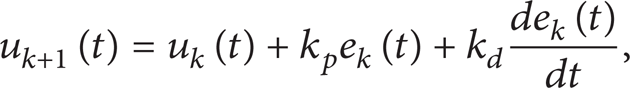
where the subscript k = (0, 1,…, n) is the index of iterations, u k (t) is the former control, and k p e k (t) + k d (de k (t)/dt) is a correction term of the former output error. The convergence of the algorithm should be considered when we use the ILC controller.
3.2. Switching Rules
The switching rules should guide the switching of the subcontrollers with the change of tasks and make a decision about which controller to switch to. The switching rules can be defined as

where t0 denotes the initial time of the system and x, y represent the states of input and output, respectively. We assume that m ∈ {1, 2,…, n}, and the candidate controller will switch to C m when σ(t) = m. The rules can be designed as time-driven, state-driven, or event-driven patterns; we should design the switching rules according to the actual situation. For the robot manipulator, it will spend a fixed time to complete the specific task and switch from one to another when the task and load change. So we can design a time-driven switching law to organize the switching of the subcontrollers. The rules can be defined as follows:

where the switching signal σ only depends on the time and its past values. That is to say, the switching will happen when a task is completed.
3.3. Inner-Learning Mechanism
The innovation of the new architecture is the introduction of inner-learning mechanism. In Figure 3, the subcontrollers are interconnected by the learning mechanism; it can guide the mutual learning of the subcontrollers so that the current controller can get the information from the working controller and adapt to the environment quickly. The design of the mechanism is various from different subcontrollers for its different self-learning mechanism, so we should design an appropriate learning mechanism to realize the inner-learning between the subcontrollers. Consider the two subcontrollers we chose: controller C1 can adjust the parameters to the best if the initial value failed to meet the requirements of the control action; controller C2 can achieve the best control effect through continuous learning. They all have the ability of self-learning, so we designed the following learning mechanism.
Before switching, C1 adjusts the value of k p and k d to a group of optimal parameters k p d and k d d which will be transferred to the iterative learning controller. Then, the control will be switched to

After switching, (8) will be the active controller. The new candidate can learn information from the two parameters k p d and k d d which are carrying the information of subsystem 1; this would help the candidate controller adapt to the changes of the load of task, reduce the overshoot, and exert effective control.
By periodic revision of the control signals, controller C2 can achieve the best control effect after running some times. Before the candidate switched to C1, the system should store the last control input u
d
(t) which is also the optimal control of C2. The initial control effect of C1 controller is determined by the parameters

where e and
4. The Stability of the System
Before discussing the stability, we need to make the following reasonable assumptions and definition [29].
Assumption 1. The trajectories and their first and second order derivatives are bounded.
Assumption 2. The states of the manipulator are measureable and observable.
Assumption 3. For each iteration, the initial conditions are satisfied; q
d
(0) = q
j
(0),
Remark 4. For a real robotic system, its joint angle, angular velocity, and angular acceleration must be bounded, and these states can be easily measured by the sensors, so we can ensure the rationality of Assumptions 1 and 2. Assumption 3 is typical in the literature of iterative learning control, and it can be ensured in a real system. So we can see that the 3 assumptions are reasonable.
Definition 5. We called the positive value τ a the average dwell time under the switching rule σ if it satisfies the following conditions:

where T > t ≥ 0 represent the running time of the system, Nσ(t, T) is the switching times on interval (t, T), and N0 is a positive number.
In order to describe the stability of the system, we defined V as the potential energy of the manipulator and get the following theorem.
Proof (a) The Stability of the Subsystems. For subsystem 1, [30] has given a detailed proof of its stability. It used Hamilton function as the Lyapunov function and got the conclusion that if the control gain K p satisfies (11), then the system is stable. Consider
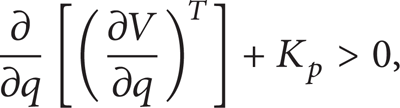
where K p is the error gain matrix of the PD algorithm in [30].
From the properties of the robot dynamics, we have

In our method, kp0 corresponds to K p in (11); we can see that if kp0 in subsystem 1 satisfied (11), then we can prove the stability of subsystem 1. So we substitute kp0 into (11) and get (∂/∂q)[G T (q)] + kp0, where G(q) is the gravity term in (1) and is obtained by (18) in our robotic system and kp0 is obtained by (9), for u d (t) has been able to stabilize the system, so the least squares method can make the parameter kp0 meet the following inequality:
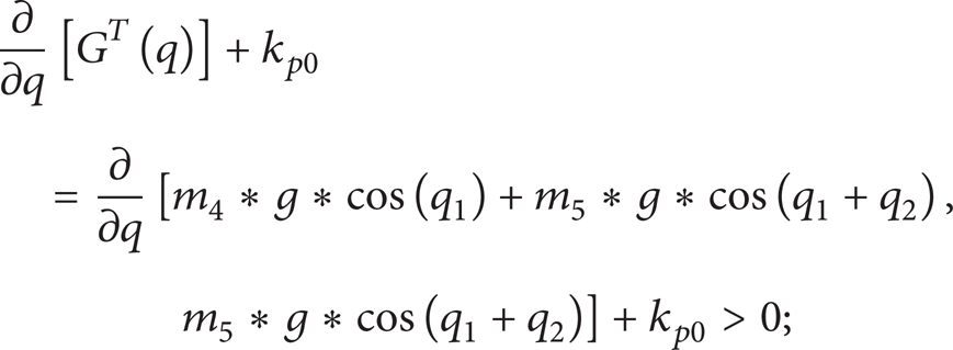
the detailed calculation process will be omitted here. For a real robotic system, it is easy to verify the establishment of (13) and from [30] we can get the result that subsystem 1 is stable.
For subsystem 2, we will simplify some symbols before the stability proof. Consider

where λ
min
(·) represents the minimum eigenvalue of the matrix and

where K d 0 is the initial control gain and Λ is a diagonal positive definite matrix, then the system subsystem 2 is stable, for t ∈ [t s , t f ] (where t s , t f are the start time and finish time of the iteration, respectively).
Reference [16] has proved that Lemma 1 is established for the variable gain. K d 0 in (15) is corresponding to K d d of subsystem 2. So subsystem 2 is stable if K d d satisfied (15). The inner-learning mechanism can make the optimal control of subsystem 1 the initial control of subsystem 2. So (15) is established when the system switches to subsystem 2 and the stability of subsystem 2 is obtained.
(b) The Stability of the Switching System. The control architecture we proposed is a multicontroller switching system; we should note that the stability of subsystems is not equal to the stability of the switching system [31]. So we should demonstrate the stability of the switching system.
Paper [32] proposed a stability analysis method based on the average dwell time which is defined in Definition 5. Indeed, if the switching system stays on each subsystem long enough to ensure that the energy reduction is equal or more than the energy increase caused by the switching, then the stability is guaranteed. It has been proved that if the dwell time τ a is sufficiently large, then the proposed switching system is stable [33]. Its physical meaning is that the system is stable if there is sufficient time to offset the energy increasing trend caused by the switching. So, if the time to finish each task is long enough for the manipulator, then the system is stable.
5. Simulation Results
In order to verify the effectiveness of the controller, we designed the following simulation.
The manipulator used for simulation is a two-revolute joint robot, as shown in Figure 4.

A two-revolute joint robot.
Due to the limitation input method, we rephrase it here, that is: The simulation experiments use the model which is described in (1). D(q),
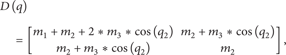


where m i in (2) is the element of the vector M which is given by

where p
l
denotes the workload, P is the parameter vector of the robot which can be described as
Group a. Consider
Group b. Consider

The changing mission trajectory can be defined as the changing curve at time t1. Also, the load change can be defined as

It means the load will change at time t1′.
Target trajectory and task load changes can be divided into the following cases.
Case 1. t1 = t1′; namely, the changes occur at the same time.
Case 2. t1 < t1′; namely, the load changes after the change of target trajectory.
Case 3. t1 > t1′; namely, the target trajectory will change after the load.
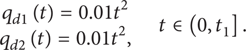
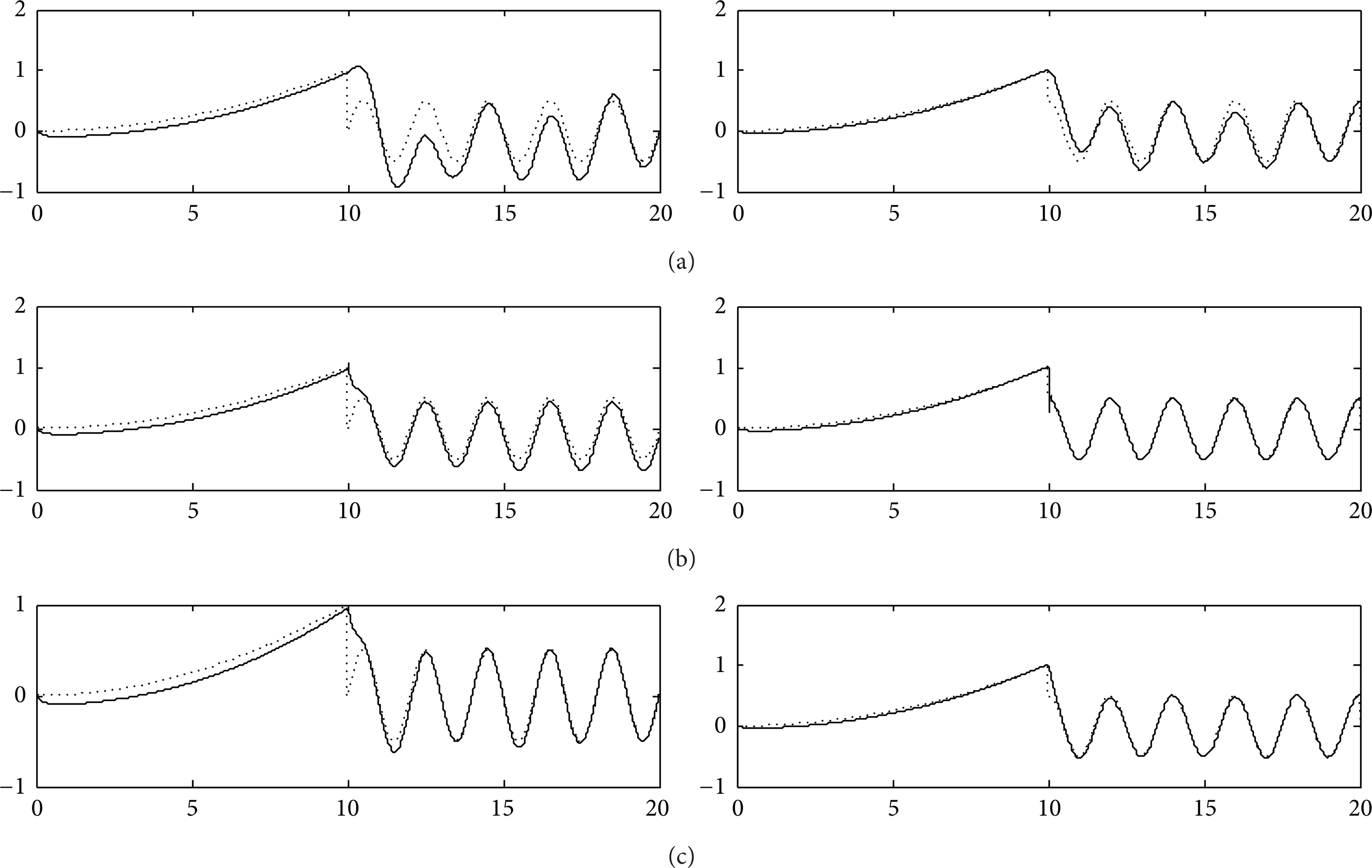
In the experiment, we set t1 = t1′ = 10 in Case 1; t1 = 10, t1′ = 15 in Case 2; t1 = 10, t1′ = 5 for Case 3. Then, we use adaptive PID controller and switch controller based on PID controller, iterative learning controller, and the proposed controller to control the double-joint robot, respectively. The simulation results are shown in Figures 5, 6, 7, 8, 9, and 10.

Control effects of Case 1. (a), (b), and (c) show the effects of switching control without inner-learning mechanism, adaptive PID control, and inner-learning switching control, respectively.

Tracking errors of Case 1. (a), (b), and (c) show the trajectory tracking error of the switching control without inner-learning mechanism, adaptive PID control, and inner-learning switching control, respectively.
Control effects of Case 2. (a), (b), and (c) show the effects of switching control without inner-learning mechanism, adaptive PID control, and inner-learning switching control, respectively.

Tracking errors of Case 2. (a), (b), and (c) show the trajectory tracking error of the switching control without inner-learning mechanism, adaptive PID control, and inner-learning switching control, respectively.

Control effects of Case 3. (a), (b), and (c) show the effects of switching control without inner-learning mechanism, adaptive PID control, and inner-learning switching control, respectively.
Tracking errors of Case 3. (a), (b), and (c) show the trajectory tracking error of the switching control without inner-learning mechanism, adaptive PID control, and inner-learning switching control, respectively.
From the above simulation result, we can see that the control architecture we proposed is more suitable for the complex robotic system; it can make the robot more adaptable to the complex environment and solve the problems we proposed in the beginning of the paper effectively. To see the effectiveness of the architecture more clearly, we calculated the summation of the trajectory tracking error mean of the three different control structures in three cases and made Table 1.
The error mean comparison of the three controllers (where

From Table 1, we can see that the control architecture we proposed has a better performance than the two common methods.
6. Conclusion
In this paper, we discuss the control problems of the manipulators with changing load and multitasks and propose a novel kind of multicontroller architecture for the robot manipulator system and demonstrate the stability of the architecture. The new architecture can establish an internal learning mechanism for the multicontroller, guarantee the continuity of the system, and avoid the impact of the transient response caused by the switching action. The result of the experiment shows the effectiveness of the proposed architecture. Our future work will focus on the applications of this novel method in multielectromechanical and embedded systems.
Conflict of Interests
The authors declare that there is no conflict of interests regarding the publication of this paper.
Footnotes
Acknowledgments
This work was supported by the Chinese Fundamental Research Funds for the Central Universities (nos. CDJZR11170006 and CDJZR12170018), the National Natural Science Foundation of China (no. 60905053), and the Chongqing Natural Science Foundation (no. 2011BB0081).