
Abstract
Considering the issues of lower limb rehabilitation robots with single control strategies and poor training types, a training method for improving muscle strength was put forward in this paper. Patients’ muscle strength could be achieved by targeted exercises at the end of rehabilitation. This approach could be realized through programming wires’ force. On the one hand, each wires force was measured by tension sensor and force closed loop control was established to control the value of wires’ force which was acted on trainees. On the other hand, the direction of output force was changed by detecting the trainees’ state of motion and the way of putting load to patient was achieved. Finally, the target of enhancing patients’ muscle strength was realized. Dynamic model was built by means of mechanism and training types of robots. Force closed loop control strategy was established based on training pattern. In view of the characteristics of the redundance and economy of wire control, the process for simple wire's load changes was discussed. In order to confirm the characteristics of robot control system, the controller was simulated in Matlab/Simulink. It was verified that command signal could be traced by control system availably and the load during muscle training would be provided effectively.
1. Introduction
Trauma and illness result in malformation for human body that trigger different levels of dyskinesia. It seriously affects the quality of people's life. Data show that effective rehabilitation result would be acquired through combining modern medical procedures with kinesitherapy [1].
In recent years, it has been accepted that rehabilitation training with the help of robots has replaced traditional physical exercise therapy [2, 3]. However, rehabilitation training mainly depends on robots with accurate control strategy. Scholars have developed some researches aiming at control system of rehabilitation robots. An upper rehabilitation robot (Arm Guide) with two degrees was proposed by Toshiro Noritsugu who used an impedance control strategy with inner position loop and outer force loop to control robot. But force limitation was not set, which resulted in compliance when interaction force was produced. That was not satisfied with the requirements of passive rehabilitation training [4]. For the sake of satisfying patients’ aspiration that robot follows their autokinetic movement, a control strategy with outer position loop and inner force loop was used in Lokomat (which was developed by Jezernik and Riener). The strategy would make position error as reference force through impedance conversion [5]. However, the ideal reference trajectory would not completely correspond with human autokinetic movement, so it needs further improvement. Zhang Lixun and Liu Pan presented a concurrent control strategy of force and position when they studied wire-driven parallel robot with 3 degrees of freedom. The control strategy employed the idea which controlled force and position separately. Force loop was used in controlling wires’ tension and position loop was applied in tracing the trajectory of moving platform [6]. It could be realized easily; however, the validity requires further verification. In [7, 8], a rehabilitation robot was proposed which was used to improve patients’ muscle strength. It adopted the control strategy with outer position loop and inner force loop. During the process of robot control, trainees’ movement was in accordance with reference trajectory of robot. This control strategy did not obtain better effect than traditional training method for improving patients’ muscle strength. Considering the expected muscle strength training is that people make autokinetic movement and robot acts resistance on them according to their movement.
The prime purpose of this training pattern of muscle strength in this paper is to further enhance patients’ muscle force by exerting external force for those who have normal gait but not enough muscle strength.
2. Rehabilitation Robot Model of Lower Limb with Extension and Flexion
2.1. The Composition and Operating Principle of Man-Machine Collaboration System
The system of lower limb rehabilitation robot with extension and flexion is shown in Figure 1. Patient and robot constitute a man-machine collaboration system with binding effect [9]. This robot presents a bilateral symmetry and each side is formed by three driving wires. The knot as high as patient's ankle joint is linked by the ends of three wires, which are connected to a thin plate bound with patient's crus. The other end (B1) of wire 1 around wheel fixed on screw-nut mechanism is connected with torque motor 1, and tension sensors on wheel are used to measure wire's tension. The other ends (B2 and B3) of wire 2 and wire 3 around wheel fixed on frame are linked to torque motor 2 and torque motor 3, respectively. During rehabilitation training, patient is pulled by treadmill and wires’ knot of lower limb rehabilitation robot to realize the man-machine interaction and complete various training schedules.

Lower limb rehabilitation robot.
2.2. The Planning of Wire Traction
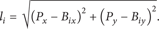
As is shown in Figure 2, world coordinate system was built according to original point O. One end of wires l1, l2, l3 acted on knot p located in ankle joint collectively and generated loading force F by all wires’ traction on p. The overall thinking of wire traction planning is that after expected loading force F was programmed, angle matrix A(η) would be solved by angles α, β, λ between wires 1, 2, 3, and plumb line. In terms of the relationship of equilibrium, A(η)T = F, the tension vector,

Structure diagram of wire driving cellblock.
In order to increase the efficiency of loading force and decrease the stress that external force acts on knee joint [10], the vector of loading force F is perpendicular to crus all the time, namely, ϕ3 = 90°, and its value is determined by specific muscle strength of trainees.
Based on the law of angle changes of hip joint θ1 and keen joint θ2 in CGA database, it can be approximated as follows [11]:

According to robotics, the location of knot p can be deduced as

So the length of wires is described as
Wires’ velocity can be achieved by making derivation to (3)
In the process of motion control, wire 1 bisects the angle between wire 2 and wire 3 by planning the location of rigid chain, namely, ∠B1PB2 = ∠B1PB3. By means of geometrical relationship, the position of the sliding block is attained as

According to angular dependence and force balance equation, we can obtain the equation as follows [12, 13]:

where α = ac sin((P x − x1)/l1), β = ac sin(P x /l2), γ = ac sin((xB3 − P x )/l3).
A(η) and b should be defined as

We can deduced that

Therefore, we can turn coupled problem of driving force among three wires into solving issues of nonhomogeneous equation set. Apparently, (8) has an infinite number of solutions. Ambiguity is not allowed in control system; hereon, we can attain the solution of systematic wire traction by setting the tensile force of wire 1 and keeping it tense in the process of traction.
3. The Control Strategy of Lower Limb Rehabilitation Robots in Muscle Force Training Pattern
According to the requirements of patients in different rehabilitation stages, rehabilitation training method can be divided into passive training and active exercise. An approach based on outer force loop in [14] has been successfully applied in the fields of robotic control with force tracking. In this paper, we adopted torque motors as driven units which was employed in closed loop control with force planning. Passive and active training can be realized through acting force on trainees and controlling the value of wires’ force. The control principle diagram is shown in Figure 3.

Control diagram of muscle training pattern.
In Figure 3, because of the included angle α between wire 1 and because plumb line was affected by the position (X4) of screw-nut mechanism, therefore, the dynamic model of robot system was influenced too.
The fundamental is that robot control system receives location information of wires from optical-electricity encoder, and planning force of wires is acquired as the set value of closed loop force control by force controller. The resultant force of three wires serves as control target which acts on the knot of ankle joint. The accuracy of robot's output force depends on not only the force controller, but the measuring accuracy of wires'position.
4. Modeling of Wire Unit
The dynamic characteristics of three wires are uniform when lower limb rehabilitation robot locates in certain position. On the basis of Figure 2, we can build the dynamical model with damping-spring of single wire [15, 16]. As Figure 4 shows, k is wire's equivalent stiffness; J e and J m are rotational inertia of tension sensors and motors; r e and r m are wheel radius of sensors and motors; x i and x0 are positions of the ends of traction and drive of wires; B m is viscous friction coefficient; θ mi is rotation angle of motors; T mi is torque of motors.

Dynamic model of wire's drive unit.
According to the voltage equations of motor-armature and torque equilibrium equation, we can obtain the output-transfer function of torque of motors, which is given as

where U is output voltage of motors, C m is torque constant of continuous current motor, C e is back electromotive force constant, L is inductance of motor-armature, and R is loop resistance of armature.
The equilibrium equation of tension sensor units can be described as

where V i is running speed of the traction end of wires.
Substituting (9) into (10), the kinematic equation of flexible drive unit can be written as.
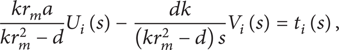
where a = C m /(Ls + R), b = C m C e s/(Ls + R), c = J m s2 + B m s, and d = b + c + J e s2(r m 2/r e 2).
5. System Simulation
We need to make simulation to man-machine model in order to verify planner and controller and inspect control effectiveness of lower limb rehabilitation robot in training model. According to Figure 2 of robot's configuration and torque motor of robot, we set the parameters of robot system as follows: B2 = (0,0.72) m, B3 = (1.69,0.72) m, r e = 0.015 m, r m = 0.06 m, B m = 0.0178 N·m·s/rad, k = 2 × 10⁶ N/m, J e = 6.237 × 10⁻⁶ kg·m2, J m = 1.4 × 10⁻² kg·m2, C m = 1.875 N·m/A, L = 0.0033 H, R = 3 Ω.
5.1. Setting the Driven Value of Wire 1
For the sake of researching the relationship between target acting force and driving force of flexible drive unit in the process of rehabilitation training, planning model (represented in Section 2.2) is built in Matlab [17]. On the one hand, when we assume the value of wire 1 is 40 N, that is, t1 = 40 N, and then change target acting force, the changing law of the tension of wire 2 and wire 3 is achieved and shown in Figure 5. On the other hand, when we give the value of target acting force, that is, F = 40 N, and then change the value of wire 1, the changing law of the tension of wire 2 and wire 3 is obtained and shown in Figure 6.
Dynamic curve of target acting force influencing the planning force of wires.

Dynamic curve of driving force of wire 1 acting on other wires.
5.2. Simulation of Force Planning
Based on the dynamic model of wire driving units, we can accomplish the simulation and analysis of system's force planning with the help of establishing the model of control system in Matlab/Simulink by assuming the acting force is 40 N (F = 40 N) and constant driving force of wire 1 is 74 N (t1 = 74 N). Meanwhile, we set the movement trainees’ motion in step with the movement of (1). It means that the active movement locus of driving knot is in line with Figure 7. Planning driving force and output driving force of wire 2 and wire 3 are shown in Figure 8. Planning value and realistic value of acting force are shown in Figure 9.

The trajectory of knot planning.

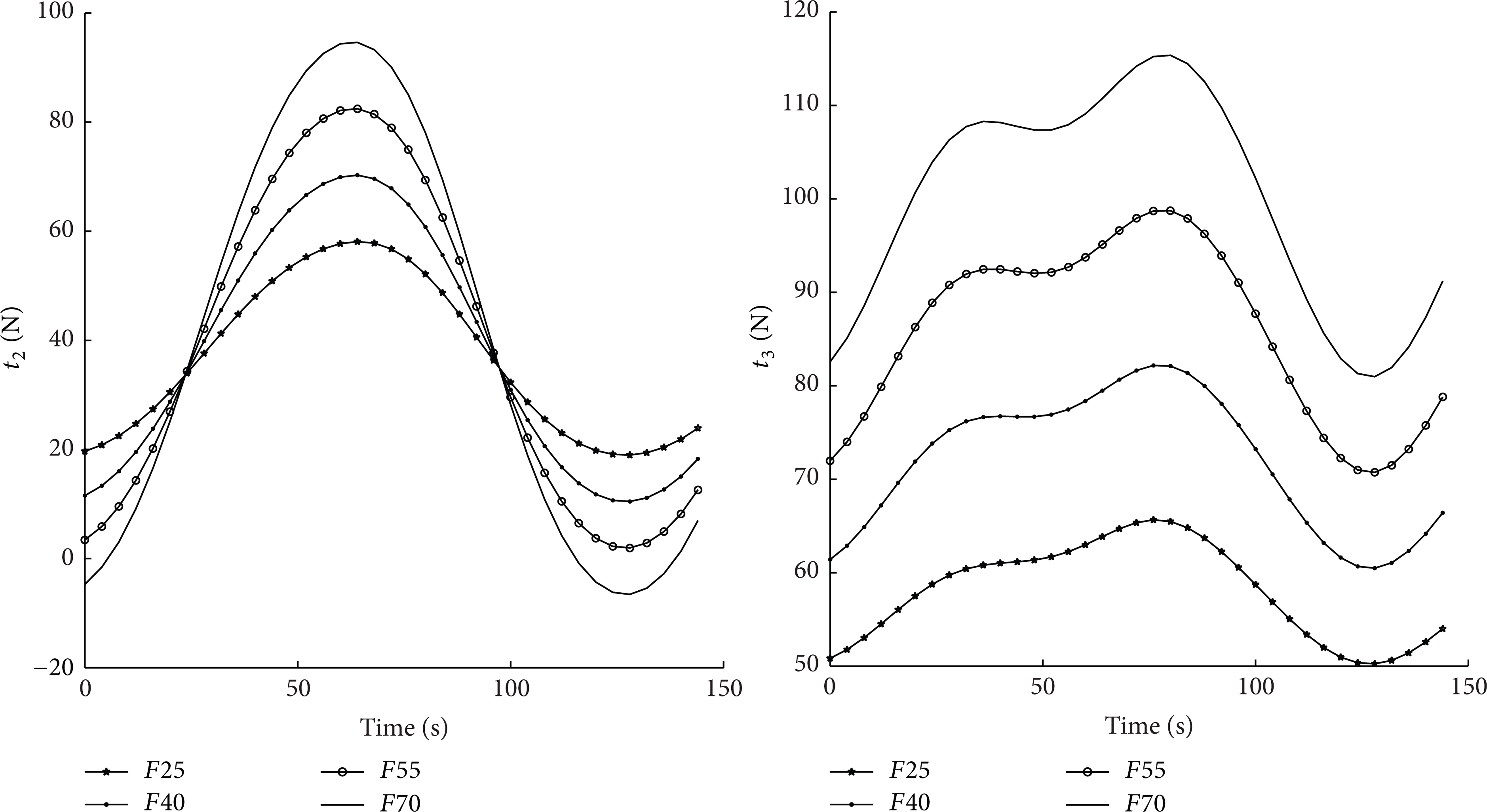
Dynamic tracking curve of wires’ driving force.
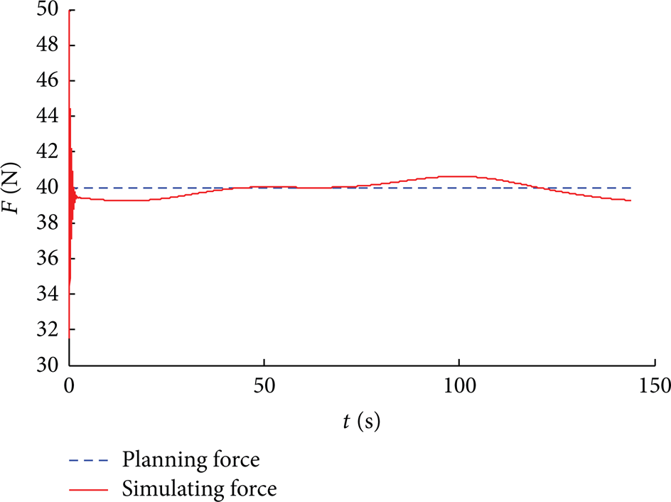
Acting force tracking curve.
6. Result and Discussion
It is observed that the amplitude of driven force of wire 2 largens with the enlargement of expected acting force and driven force of wire 3 has wholly enhancement in Figure 5. Motion position of knot would influence the driven force of wire 2 and wire 3 during training. When the value of expected acting force is 60 N (F = 60 N), the tension of wire 2 appears negative, which is not allowed by one way load carrying characteristic of wires. Therefore the setting value of wire 1, namely, t1 = 40 N, is too small. In order to satisfy the requirement of one way load carrying characteristic, it should be increased. During realistic wires’ force control, to enhance the reliability, unidirectional load carrying characteristic should be satised, namely the pretightening force of wires would be greater than minimal traction force. In Figure 6 the driving force of wire 2 and wire 3 entirely largens with the increase of that of wire 1. The enhancement of wires’ force is employed in balancing inner force. It is the part of null space of wires’ tension solution. According to the request of control policy of lower limb rehabilitation robot, acting force F is set by patients. When F is fixed, the larger the driving force t1 of wire 1 is, the higher the reliability that satisfies mechanical characteristics of wires would be, and the more enhanced the static rigidity of system and the worse the system flexibility would be. Considering the safety of rehabilitation robot, if wires’ torque becomes larger, the potential danger would be more serious. Hence, the value of driving force of wire 1 should be set in view of the value of acting force and the control requirement of realistic flexibility.
In Figure 7, traction knot moves from low point to high point of planning trajectory anticlockwise. At this moment, driving force and knot motion of wire 2 have the same motor direction, so motor 2 works in power-driven state and the loss of movement is afforded by itself. Because of the influence of velocity jamming (V i in (11)), driving force appears hysteresis. However, driving force and knot motion of wire 3 are in opposite motor directions; therefore motor 3 works in breaking model and the loss of movement is undertaken by other motors. On account of the influence of velocity jamming, driving force presents advanced phenomenon in Figure 8. When the original moving state is transformed, the driving force of wire 2 presents advanced phenomenon, and wire 3 appears hysteresis. Therefore the original state of traction knot determines the phase of output driving force of wires. It is obvious that output acting force is less than expected acting force in the first half cycle. It is obvious that output acting force is less than expected acting force in the first half cycle. Which is the opposite in the second half cycle. It also reflects the influence that the original state of knot motion acts on the output of acting force, and the maximum error is about 3%, which can be accepted by rehabilitation training and thus verify the model of control system.
7. Conclusion
This paper mainly aims at the problems of insufficient muscle strength for the patients with body injury in later period of rehabilitation. A training method of muscle strength based on closed-force loop is suggested according to the construction of lower limb rehabilitation robot and training pattern. Considering the characteristics of redundancy of wire driving system and unidirectional load of wires, we make the argument and analysis to the relationship between output acting force of robot and wires’ tension. On the basis of fixed motion planning of rigid chain and mechanical relationship of flexible drive unit, dynamic model that makes driving velocity of wires as disturbance of force control is established. Matlab/simulink is used to build a simulation model by which the impact of wire 1's driving force and the given value of expected acting force on the driving force of wire 2&3 is analyzed. The impact of wire 2 and 3's driving force and acting force during active training is also analyzed. Simulating the effect of driving force of wire 2 and wire 3 on knot during active training. The phase influence of original moving state of knot on driving force of wire 2 and wire 3 is achieved and the maximum error is about 3%. It indicates the validity of force planning of lower limb rehabilitation robot. The tracing performance of force control of simple wire has met the request of rehabilitation training. It would lay theoretical foundation for the construction of robot control system and later experiments.
Conflict of Interests
The authors declare that there is no conflict of interests regarding the publishing of this paper.
Footnotes
Acknowledgments
This project is supported by National Natural Science Foundation of China (51405095); Technological Innovation Talent Special Fund of Harbin (2014RFQXJ037); Fundamental Research Funds for the Central Universities (HEUCF140709).