
Abstract
Ride quality became a very important factor in the performance of railway vehicles according to the expansion of high-speed railways and speedup of velocity of railway vehicles. In this study, the results of applying the MR (magnetorheological) lateral damper on the secondary suspension to reduce the vibration of the car body, directly relating to the ride quality of railway vehicles, were mentioned. In order to verify the control performance of MR dampers, a 1/5 scaled railway vehicle model was constructed, and numerical simulation and experimental tests were conducted. The MR damper for the experimental tests was produced and was attached between the car body and bogie of a full scaled vehicle, and a vibration controlling test was performed to improve ride quality on a roller rig. The skyhook control algorithm was used as the controlling technique, and regarding the test results, the RMS (root mean square) value was found by compensating the frequency of the lateral vibration based on the UIC 513 R Standard about the ride quality of railway vehicles. As a result of the test, it could be confirmed that vibration was reduced by approximately 24% when attaching the MR damper between the bogie and the car body compared to when applying a passive damper.
1. Introduction
The vibration of railway vehicles not only reduces ride quality by direct application to passengers, but also affects running stability. In general, previous passive suspensions composed of a spring and damper shows limits in simultaneously satisfying the objective of ride quality and running stability. Thus, the design perspective of previous passive suspensions was to compromise the two performance objectives in conformance to various running conditions. However, along with the speed increase of railway vehicles globally, procurement of running stability and ride quality became an important task; thus, technology development applying semiactive and active suspension is being actively researched in various fields. [1–3] Research on semiactive and active suspensions of railway vehicles is not easy due to the difficulty of increased testing time and production cost for applying various technologies or new mechanisms, due to the large sized experiment equipment and vehicles compared to automobiles. In addition, because railway vehicles have the unique characteristics by which the railway wheels make rolling contact on the rail, breaking down of the controller or suspension elements such as semiactive dampers or active actuators used in semiactive and active suspensions applied to railway vehicles can lead to a catastrophic accident. Regarding the suspension of railway vehicles, unlike the active suspension researched in various mechanisms such as oil pressure type, gas pressure type, and electromagnetic type, the semiactive suspensions were mostly researched and developed in the form of oil pressure type dampers, in which the variable orifices and solenoid valves are combined. [4, 5] Semiactive suspension using oil pressure type solenoid valves can create sufficient power; thus, it is suitable for railway vehicles. However, semiactive dampers using oil pressure solenoid valves require a separate oil pressure tank to supply fluid based on their characteristics and have repair and maintenance problems due to oil leakage. The recently researched semiactive suspension includes devices controlling the damping force by granting adequate voltage or current signals to the damper produced by using smart materials, such as electrorheological (ER) or magnetorheological (MR) fluids. Semiactive suspension using MR dampers have a comparatively simple system and easy repair and maintenance system compared to the previous semiactive suspension [6]. Sun et al. [7] performed tests on a roller rig and interpreted numerical values of the researches on the sensitivity of critical speed by applying the MR damper on railway vehicles. Lau and Liao [8] performed performance tests on the unit component by designing and developing MR dampers for railway vehicles. They performed a semiactive control simulation by applying the result on the numerical simulation model, and the on-off control technique was used, showing a result of a maximum of 38.9% reduction of the vibration of car body. Experimental researches based on field tests for researches applying MR dampers for railway vehicles are not being conducted and most of them are limited to numerical researches; therefore, there are limits in proving the validity of control performance. Therefore, many countries are currently undergoing research to adopt the suspension of automobiles and railway vehicles [8–10]. In particular, the MR damper for automobiles is being actively studied by theoretical and experimental method. Miao performed performance test on the controller of MR damper by theoretical and experimental methods [11, 12].
In this research, it was conducted to reduce the lateral vibration of the car body with simple skyhook control by attaching the MR damper laterally, an element of semiactive suspension, which has not been introduced in railway vehicles yet. As such, this research figured out the dynamic characteristics by numerical analysis with mathematical model of railway vehicles. Then, an MR damper was attached on a full scaled railway vehicle, and the validity of the control performance was sought to be verified through a running test.
2. Ride Quality and Vibration Characteristics of Railway Vehicle
In order to examine the dynamic characteristics and ride quality level of railway vehicles, a ride quality measuring test was performed on intermediate speed vehicles of 200 km/h and EMU (electrical multiple unit) of 110 km/h operating within the city area, as can be seen in Figure 1, before applying semiactive suspension to railway vehicles. The ride quality evaluation was performed based on the UIC 513 R “Guidelines for evaluating passenger comfort in relation to vibration in railway vehicles” standards. The vibration acceleration signal of a car body experienced by a human body was converted into a ride quality level (dB) by applying the sensitivity weighting curve. Regarding the horizontal vibration acceleration signal, the ride quality sensitivity weighting filter W d was applied, and the sensitivity weighting filter W b was applied for vertical direction vibration acceleration signals.
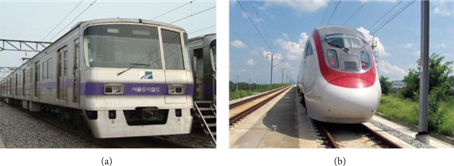
Rolling-stock to measure ride quality.
Figures 2 and 3 show the test results on ride quality regarding intermediate speed vehicles and EMU. Figure 2 shows the horizontal ride quality for EMU, exhibiting ride quality with an average value of approximately 102.2 dB, maximum value of 108 dB, and minimum value of 95.7 dB. Figure 3 shows the ride quality of intermediate speed railway vehicles, having an average value of 101 dB, maximum value of 106.9 dB, and minimum value of 92.9 dB. From the measurement results, the ride quality of railway vehicle shows a huge deviation between the maximum and minimum values, regardless of the vehicle type. This can be seen as an effect according to the suspension characteristics and structure, shape and maintenance condition of tracks, and running velocity of the railway vehicle. When viewed from the perspective of the operator of railway vehicles, there is a need to manage ride quality in a relatively consistent level, to provide comfortable passenger service, and to try to reduce the ride quality level. To do so, repairs and maintenance on vehicles and tracks are necessary; however, there are limits in improving ride quality without development of vehicles with outstanding ride quality. Thus, many countries are actively conducting research on active and semiactive suspension systems as a measure to prevent the increase of repair and maintenance costs of tracks and reduction of ride quality for the sake of speedup.

Test result on ride quality of EMU.

Test result on ride quality of intermediate speed rolling-stock.
3. Verification of Semiactive Suspension Performance Using a 1/5 Scaled Model
3.1. Semiactive Suspension of Railway Vehicles Applying MR Damper
The semiactive suspensions applied in current railway vehicles are mostly devices in variable orifice forms using oil pressure. The MR damper is a method that does not require mechanical valves that change the orifice gap of variable dampers. Such semiactive suspension using MR dampers have the advantage of requiring simple designing compared to oil pressure type semiactive suspension, being less complicated compared to active suspension, and not requiring as much external currents. The 1/5 scaled MR damper as Figure 4 to apply the MR damper for railway vehicles was designed and produced. Before the vibration control test of the MR damper on the 1/5 scaled roller rig, a performance test was performed on the unit component, and the relationship between damping force and the input current of MR damper was found as shown in Figure 5. The relationship of interpolation line can be represented by (1). The vel represents relative velocity between car body and bogie and imr is input current (A) for MR damper. Such estimation result was applied to the controller, to perform numerical simulation and experimental test.
MR damper for 1/5 scaled railway vehicle.

Test result of MR damper and approximate formula.
Consider

3.2. Verification of Control Function of MR Damper Using a 1/5 Scaled Railway Vehicle
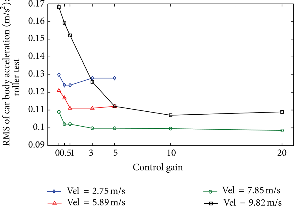
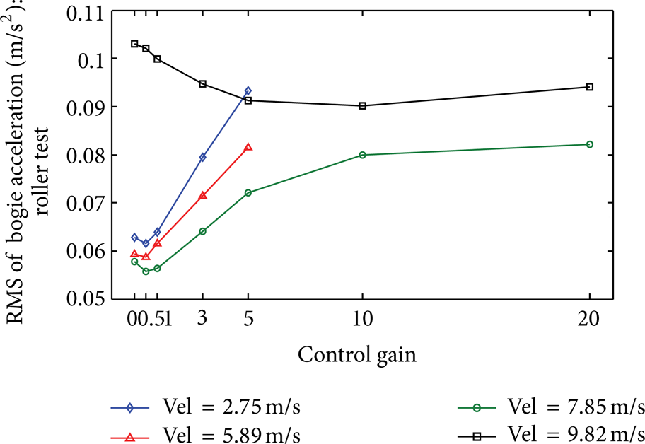
Despite the fact that research on semiactive and active suspensions has been conducted since the early 1980s and continues to this day, a long time is being consumed for its commercialization. The reason is that the size of facilities and vehicles is larger compared to automobiles, and it is not easy to design an adequate controller due to the unique running characteristics of railway vehicles that is rolling on rails. Therefore, before applying the MR damper on full scale railway vehicles to improve ride quality, a 1/5 scaled railway vehicle was used for numerical simulation and to experimentally verify the control performance of MR dampers. Before producing a full scale MR damper, a 1/5 scaled MR damper was produced in order to confirm the performance of MR damper. The 1/5 scaled MR damper was applied to the numerical model of the half-car railway vehicles with 9 degrees of freedom, as can be seen in Figure 6 [13, 14]. Formula (2) are formulas expressing the motion equation of railway vehicles in a matrix equation, and the characteristics of MR dampers were applied to this formula before conducting the semiactive control. Figures 7 and 8 are results of performing skyhook control regarding the running velocity of 2.75 m/s, 5.89 m/s, 7.80 m/s, and 9.82 m/s. From the numerical simulation results, the vibration reduction effect appeared noticeably as the control gain increased from 0 to 20. However, the vibration effect of the car body appeared to be the same regardless of the increase of the gain after reaching a particular gain. For bogie vibration, control effect appeared in certain very small gains; however in gains over a certain value, the control effect appeared to be very small and even deteriorated in some instances.
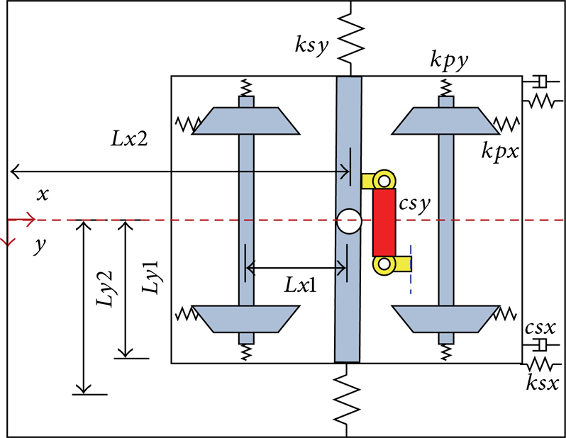
The simulation model of half-car railway vehicle.

RMS of car body acceleration according to velocity (simulation).

RMS of bogie acceleration according to velocity (simulation).
Consider
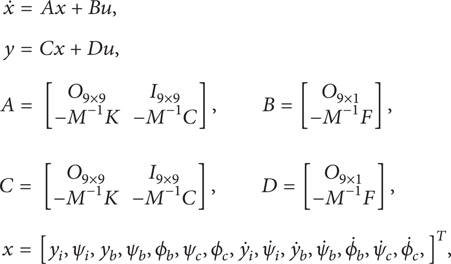
where x is the state vector representing the system state and includes n elements for the n-degree system and where A, B, C, and D represent the system matrix, input vector, conversion constant vector, and direct transmission matrix, respectively (Table 1). u is the input vector.
Degree of freedom of railway vehicle.

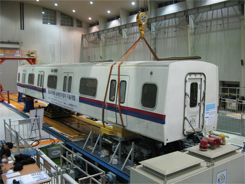
Figure 9 shows a 1/5 scaled half-car body vehicle constructed to experimentally verify the control performance of MR dampers [15]. The MR damper was attached as shown in Figure 10 between the car body and bogie, and a semiactive control performance test was performed by applying the same skyhook control as in the numerical simulation.

A prototype of roller rig with half-car body vehicle system.

A detailed composition of the scaled railway vehicle.
Figures 11 and 12 show the result of performing control on the 1/5 scaled roller rig under the same condition as the numerical simulation. As a test result, the special gain which makes the lowest vibration acceleration level in each speed. This means that when selecting a large gain to improve the vibration reduction performance of a car body, the vibration of the bogie drastically increases in contrast. From such result, it could be known that increased tuning works and tests are necessary according to various conditions when introducing such on actual vehicles.
RMS of car body acceleration according to velocity (test).
RMS of bogie acceleration according to velocity (test).
4. Verification of Performance of Real Semiactive Suspension
4.1. MR Damper for Field Test
The MR damper to be attached between a full scale car body and bogie was developed based on the research result using the 1/5 scaled rolling-stock and the performance was confirmed through a test. Based on the research result by using the 1/5 scaled MR damper, the full scaled MR damper was designed and produced as shown in Figures 13 and 14 by considering the size attachable between the car body and bogie and the response speed of 0.3 m/s with a maximum value of 15 kN.

Main components of test sample of MR damper.
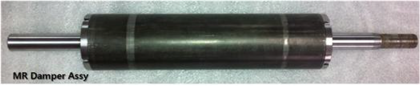
Assembly of MR damper.
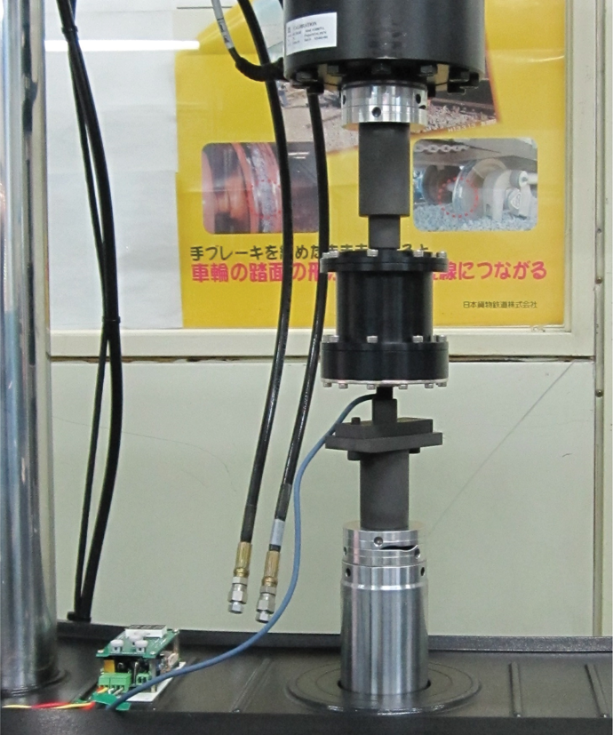
A performance test was conducted on the manufactured MR damper before attaching on the rolling-stock. The performance test of the damper was conducted by various input currents of the MR damper with the displacement of ± 15 mm. Figure 15 is a result of the MR damper performance test, showing the lines of velocity force and displacement force. As a result of the performance test of the MR damper, the maximum damping force appeared to be 15 kN, obtaining the result suitable to the objective of the design. This test result was used for semiactive control by finding the interaction formula between the force and current in the same method as the reduced MR damper.

Performance test of MR damper for semiactive suspension.
4.2. Performance Verification of Semiactive Suspension Using Roller Rig
Before conducting the field test of rolling-stock applying the MR damper, a test was performed on the roller rig, by replicating the same field test running conditions, in order to experimentally verify the vibration control performance of the car body. Roller rig is in a structure supporting the equipment being tested by loading the wheel of the rolling-stock on a roller which represents the rail. Figure 16 is a roller rig used in this research, which is an experimental device that makes the test evaluations and replication of the dynamic characteristics, such as ride quality or running stability of the bogie of the rolling-stock in a laboratory environment.
The layout of full scaled roller rig.
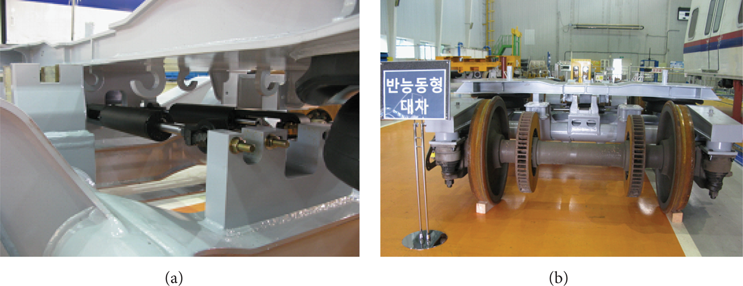
In order to verify the vibration control performance of the MR damper, which is an element of semiactive suspension, a stability evaluation and vibration characteristics analysis of the test bogie attached with a passive suspension was conducted. Figure 17 shows the image of a passive damper attached on the intermediate speed rolling-stock test bogie.

Attachment of passive damper and assembly of passive test bogie.
The test of the bogie attached on this passive damper was conducted with the objective of obtaining reference data to compare the vibration control performance of the test bogie applied with a MR damper. First, a critical speed test was conducted in order to evaluate the stability of the passive test bogie. The lateral displacement and vibration acceleration of a bogie frame and the vibration acceleration of the car body were measured while gradually increasing the roller velocity by 20 km/h per minute in a nonexcitation condition. The speed causing rapid change of the measurement data due to the snake motion occurrence was designated as the critical speed by analyzing the measurement data according to the roller speed. The test result shows that the critical speed of the passive bogie was 193 km/h, in which the vibration of the car body and bogie rapidly increased, as can be seen in Figure 18. Thus, the test velocity on the roller rig of the test bogie, where the semiactive suspension is to be applied, has been established as 150 km/h by considering the fail-safe of the controller.

Limit speed test (passive suspension).
Next, a vibration characteristics test was conducted according to the lateral roller excitation while running in the speed of 150 km/h on a roller rig. The roller excitation was tested by applying the track irregularity data measured during the field test, and Figure 19 shows the vibration characteristics test result of the passive bogie. The RMS value of ride quality was obtained by applying the frequency weighting on the lateral vibration based on the UIC 513 R standard, and the ride quality with the passive bogie was evaluated to be 0.089 m/s2 (98.9 dB).
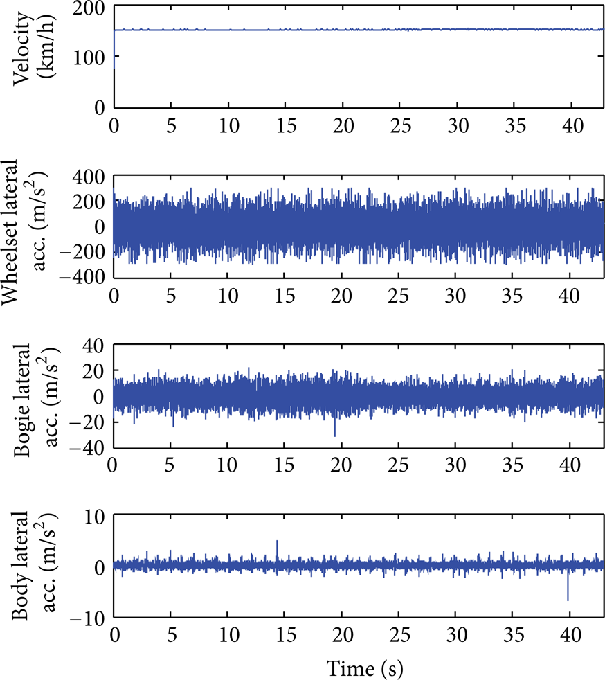
Running stability test (passive suspension).
The test bogie control performance test applying semiactive suspension was conducted under the same condition as the passive test bogie by replacing the previous passive damper to MR damper, as shown in Figure 20. First of all, the evaluation on stability of the test bogie was performed under a condition of not attaching the MR damper by assuming the failure of semiactive suspension, and the result appeared as in Figure 21. As a result of the fail-safe test of the test bogie attached in the MR damper, the critical speed which shows the rapid increase of the vibration of car body and bogie appeared to be 153 km/h due to the snake motion occurrence of the wheelset. This result shows the availability of running in the 150 km/h level, which is the highest operational speed, thus, the procurement of sufficient running stability.
Attachment of MR damper and assembly of semiactive test bogie.

Fail-safe test (semiactive suspension).
A vibration control performance test of the test bogie applying the MR damper was performed next, and the same test condition was used as the bogie with passive damper. The running vibration characteristics of the test bogie applied with the MR damper is as shown in Figure 22, and the car body ride quality appeared to be in the level of 0.068 m/s2 (96.7 dB).
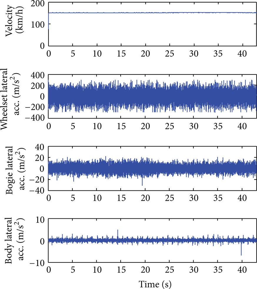
Running stability test (semiactive suspension).
When examining the result of conducting a test by attaching the passive and semiactive suspension under the same running condition and other conditions in detail, it can be confirmed that vibration is controlled as in Figures 23 and 24. As can be seen in Table 2, the semiactive rolling-stock applied with the MR damper showed improved ride quality of 23.6% compared to passive rolling-stock due to the vibration control performance.
Vibration control performance between passive and semiactive suspension.


Acceleration of car body between passive and semiactive suspension.
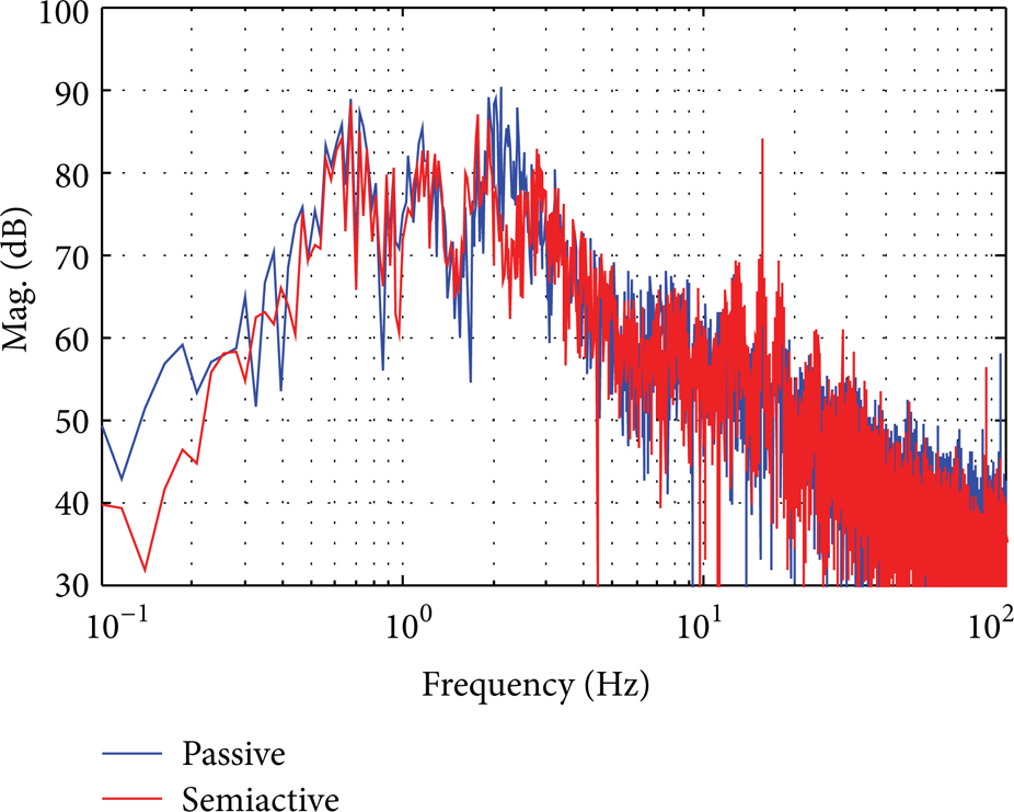
Frequency response of car body on control.
5. Conclusion
Recent railways have achieved significant development in the ride quality or running velocity compared to railways years before the present day. In particular, research on active and semiactive suspension controlling the vibration of a car body had been conducted from long ago to improve ride quality. Nonetheless, because of the large size of railway vehicles and the difficulty in constructing test facilities to conduct tests, a long time is being consumed for its commercialization. This research was conducted to reduce vibration of the car body of railway vehicles and described the result of applying MR dampers laterally to secondary suspension. In order to verify the control performance of the MR damper, a 1/5 scaled railway vehicle model was constructed, and numerical simulation and tests were performed. Based on the research results with 1/5 scaled MR damper, the full scaled MR damper for experimental test was produced and attached between the bogie and car body of a full scaled vehicle, and vibration control was conducted to improve ride quality on the roller rig. As a result, the following conclusion has been deducted.
9-DOF dynamic analysis model and 1/5 scale roller rig were established and the numerical simulation and experimental test were conducted before applying the control on a full scale semiactive suspension. As a result, the skyhook control method appeared to be easy to realize, an adequate gain value was confirmed to exist to control the vibration of the car body and bogie in various running speeds, and the causal relationship regarding the numerical simulation and test results appeared to be highly similar.
A full scale MR damper was designed and produced based on the researches using 1/5 scaled railway vehicles and a vibration control performance test based on the MR damper was performed on a running tester by attaching such damper between the bogie and car body. As a result, a 24% vibration reduction rate was confirmed. However, for further outstanding control performance, increased tuning work of the controller seems to be needed.
As a result of performing the skyhook control applying the MR damper when preparing a control gain set-up standard according to velocity, outstanding control performance compared to price was shown. Additional research is expected to be conducted on control methods different from the control performance of MR dampers according to various running speeds of full scale railway vehicles. As such, commercialization will be more promptly achieved if research on controls applying MR dampers is to be continuously performed.
Conflict of Interests
The authors declare that there is no conflict of interests regarding the publication of this paper.
Footnotes
Acknowledgments
This research has been supported by the program of the Ministry of Trade, Industry and Energy (MTIE), Grant no. 10035315 and in part by research Project of “Development of active suspension for railway vehicle.”