
Abstract
The global positioning system (GPS) is a popular choice for accurate location sensing and is often used in navigation systems. However, GPS fails to operate inside buildings because satellite signals are blocked. Thus, GPS cannot be used for localization indoors. Moreover, it is difficult to distinguish between the different floors. Research to overcome this problem using the ultrawideband (UWB), radio frequency identification (RFID), and infrared ray (IR) has been conducted. These methods, however, have drawbacks, such as the need for an additional communication module and database. Wireless local area network (WLAN) access point (AP) is widely installed at various locations, and using these WLAN APs can be a viable alternative. The proposed system in this paper indicates the location information in the service set identifier (SSID) of virtual AP. Therefore, merely by scanning the WLAN signals, mobile users can detect their location indoors.
1. Introduction
The advancement of information and communications technology and mobile radio communication network has rendered it possible to obtain the information regarding the location of a user. Thus, location based services (LBS) are gaining ground. GPS is commonly used to estimate a user's location. However, weak reception of signals indoors makes it difficult to pinpoint the location indoors. Further, it is difficult to distinguish between the floors within a building [1].
The proposed system in this paper indicates the floor information in the service set identifier (SSID) of AP, besides indicating the GPS coordinates including the latitude and longitude. The SSID is an important scanning parameter, along with the name of the network. While scanning, a mobile node (MN) searches for an SSID and may build a list of SSIDs for presentation to the user. Therefore, by simply scanning the WLAN signals, an MN can detect its own location indoors. The mobile user's latitude (Y-coordinate), longitude (X-coordinate), and floor (Z-coordinate) information is known, enabling 3D localization. Furthermore, the proposed system can be applied to all wireless access methods including the UWB, RFID, IR, and WLAN.
There have been researches to estimate the location indoors using various methods like the UWB, RFID, IR, and WLAN. Methods which use the UWB, RFID, and IR have a weakness; they require an additional communication module [2–7]. To tackle this problem, a widely installed AP is used to develop an alternative indoor localization scheme. Currently, a fingerprint method using an AP is widely in use for indoor localization [8, 9].
However, the conventional fingerprint method using AP is disadvantageous, as it requires a database (DB) server that stores all the location information [10–12]. Furthermore, several reference points should be set in advance to gather received signal strength indication (RSSI) that forms a fingerprint DB (a signal pattern map) [13]. Therefore, when the position of an AP or the neighboring environment changes, the RSSI information in each location has to be measured again and modified, to be updated in the DB server. Further, an MN that wants to estimate its own location must access the DB server or download the fingerprint DB beforehand, to compare the DB information with the RSSI and AP information [14, 15].
2. Background
2.1. Distance Estimation Using RSSI
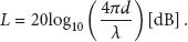
A localization scheme uses both distance estimation using RSSI and position estimation using trilateration. To plot the location of a mobile user, the MN sends a “probe request message” to WLAN AP, requesting information about SSID. “Probe response message,” which is the response by an AP, includes an SSID [16]. RSSI is an indication of the power level being received by the antenna. Distance between the AP and the MN can be estimated using RSSI [17–19]. Distance estimation using the path loss model is as follows. Distance estimation method using WLAN RSSI utilizes the “free space loss” formula that uses the distance between antennas to calculate the path loss. Pass loss L is computed as shown in the following:

2.2. Trilateration
A trilateration method is used to estimate the location, as shown in Figure 1.

Trilateration (MN's ideal location versus MN's real location).
Trilateration is a method that uses the distances between MN and three known reference points to estimate MN's position. We know the distances (


Distance error of free space loss model.
3. Proposed System
The proposed system in this paper indicates the location information (latitude, longitude, and floor) in the SSID of virtual AP. Generally, APs are fixed in a particular position without considerable movement; the location of APs can be plotted with latitude, longitude, and floor information.
The position (latitude and longitude coordinates) of APs installed indoors can be obtained externally using GPS coordinates and floor plan. Once we determine the GPS coordinates of the face of the exterior wall and the floor plan, we can calculate the GPS coordinates of a specific location. The circumference of Earth along the equator is 40,075.017 km in length; hence, the distance between two consecutive longitudes (1 degree) is 109.8 km. This paper used GPS coordinates of six-digit precision. GPS coordinates of one-digit decimal point have a margin error of 11 km, while those of six-digit decimal points have a margin error of only 11 cm. GPS is a satellite navigation system that provides the user's current location by receiving signals from the satellite. Therefore, commercial GPS has an error margin of about 10 m while plotting GPS coordinates on the map, because of reception errors. This paper, however, uses the absolute value of the GPS coordinates on the map and not the measured GPS signals; therefore, there is an 11 cm error margin only.
In this paper, a brace “
AP's SSID should retain the same name to provide the mobility in the extended service set (ESS), which is composed of several basic service sets (BSSs) [16]. Therefore, under the proposed system, each AP, which has multiple SSIDs (SSID 1, SSID 2), operates as a virtual AP. Hence, SSID 1 of an AP, which forms one ESS, should be set with the same name. Further, SSID 2 is used to display the location information of each AP.
The configuration of the proposed system is shown in Figure 3. Here, an AP has two SSIDs, operating like two virtual APs.
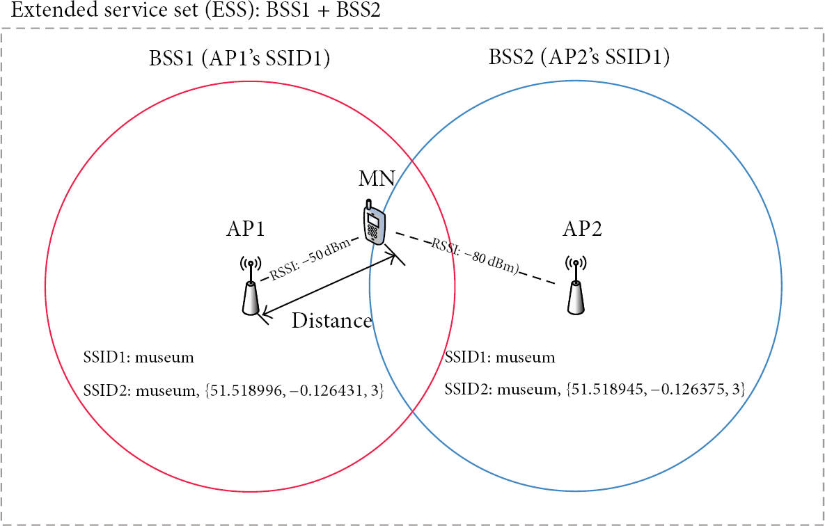
Configuration of the proposed system.
4. Experiment Results
4.1. Location Error
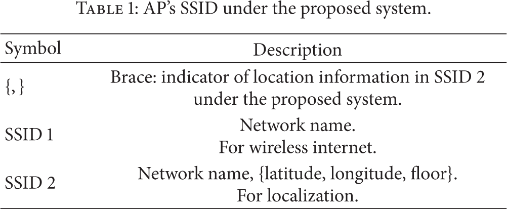
The proposed system uses SSID for localization in AP. As is evident from Table 1, the SSID indicates the name and the location information including the latitude, longitude, and floor under the proposed system. The brace “
AP's SSID under the proposed system.
Location estimation was tested with one to three APs, with 10 m interval between the APs. As demonstrated in Figure 4, the average distance error of localization was 3.8 m with one AP, but it reduced to 2.1 m with the trilateration method using three APs.

Distance error of localization.
4.2. Demonstration of 3D Indoor Localization
Google Mobile Maps provides indoor maps for several major buildings in the world, and the number of buildings for which such maps are provided is increasing [20]. The proposed method was tested for localization within the British Museum, for which Google provides indoor maps. We opted for a room with the same size as “room 3 free exhibitions (or clocks and watches)” of the British Museum ground floor (or third floor) and assumed this to be the British Museum. Figures 5 and 6 display the experimental setup of the British Museum. The location information (latitude, longitude, and floor) of “room 3 free exhibitions (or clocks and watches)” was set in the SSID of AP1, AP2, and AP3, and the 3D indoor localization was tested.
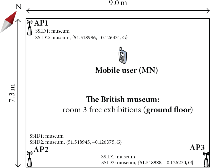
Experimental setup (the British Museum: ground floor).

Experimental setup (the British Museum: third floor).
Figure 7 shows the SSID of the AP that was extracted by scanning the WLAN signals near the MN. MN extracts position information from three strongest signals among the received SSIDs with location information. This information is used to estimate the distances between AP1 and MN, AP2 and MN, and AP3 and MN. For example, the figure of latitude 51.518996, longitude −0.126431, and the third floor can be detected in SSID “museum,

Extracting the location information in SSID by scanning the WLAN signals (the British Museum: ground floor versus third floor).
The calculated location information can be plotted on a map. Figures 8 and 9 are examples of the calculated location information (latitude, longitude, and floor) marked on Google Mobile Indoor Maps. When the floor information is set as “G” in the SSID of the AP, MN recognizes its current location as ground floor, as in Figure 8. Likewise, when the floor information is set as “3,” MN recognizes its current location as third floor, as in Figure 9.

3D localization in Google Mobile Indoor Maps (the British Museum: ground floor, room 3 free exhibitions).

3D localization in Google Mobile Indoor Maps (the British Museum: third floor, clocks and watches).
5. Conclusion
The proposed system in the paper displays the GPS coordinates and floor information in the SSID of virtual AP, without any additional equipment or communications module to detect MN's own location. A mobile user scans the nearby WLAN signals to collect the SSID of AP and the RSSI information. The distances are estimated using the received SSIDs, and MN's own position is estimated from the distances from three sides (APs). By simply scanning the WLAN signals, MN can detect its own location. Furthermore, the proposed method transmits signals that include the position information in a periodic beacon, which can be applied to all wireless access methods like UWB, RFID, IR, and WLAN. Thus, the proposed method can be applied in real life without modifying the AP's software and hardware.
Footnotes
Conflict of Interests
The authors declare that there is no conflict of interests regarding the publication of this paper.
Acknowledgment
This research was supported by Hallym University Research Fund, 2014 (HRF-201402-009).