
Abstract
A lateral control method is proposed for intelligent vehicle to track the desired trajectory. Firstly, a lateral control model is established based on the visual preview and dynamic characteristics of intelligent vehicle. Then, the lateral error and orientation error are melded into an integrated error. Considering the system parameter perturbation and the external interference, a sliding model control is introduced in this paper. In order to design a sliding surface, the integrated error is chosen as the parameter of the sliding mode switching function. The sliding mode switching function and its derivative are selected as two inputs of the controller, and the front wheel angle is selected as the output. Next, a fuzzy neural network is established, and the self-learning functions of neural network is utilized to construct the fuzzy rules. Finally, the simulation results demonstrate the effectiveness and robustness of the proposed method.
1. Introduction
Intelligent vehicle is an important part of the intelligent transportation system, and lateral control is one of the core issues in the domain of intelligent vehicle autonomous navigation. The purpose of lateral control is to track a desired trajectory according to the control strategy while ensuring the vehicle driving safety and riding comfort. Because of the parameter uncertainty of lateral control system and the strong external disturbance, the lateral control of intelligent vehicle becomes a key point for the whole vehicle control, and it is important for many vehicle control systems, that is, autonomous emergency braking (AEB), electronic stability program (ESP), and so forth.
At present, researches on intelligent vehicle lateral control method can be divided into three categories: the control method based on model, the control method based on nonlinear theory and the method based on intelligence. In the first category, the desired trajectory tracking is realized by the PID [1] and optimal control method [2, 3] based on a vehicle linearized model. The second category includes robust control [4, 5], predictive control [6, 7], sliding mode control [8, 9], self-adaptive control [10, 11], and so forth. For robust control, it has a good control effect on a given system with parameter uncertainty. For predictive control, the performance index function can be optimized by the prediction of relative position in the prediction time domain. For sliding mode control, the system motion track can be driven and limited in a specific sliding manifold by applying discontinuous control law. For the self-adaptive control, this method determine the current working state of the controlled object, optimize the control criterion, and generate the adaptive control law by collecting the information continually in the control process. Then the optimal working condition of the control system can be maintained automatically. The third category includes fuzzy control [12–14] and neural network [15, 16]. For fuzzy control, control effect is optimized through fuzzification, fuzzy inference, and defuzzification. For neural network, this method achieves the self-learning and self-organizing ability by simulating the human brain structure and the function of the nervous system.
Based on the reasons above mentioned, a lateral control method of intelligent vehicle is proposed in this paper based on the combination of fuzzy control, neural network, and sliding mode control. The sliding mode switching function and its derivate are selected as two inputs of the controller, and the front wheel angle is selected as the output. On the one hand, this method maintains the strong robustness of the sliding mode control for the system parameter perturbation and external interference. On the other hand, this method maintains the advantage of fuzzy control which does not rely on mathematical models. By introducing neural network, the ability of adaptive learning and organization is improved, and it can make up the shortcomings of fuzzy control. Finally, the control signal can be smoothed, and the chattering phenomenon in the conventional sliding mode control system can be alleviated.
2. Modeling and the Fusion of Errors
2.1. Establishment of the Vehicle Lateral Control Model
A vehicle lateral control model should be established before the lateral controller is designed. In this paper, the influence of the steering system is ignored, the front wheel angle δ f is selected as the input of the control model, and the lateral error y L and orientation error ∊ L are two state variables in the control model. Ultimately, the lateral control model with uncertainty and disturbance is established. And it can be expressed as

where

where

2.2. Determine the Errors of the Vehicle at Look-Ahead Distance L
In order to track the desired trajectory, a tracking system based on the visual preview is adopted in this paper. This system contains a CCD camera, which collected the information about the road ahead. And the information is transmitted to the on-board computer in real time. The geometry diagram is shown in Figure 1.

Geometry diagram of the intelligent vehicle and its reference trajectory.
In order to calculate the lateral error and orientation error, Figure 1 is simplified. The simplified geometry diagram is shown in Figure 2. O denotes the intersection of the longitudinal and lateral center line, O l denotes the visual preview point, O l X l is the line which goes through O l and parallel to the centerline OX, and P(x0, y0) is the intersection of the reference path tangent and O1X1.

Simplified Geometry diagram of the intelligent vehicle and its reference trajectory.
The lateral error is defined as

where w1 is the width of the image. In (4), the lateral error is a pixel value, so it needs to be convert to an actual lateral error:

where γ is the proportionality coefficient of the actual value and pixel value.
At the intersection, the tangent of the reference path curve is defined as:
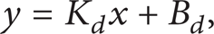
where K d is the slope of y, B d is the intercept of y, the orientation error is defined as:

2.3. Fusion of the Lateral Error and Orientation Error
If the lateral error, orientation error and their derivatives are selected as the inputs of controller, the input dimensions will be increased, and the structure of fuzzy neural network will be larger. This complex structure will lead to a slow learning, and the application of the fuzzy neural network will be limited. Therefore, in order to reduce the input dimensions of the fuzzy neural network, the lateral error and orientation error are fused as an integrated error.
First, the experimental data is filtered through the Kalman filter. The lateral error, the orientation error and the front wheel angle are normalized to [− 1, 1]. Then, the lateral error and orientation error are processed by nondimensionalization. These can be described as
where

where λ c is the weighting coefficient and C e is the integrated error.
3. The Design of Fuzzy Neural Network
3.1. The Lateral Control System Structure
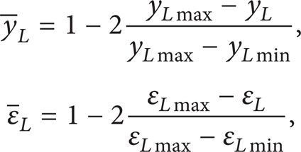
The structure diagram of the lateral control system is shown in Figure 3. A fuzzy neural network controller is adopted as the lateral controller in this control system. The sliding mode switching function s and its derivative are selected as the inputs; front wheel angle is chosen as the output.
The structure diagram of the lateral control system.
3.2. The Sliding Mode Switching Function
The switching function is the combination of the integrated error and its derivative. It can be described as

The reaching condition of SMC (sliding model control) is

where c1 is the sensitivity factor.
3.3. Design of the Lateral Controller
In the fuzzy neural network, the fuzzy variable sets, membership functions, and fuzzy control rules are constructed by the multilayer feedforward network. The fuzzy neural network is optimized by adjusting the network weights after multiple learning.
Theoretically, the more numbers of fuzzy subsets there are the better control performance will be. But if there are too many numbers of fuzzy subsets, the control rules will be more complicated, the realization of the control algorithm will be very difficult. If the numbers of fuzzy subsets are too little, the oscillations and dead zone of adjustment phenomenon will happen. Based on the above consideration, s is mapped to seven fuzzy subsets: NB (negative big), NM (negative medium), NS (negative small), ZO (Zero), PS (positive small), PM (positive medium), and PB (positive big). Similarly,
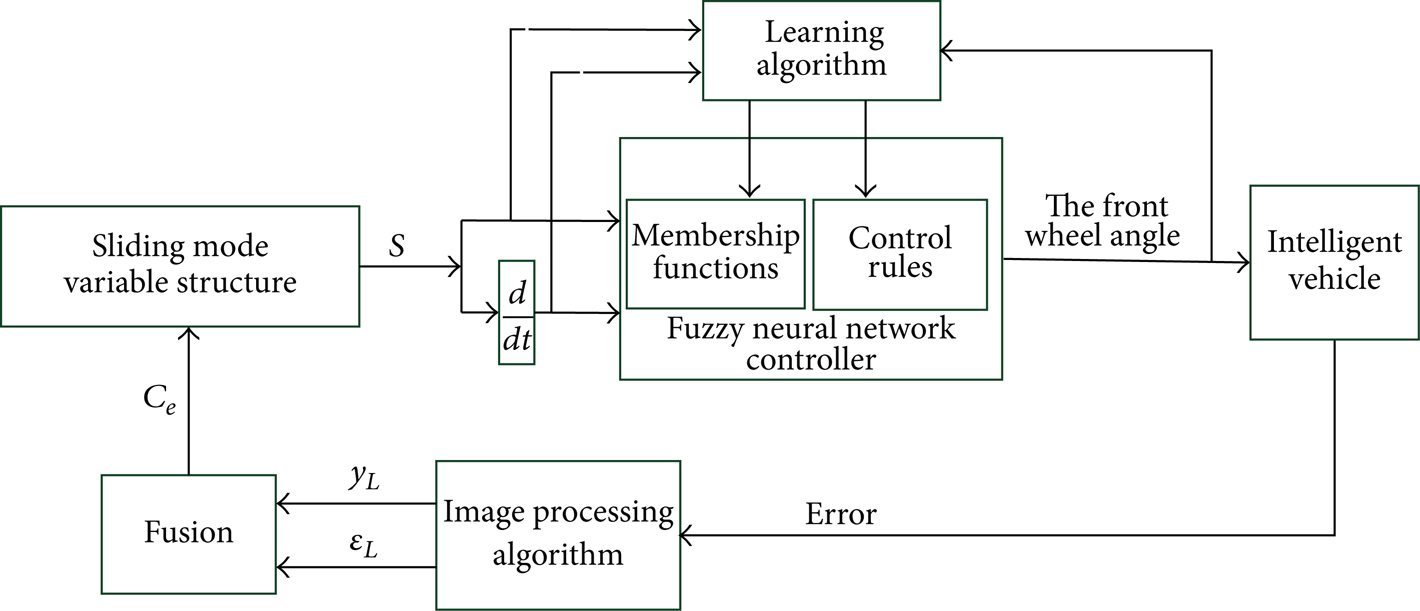
In this paper, a fuzzy neural network based on Takagi Sugeno (T-S) model is applied. It can effectively express some complex system and accurately process nonlinear system. The multilayer feedforward neural network is utilized. Each layer in the network completes a specific task and sends data to the next layer. The structure diagram of the fuzzy neural network is shown in Figure 4.
The structure diagram of the fuzzy neural network.
The first layer is the input layer; this layer accepts the error and its derivative. The function of this layer is to transmit the input parameters of the sample.
The second layer is the membership function layer. This layer completes the fuzzification. The numerical magnitude of the input is transformed into a fuzzy quantity, which determines the membership degree of the input numerical magnitude. After comparison, a good performance of smoothness can be achieved by using the Gaussian function as a membership function in the T-S fuzzy neural network; it can be expressed as
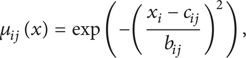
where x is the numerical magnitude of the input, c is the center of the membership function, and b is the width of the membership function. i = 1, 2; j = 1, 2…7.
The third and fourth layer are the fuzzy reasoning layers. They realize the optimization of the membership function and the formation of the fuzzy rules. In this paper, 49 fuzzy rules are formed based on the sample data in the fuzzy neural network. R l represents the l rule, it can be expressed as
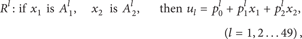
where A1 l and A2 l are the fuzzy sets in R l , respectively. u l is the output of R l . Finally, the weight of fuzzy rule ω l is exported from the fourth layer.
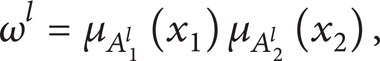
where μA i l (x i ) is the membership degree that x i belongs to A i l .
The fifth layer is the defuzzy layer; it completes the task of defuzzification and exports the control quantity. If n control rules are activated, the total output can be obtained as
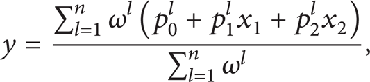
where p is the coefficient of the neural network, 1 < n ≤ 49.
3.4. Learning Algorithms of the Fuzzy Neural Network
In the fuzzy neural network, the sample sets are formed by the experiment data. The sample sets are used to design and optimize the network. This process is called learning process. The essence of learning algorithms is that make the change of weights become little and finally attain the minimal error. Gradient descent method is applied widely and has a good performance; the weight can be constantly updated for multisamples by continuous training, and it will improves the self-adjusting ability of the control rules. So this method is often applied in the process of parameter adjustment. The membership functions and fuzzy rules are appropriate candidates for gradient descent method. Therefore, in this paper, the gradient descent method is applied. It is shown as follows.
Calculation of the error

where y d is the expected output of the network, y c is the actual output of the network, e is the error between the expected output, and the actual output.
Modification of the coefficient
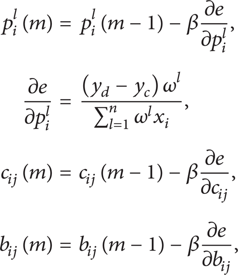
where β is the learning-ratio of the network.
The membership functions of s are shown in Figure 5. The optimized membership functions of s are shown in Figure 6. We can see the membership functions of s are optimized by gradient descent method through the comparison of Figures 5 and 6.

The membership functions of s.

The optimized membership functions of s.
4. Simulation Results
In this paper, the sliding mode switching function s and its derivative are adopted as the inputs of the controller; the front wheel angle are adopted as the output. The real vehicle experiment which corrected the lateral error and orientation error is completed in the real road environment. The data obtained in this experiment are used as the original sample data of the controller. The main parameters of the model are taken from the experimental vehicle of DLUIV-1 in Figure 7, which was designed by our research group. The parameters of the vehicle model used in the simulation are shown in Table 1.
Vehicle parameters.


DLUIV-1.
In this paper, the feasibility of the proposed method is verified by three groups of simulation test. First, in the initial state, the lateral error is set as 0.2 m, the orientation error is set as 0.1 rad, the vehicle's speed is set as 5 m/s, and the look-ahead distance is set as 10 m. The reference path used in the simulation test is shown in Figure 8.

Reference path.
Figure 9 shows the response results (the front wheel angle) by different control methods. The red line denotes the results of the vehicle controlled by SMC (sliding model control), and the blue line denotes the results of the vehicle controlled by the method proposed in this paper. For SMC, it can be seen that the chattering phenomenon is obvious when the path curve is changing very fast. On the contrast, the chattering phenomenon is alleviated by the proposed method.
The response of the front wheel angle.
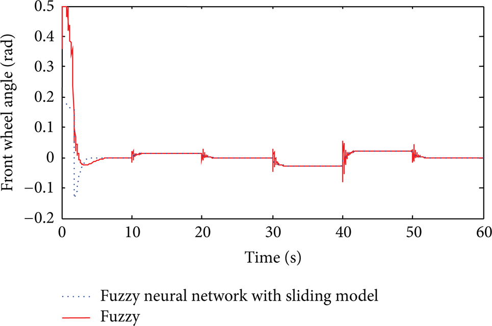
Second, in the initial state, the lateral error is set as 0.8 m, the orientation error is set as 0.5 rad, the vehicle speed is set as 5 m/s, and thelook-ahead distance is set as 30 m, the curvature of the simulation path is set as zero. By comparing the fuzzy neural network control method with the fuzzy control method, the response of front wheel angle is shown in Figure 10, the response of lateral error is shown in Figure 11, and the response of orientation error is shown in Figure 12.

The response of front wheel angle.

The response of lateral error.

The response of orientation error.
From Figures 10–12, the front wheel angle, lateral error and orientation error can be converged under these two control methods. But compared with the fuzzy control method, the response of the vehicle front wheel angle and the change of the errors are smoother under the effect of the proposed method, and the overshoot is decreased. This verifies the proposed method has good ride performance.
Thirdly, a path is designed to verify the robustness of the proposed method. In the initial state, the lateral error is set as 0.8 m, the orientation error is set as 0.5 rad, the vehicle's speed is set as 10 m/s, the look-ahead distance is set as 30 m, and the reference path is shown in Figure 13. The response of front wheel Angle is shown in Figure 14, the response of lateral error is shown in Figure 15, and the response of orientation error is shown in Figure 16.

Reference path.

The response of front wheel angle.
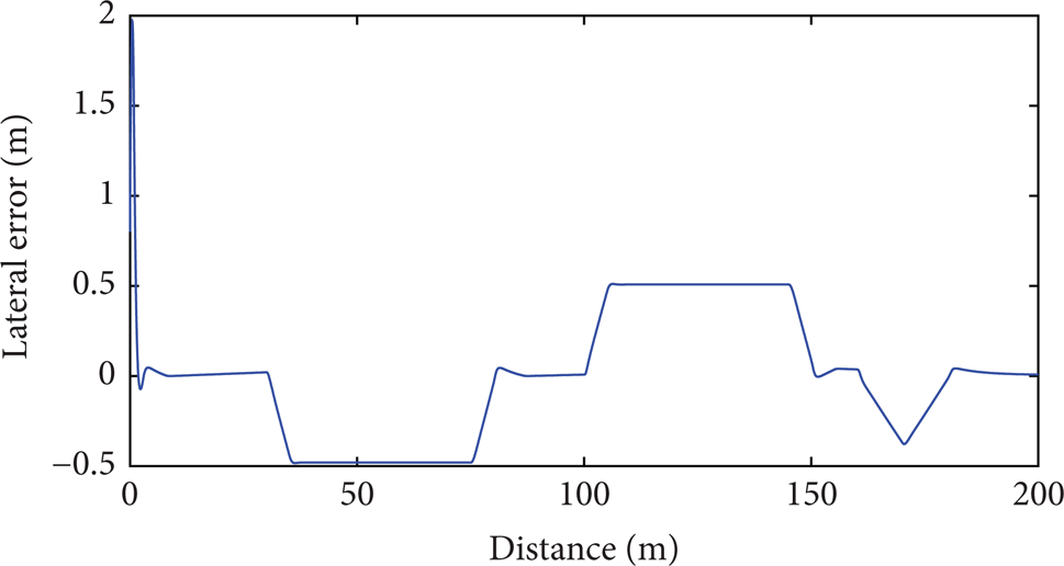
The response of lateral error.

The response of orientation error.
From Figures 14–16, it can be seen that the response curve of the vehicle front wheel angle is smoothed and the overshoot is decreased under the effect of the proposed method. The lateral error and orientation error are closed to zero in straight line segment, and the error can be maintained in a stable value when the path curvature is constant; this verifies the good curve tracking ability of the proposed method. The method also has a good performance when the curve curvature is changing fast. The above results show that this control method has a strong robustness.
5. Conclusions
This paper proposed a lateral control method for intelligent vehicle based on the combination of fuzzy control, neural network, and sliding mode control. By introducing neural network, the control rules were more objective. By introducing sliding mode control, the strong robustness for the system parameter perturbation and external interference was maintained. By combining with fuzzy control, the chattering phenomenon in the conventional sliding mode control system was alleviated. The simulation verified the good trajectory tracking performance of the proposed control method.
Conflict of Interests
The authors declare that there is no conflict of interests regarding the publication of this paper.
Footnotes
Acknowledgments
This work is supported by the National Natural Science Foundation of China (Grant nos. 51107006 and 61203171) and China Postdoctoral Science Foundation (Grant nos. 2012M510799 and 2013T60278).