
Abstract
The elastic-plastic collapse of circular beams under uniform lateral pressure with an initial imperfection represented by a combination of different modes and amplitudes and with varying material properties is analysed from a computational viewpoint. The work is stimulated by a number of accurate experimental tests recently performed and it is found that both the initial imperfection and the material inhomogeneity along the beam axis can affect the collapse and produce a sensible variation in the carrying capacity of the structure on account of the changes between the underlying buckling modes. This can give reason for some apparently anomalous observed experimental results.
1. Introduction
The foundation of the analytical theory for the postbuckling behaviour of structures in the plastic range is essentially due to Hutchinson [1], but with the advent of powerful computers, a large number of studies based on materially and geometrically nonlinear numerical procedures have been performed.
The present study, moving from the analysis of cylindrical shells employed in the oil industry and nuclear power plants, shows a limit behaviour in collapse of circular rings under uniform external pressure that can be considered an extension to the elastic-plastic range of the phenomenon of change in buckle patterns in elastic structures studied by Chilver [2] and Supple [3], among others.
In fact, the cross sections of many of these cylindrical shells possess a diameter over thickness ratio, D/t, in the region where failure under uniform external pressure is dominated by both instability and plastic collapse, which means that prior to collapse the compressive yield strength of the material is exceeded, followed by deformation and further local yielding.
Moving from some apparently anomalous observed experimental results, the problem is investigated and it is found that both the shape of the initial imperfection and the variation of material properties along the axis can affect the buckling load and produce a reduction in the carrying capacity of a circular beam by accelerating changes in collapsing patterns.
2. Experimental Findings
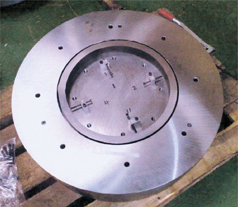
The results from four different circular beams machined at Tata Steel [4] and from the same pipe of diameter D = 457.2 mm, thickness t = 31.75 mm (see Figure 1), are shown in Figure 3, where the displacements are referred to four transducers placed at 0, π/2, π and 3π/2 positions; see Figure 2.

A circular beam specimen.
Specimen equipped with displacement transducers.

Measured radial displacements against the applied pressure for four different rings machined from the same pipe (D = 457.2 mm, t = 31.75 mm).
The experimental setting is described in detail in [5].
The first three cases, namely, (a), (b), and (c), show a limit pressure consistently ranging from 67.6 to 69.5 MPa, while the last one, (d), shows a limit pressure of 55.4 MPa.
At first sight, this anomaly was not followed up and after checking that the transducers were correctly positioned and the instrumentation was functioning properly, its cause was not further investigated.
However, since this behaviour has been found in additional instances, the need to understand the possible causes of such findings has led us to study more carefully the mechanics of the problem.
3. Problem Statement
The problem under analysis can be represented as that of a circular beam subject to a uniform external pressure, as shown in Figure 4.

A circular beam under external pressure.
With reference to Figure 4 a system of polar coordinates is set:

where R is the radius of beam axis. The displacement field is expressed in terms of the radial component, w = w(θ), p being the uniform external pressure.
In order to be general, the collapse of the ring of Figure 4 is here studied under the assumption that the material properties vary along the axis of the beam and that the initial out of roundness can be represented in the form

where n
i
is the number of waves characterising each component of the out of roundness (see Figure 5) and

Sample out of roundness component shapes, n = 2 (left) and n = 3 (right).
In order to account for the variation of the material properties along the beam axis, for the sake of simplicity but without loss of generality, three different material regions, symmetric with respect to the x axis, are defined around the ring circumference, as shown in Figure 6. The amplitudes of these regions for θ ∈ [0, π] are, respectively,


Inhomogeneous material regions.
The representation of the stress-strain curves for carbon steels is assumed in the form of the Ramberg-Osgood (RO) power law [6],

where β is a dimensionless coefficient, which for most engineering cases can be assumed ≥ 5, σ y (j) is the Jth material region yield stress, and ε y (j) is the corresponding strain. Without loss of generality, Young's modulus, E, is assumed to be the same for each material region.
Under these assumptions, the collapse load and the failure modes of the circular beam are the object of the investigation of the next sections. In order to analyse the contributions separately and shed light on the mechanics of the problem, first the influence of the mixed-mode imperfections and successively that of the varying material properties along the beam axis will be considered.
4. Influence of Mixed-Mode Imperfections
The influence of mixed-mode imperfections modelled as in (2) has been analysed by means of the commercial finite element (FE) package ANSYS [7].
Every circular beam was modelled by means of 23040 SOLID185 3D 8-node elements, as shown in Figure 7. Eight divisions were carried out through both the width and the depth of the cross section of the beam. Out of plane displacements of the beam axis were not allowed in order to simulate the testing arrangement [5].
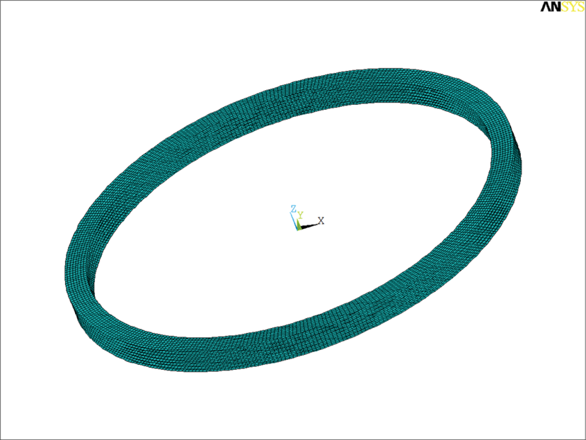
FE modelling of a circular beam.
In general, numerical investigation of the nonlinear behaviour of structures must follow the equilibrium path, identifying and computing the singular points like limit or bifurcation points, whose secondary branches in the equilibrium path must be examined and followed, and this procedure can be adversely affected by any kind of approximation, as shown even in the simplest examples [8, 9]. To overcome difficulties with limit points, displacement control techniques were introduced and for this reason the modified arc-length method was used in ANSYS to follow the load-deformation path [10, 11].
The case studies taken into consideration are those of a circular beam characterised by a diameter of 457.2 mm with D/t ratios equal to 14.40 and 22.85, respectively. The second example represents the ring whose tests results have been presented in Section 2.
The material properties are the following: E = 206.6 GPa, σ y = 561 MPa, ε y = 0.01, and β = 7.625.
From an engineering standpoint, the measured out of roundness on experimental specimens needs to be smoothed and decomposed in its fundamental modes. However, it has been shown in [12] that in the case of many sections commonly used in offshore engineering, the prominent imperfection modes are those characterised by two (n = 2) and three (n = 3) waves.
Therefore, without lack of generality, the analysis has been performed on a combination of two, and three-wave imperfection modes.
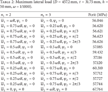
The results are summarised in Tables 1 and 2.
Maximum lateral load (D = 457.2 mm, t = 20 mm, h = 50 mm, and ω = 1/1000).

Maximum lateral load (D = 457.2 mm, t = 31.75 mm, h = 50 mm, ω = 1/1000).
The parameters for the control of the nonlinear FE analysis have been set assuming that the maximum initial load is 1.2 times the value deriving from the analytical expression in [13] and the number of initial substeps is 100.
It is worth noticing that in the case of the ring with D/t = 14.40, the increment in the collapse load which occurs for a pure three-wave initial imperfection with respect to two-wave is about 35%, whereas in the case of the ring with D/t = 22.85, the corresponding increment is about 21%.
It can be also noticed that in the first case, that is, for D/t = 14.40, on average the increment in the collapse load for a combination of imperfection modes
Figures 8 and 9 show both the load-displacement plot and the deformation at impending collapse from FE analyses for the limit cases of pure two and pure three-wave initial imperfection (D = 457.2 mm, t = 31.75 mm).

Results from FE analyses of Table 2 (

Results from FE analyses of Table 2 (
It is worth noticing that in the case of the circular beam with D/t = 22.85, a few relatively swift variations in the maximum load increment can be sporadically recorded (
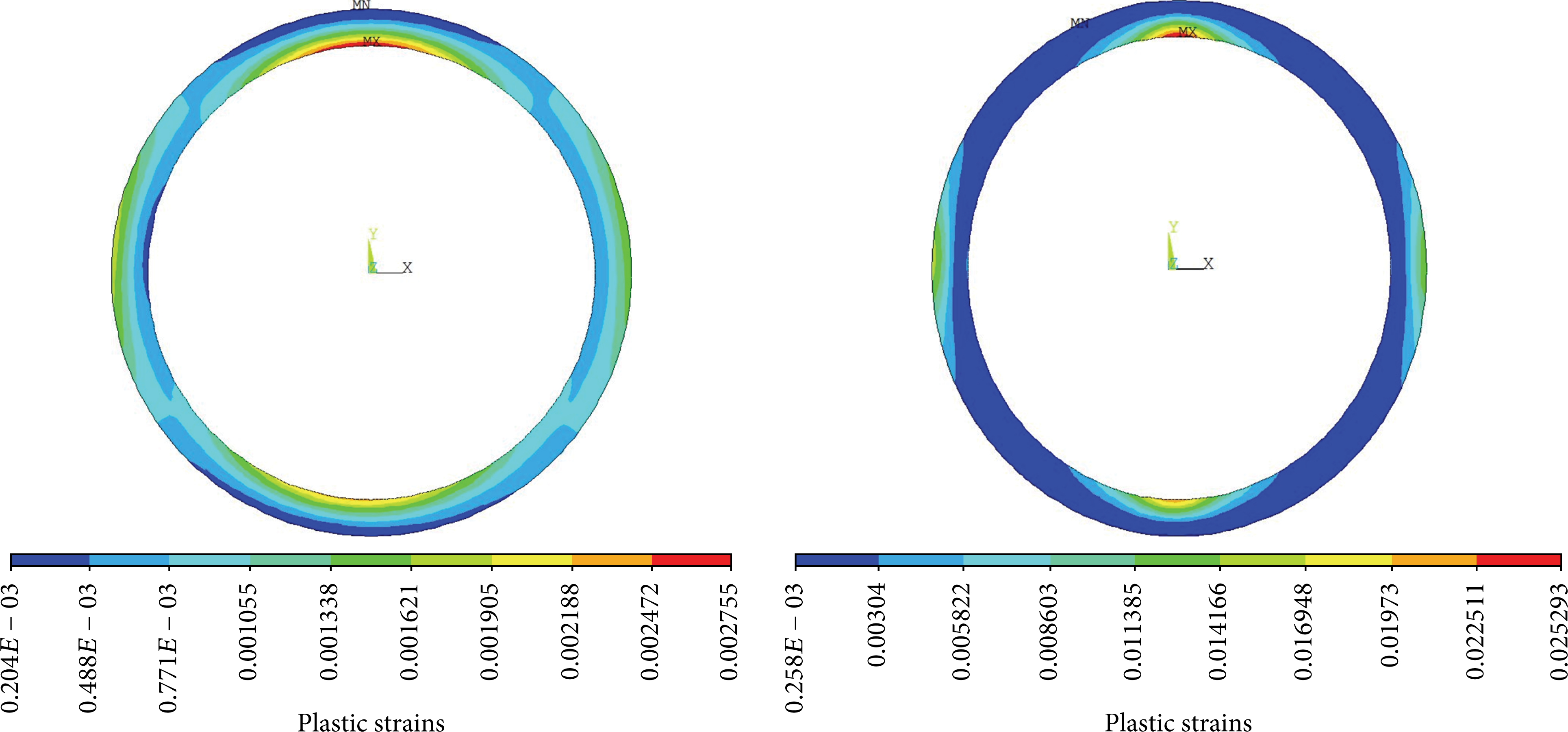
Results from FE analyses of Table 2 (
Overall, the results from Table 2 show that the influence of mixing initial imperfection modes varies with their relative amplitude and offset, but the increment in the collapse load deriving from the presence of the mode n2 = 3 does not result proportional to its weight and provides the value of 67.764 Mpa, in line with the results from Figures 3(a)–3(c), only for
For such a reason, it can be inferred that the circular beams tested in cases (a)–(c) of Figure 3, in absence of other experimental disturbances, such as improper sealing of the specimens in the testing rig, are likely to have been shaped in the manufacturing process with a predominant three-wave imperfection. This supposition is also supported by some geometrical and experimental investigations [12, 14].
5. Influence of Material Inhomogeneity
The influence of material inhomogeneity has been conducted on the basis of the problem statement in Section 3 and according to the analytical solutions provided in [15].
With reference to Figure 6 the yield strengths for Regions ① and ③ have been obtained by amplifying the yield strength of Region ②, E = 206.6 GPa, σ y = 561 MPa, ε y = 0.01, and β = 7.625, by a factor of 1.1 and by reducing it by a factor of 0.9, respectively. In this manner, an increase in resistance is attributed to Region ① and a corresponding decrease in resistance is attributed to Region ③.
The analytical treatment of the problem proposed in [15] leads to the determination of a collapse function, f. The function f can be plotted against the lateral load of the beam and the condition f = 0 is attained at impending collapse.
Figure 11 shows the plot of the collapse function, f, versus the lateral load, p, for a homogeneous (dashed line) and an inhomogeneous (continuous line) circular beam for θ
c
= π/4, n1 = 2, n2 = 3, and

Plot of the collapse function, f, versus the lateral load, p, for a homogeneous (dashed line) and an inhomogeneous (continuous line) circular beam as in Table 1 for θ
c
= π/4,
From the plot, it appears evident that for a pure three-wave initial imperfection the collapse load for the homogeneous beam is much lower than the one for the inhomogeneous beam. Moreover, both these values of the collapse load are in line with the experimental findings of Figures 3(a)–3(c) and Figure 3(d), respectively.
This phenomenon can be attributed to an interference between the geometrical and material imperfections. In other words, the variability of material properties along the beam axis can induce a change of the buckling pattern, swinging the failure mode of the beam characterized by an initial imperfection of shape
Most importantly, it is worth underlining that Figure 11 shows the presence of a peak at the red dot which can be considered as a sort of concealed well in the load-yielding plot. This sort of peaks, which can assume a very narrow shape depending on the geometrical and material properties of the beam, can turn sometimes difficult to trace numerically and can contribute to explaining the anomalous results in experimental tests.
6. Conclusions
The elastic-plastic collapse of circular beams under uniform lateral pressure and with various degrees of initial imperfection and varying material properties has been analysed on account of some apparently anomalous experimental findings. It has been shown that both the initial imperfection and material inhomogeneity along the beam axis can affect the collapse modes and produce a sensible variation in the carrying capacity of the structure by trigging the same change between the underlying buckling modes. The presented examples evidently show that the considered problem, far from being rather straightforward as it might appear at first sight, presents several hitches and requires great care in its treatment on account of its intrinsic features, especially in the design and assessment of problems of interest to the nuclear and offshore industry [16–20].
Conflict of Interests
The authors declare that there is no conflict of interests.