
Abstract
A three-dimensional finite element model was employed to simulate the cladding process of Ni-Cr-B-Si coatings on 16MnR steel under different parameters of laser power, scanning speed, and spot diameter. The temperature and residual stress distribution, the depth of the heat affected zone (HAZ), and the optimized parameters for laser cladding remanufacturing technology were obtained. The orthogonal experiment and intuitive analysis on the depth of the HAZ were performed to study the influence of different cladding parameters. A new criterion based on the ratio of the maximum tensile residual stress and fracture strength of the substrate was proposed for optimization of the remanufacturing parameters. The result showed well agreement with that of the HAZ analysis.
1. Introduction
Laser cladding technology is widely used for rapid formation [1, 2], surface modification and processing [3, 4], and parts repair and remanufacturing [5, 6] because of its small heat affected zone, low dilution rate, and strong metallurgical bond between the cladding material and the substrate. As the change of temperature is very steep and the molten pool formed is very small, it is difficult to measure the temperature distribution in the molten pool through experiment. Therefore, the method of numerical simulation is widely adopted [7–11].
Due to the uneven temperature field, the local plastic deformation in the cladding process, and the differences of thermal expansion property between the substrate and the cladding material, huge residual stress can result in the remanufactured parts. Different laser cladding parameters can lead to different temperature field. Consequently, the residual stress field is also different. Residual stress performs great influence on the fatigue properties of the component [12–14]. Hence, the temperature and residual stress distribution characteristics of laser cladding remanufacturing are important for optimizing the parameters of laser cladding and improving the quality of cladding layer.
In the present work, for different parameters (laser power P, scanning speed V, and spot diameter D), the temperature and residual stress distribution during laser cladding remanufacturing process were studied using ANSYS (Ver. 13.0) software. During the simulation, the moving heat source, thermal convection and radiation, phase transition, and fluid flow in the molten pool are considered. The optimization of process parameters for remanufacturing is performed, which can provide a beneficial reference for a better understanding of the complicated metallurgical physical phenomenon in the process.
2. The Finite Element Model Analysis
The substrate material used is 16MnR of 48 mm × 20 mm × 5 mm. The powder of Ni-Cr-B-Si was used as cladding material. Composition (wt%) of 16MnR and Ni-Cr-B-Si is presented in Tables 1 and 2, respectively. The thermophysical properties and mechanical properties of 16MnR [15] and Ni-Cr-B-Si [16] are shown in Tables 3 and 4, respectively. In the remaining temperature range that is necessary for the thermal simulation, the corresponding thermophysical properties are usually obtained by linear interpolation and extrapolation.
Chemical composition of the substrate (wt%).

Chemical composition of the clad material (wt%).

Thermophysical properties and mechanical properties of 16MnR.

Thermophysical properties and mechanical properties of Ni-Cr-B-Si.

According to the micrograph of real cladding bead, the finite element geometric model is built as a cladding bead with shape of circular arc placed on the substrate. In this model, the radius of cladding bead is 1 mm. Because of the symmetry, one half of the model is selected for the analysis, as shown in Figure 1.

Geometrical model of the specimen.
2.1. Thermal Analysis
In this paper, the indirect method is adopted to simulate the temperature and residual stress distribution. The finite element model is shown in Figure 2 with 20544 brick elements and 24056 nodes. A finer mesh was used in the higher temperature area directly below the moving heat source to permit precise calculations of the steep temperature gradients. The thermal brick element Solid 70, which has a 3D thermal conduction capability, is utilized to mesh the entire finite element model. This element has eight nodes with a single degree of freedom (temperature). It is applicable to a 3D, steady-state, or transient thermal analysis.

The finite element model.
2.1.1. Governing Equation
Considering the latent heat of phase transformations, the partial differential equation for the heat conduction during the laser cladding remanufacturing process can be expressed in its most general form as follows [9, 17]:

where ρ, c, and λ are the density, thermal capacity, and thermal conductivity, respectively. T is the function of temperature distribution. Q is the latent heat of phase transformations and t is the time.
2.1.2. Boundary Conditions of the Convection and Radiation
The initial temperature of the specimen is assumed to be 20°C which is the same with environment temperature. Because the temperature of the laser cladding area is very high, the influence of radiation heat transfer cannot be ignored. Therefore, it is necessary to comprehensively consider the effect of convection and radiation heat transfer [18–20]. The overall heat transfer coefficient in this paper is given by references [19, 20] as follows:

where T is the temperature.
2.1.3. Effect on Fluid Flow in the Molten Pool
To account for heat transfer, due to fluid flow in the molten pool, an artificially increased thermal conductivity, which is larger than the value at room temperature, is assumed for temperatures above the melting point [20, 21].
2.1.4. Effect on the Phase Transition
The thermal effects due to phase transition are modeled by taking into account the latent heat of fusion. ANSYS software can consider the influence of the phase change by defining the enthalpy with the elevated temperature. During the laser cladding remanufacturing process, the enthalpy change (ΔH) for transient heat transfer analysis is given by

2.1.5. Heat Source Model
Gaussian heat source is mostly used in the simulation of laser cladding process [22–24]. But Gaussian heat source is a 2D heat source which cannot account for the penetration of the laser. To overcome the shortcomings of plane Gaussian heat source, double ellipsoid heat source model was employed which was expressed by the following equations [20].
For the front heat source,
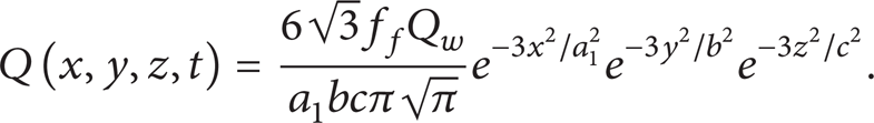
For the rear heat source,

where f f and f r are parameters which give the fraction of the heat deposited in the front and the rear parts, respectively. Note that f f + f r = 2.0. In this study, f f is assumed to be 1.4 and f r 0.6. This is done because the temperature gradient in the front leading part is steeper than that in the tailing edge. Q w is the effective power of the laser. It can be calculated according to the laser power and the absorption efficiency η. The absorption efficiency η is assumed to be 40% for the laser cladding remanufacturing process. The parameters a1, a2, b, and c are related to the characteristics of the laser cladding heat source. The parameters of the heat source can be adjusted to create a desired melted zone according to the laser cladding conditions.
In addition, in order to depict the process of mass transfer, due to powder deposition on substrate, the birth and death technique of the element is applied to thermal analysis. The elements of laser cladding coatings must be killed and then the deactivated elements remain in the model but contribute a near-zero conductivity value to the overall matrix before applying any heat loads. While the heat loads are applied to the laser-scanned region, the dead elements would be activated with the moving heat source gradually.
2.2. Residual Stress Analysis
The same finite element mesh method used in thermal analysis is employed in residual stress analysis, except for the element type (Solid 70 switches to Solid 185) and the boundary conditions. The residual stress analyses are conducted using the temperature history calculated by the thermal analysis. The bottom surface of the specimen is fixed in the vertical direction.
3. Results and Discussion
3.1. Calculation Results of Thermal Analysis
Laser cladding parameters based on the orthogonal design method are shown in Table 5.
Laser cladding parameters.

Figure 3 shows three-dimensional temperature distribution contours of a clad track with pass one (at cladding time t = 8.0 s). It can be seen that great temperature gradient exists in the cladding region. The temperature isotherms in the samples appear as semiellipse. The isotherms are denser and the temperature gradient is greater at the front of the laser beam than those at the end of the laser beam. The maximum temperature is higher than the melting point of the material; thus, the molten pool is formed.

Three-dimensional temperature distribution with pass one (at cladding time t = 8.0 s).
The temperature distribution along specific paths was also investigated, as shown in Figure 4. The region in which the temperature is between 1430°C (melting point of the substrate) and 812°C (allotropic transformation temperature of the substrate) is used to characterize the heat affected zone (HAZ) in the substrate, as shown in Figure 4. Heat affected zone is the weak part on the work piece which is detrimental for the fatigue life [25, 26]. Therefore, the size of the HAZ must be strictly controlled. According to the simulation, dimensions of the HAZ under different laser cladding parameters are listed in Table 6.
Depth of the heat affected zone.


Temperature distribution on path 1 with pass one (at cladding time t = 8.0 s).
According to Table 6, the minimum value and the maximum value of the heat affected zone are 0.486 mm (pass 3) and 1.009 mm (pass 8), respectively. To further evaluate the influence of the laser power, scanning speed, and laser radius on the depth of heat affected zone, orthogonal intuitive analysis method was employed, and the results are shown in Table 7.
Calculation results of the orthogonal intuitive analysis method.

IAVE, IIAVE, and IIIAVE in Table 7 stand for the average value of the simulation results under the same factors but at different levels. Range, in Table 7, denotes the difference between the maximum and minimum values of the IAVE, IIAVE, and IIIAVE. Calculation results of IAVE, IIAVE, and IIIAVE indicate that greater laser power, slower scanning speed, and smaller radius of the laser will result in greater depth of the heat affected zone. The value of range indicates that the influence of the scanning speed and laser radius on the depth of heat affected zone is roughly equal, while the influence of laser power on the depth of heat affected zone is the smallest. According to the results in Table 7, it can be concluded that parameter combination of P1, V3, and D3 (i.e., the pass 3) is the optimal parameters.
In the combination of pass 3, the simulation results indicated that the highest temperature during the cladding process is 2005.19°C (at cladding time t = 5.0 s), which is higher than the melting point of the cladding materials (1027°C). Excellent metallurgical bond was fabricated at the interface between the cladding material and the substrate material.
3.2. Residual Stress Analysis
Residual stress distribution curve along path 2 (marked in Figure 5) under pass 1 is shown in Figure 6. From Figure 6, we can see that there is larger tensile residual stress in the center of the substrate material. The longitudinal (SZ) and vertical (SY) stresses are much bigger than transverse (SX) stress. The peak value of compressive stress appears at the interface between the cladding layer and the substrate. Away from the cladding region, the residual stress is small. As has been demonstrated, the tensile residual stress has a negative effect on fatigue performance. To assess the influence of the residual tensile stress on the fatigue performance of the specimen, the parameter k is defined as follows:

where σ r and σ f are the maximum tensile residual stress on the specific paths and true fracture strength of 16MnR (1118.3 MPa [27]), respectively.

Locations of the paths.

Residual stress distributions along path 2 under pass one.
The influence of tensile residual stress on the fatigue performance of the work piece is small if k is small. Smaller k indicates that the cladding parameter is more suitable for the actual cladding process. If the value of the k is greater than 1, cracks will happen.
The calculated k at all the cladding parameters is shown in Table 8.
Results of the calculated k (the unit of σ r is MPa).

The results in Table 8 indicated that pass 3 is the optimal pass because it has the minimum value of the k. This conclusion is consistent with the analysis of HAZ. Therefore, it is feasible to judge the optimal cladding parameters according to the value of k.
4. Conclusions
In the current work, the simulation of temperature and residual stress distribution of coaxial laser cladding remanufacturing process under nine groups of laser cladding parameters is achieved based on a FEM model. From the study, the following conclusions can be drawn.
Double ellipsoid heat source is more close to the practical situation of laser cladding. Using the birth/death element method in the simulation, with the convection and radiation heat transfer, flow liquid in the molten pool, and the influence of the phase transition being taken into account, the simulation result becomes more reliable.
Temperature field and residual stress field in the laser cladding process are simulated. The simulation results showed that either bigger laser power, slower scanning speed, or smaller radius of the laser beam will result in greater depth of the heat affected zone. The extent of influence of the scanning speed and laser spot diameter on the depth of heat affected zone is approximately consistent. And the influence of both scanning speed and laser spot diameter is more notable than laser power.
Pass 3 (laser power 1.8 kW, scanning speed of 5 mm/s, and the laser diameter 3 mm) is the optimal pass. Among all the parameters, both the depth of the heat affected zone and the residual tensile stress of the substrate under pass 3 are the smallest.
It is feasible to decide the optimal cladding parameters according to the value of k for remanufacturing.
Conflict of Interests
The authors declare that there is no conflict of interests regarding the publication of this paper.
Footnotes
Acknowledgments
The authors would like to gratefully acknowledge the financial support of the National Natural Science Foundation of China (no. 51105205) and the Fundamental Research Funds for the Central Universities (no. NS2012051).