
Abstract
In vehicular ad hoc networks (VANETs), message dissemination to one or more vehicles is very challenging, due to frequent network disconnections and uncertain locations of the destination vehicles. Deploying roadside units (RSUs) is a possible solution to overcome the challenges, but it often requires a large amount of investment. In this paper, we propose the idea of Parking Backbone, which does not need any RSUs but leverages a virtual overlay network formed by outside parked vehicles to track vehicles and to disseminate messages between moving vehicles. Our scheme consists of three parts. At first, to each road, parked vehicles both at roadside and off street are grouped into a cluster as far as possible. An urban overlay network is established based on this type of clusters for data transmission. Secondly, to a specific vehicle, a daily mobility model is established, to determine its location through a corresponding location prediction algorithm. Finally, a novel message delivery scheme is designed to efficiently transmit messages to destination vehicles through the proposed virtual overlay network. Thanks to the extensive and stable outside parking in cities, once grouped into the overlay structure, data transmission can be easily achieved over the Parking Backbone. Extensive simulation results prove that our scheme achieves high performance in message dissemination.
1. Introduction
Nowadays, as more and more vehicles are equipped with wireless devices, positioning systems, and digital maps, large-scale vehicular ad hoc networks (VANETs) are emerging as a new technology in the near future. In VANETs, vehicles are allowed to not only exchange messages with each other as vehicle-to-vehicle communication (V2V), but also exchange messages with roadside infrastructures as vehicle-to-infrastructure communication (V2I) [1]. The applications range from driving safety, intelligent transportation as well as information and entertainment applications.
In order to facilitate better road safety and comfort driving, message dissemination among vehicle drivers is fast becoming a requisite to vehicular users. Through vehicular message dissemination, we can check the latest traffic jam data, get traffic alert information, book desired restaurant, deliver announcement, inquire certain services, and have many other useful services, which greatly benefit our daily vehicle trips. However, due to the unique characteristics of VANETs, such as rapid-changing topology, high mobility of vehicle nodes, and intermittent node connectivity, how to efficiently disseminate message in VANETs becomes very challenging. Towards solving the problem, many existing works [2, 3] utilize one or two metrics for next hop selection. For example, in VADD [2], a message is delivered along the currently available shortest-delay trajectory to the destination, in which the message delivery delay depends on the vehicle density on each road. However, most of these algorithms assume that the sender knows the current location of the receiver in advance. As a matter of fact, to a specific vehicle, precisely determining its current location is usually difficult due to its high-speed movement. Thus, these foregoing works are probably not suitable to tackle message dissemination among moving vehicles. Moreover, flooding and opportunistic transmission are two possible methods to deliver messages among moving vehicles, but these two methods are not so efficient since flooding costs much traffic overhead and in opportunistic transmission, message delivery delay might be very long.
As promising augmentation to intervehicle communication, roadside units (RSUs) have drawn much research efforts [4, 5], for routing between vehicles using them. Since RSUs are infrastructure, it is much easier to send a message to a fixed RSU than to a moving object. In addition, the delay of sending the message through the fixed RSU-based network is much less than through the highly dynamic VANET. These approaches, however, have their own drawbacks. First, as the transmission range of RSUs is limited, they are hardly adaptive to rapid-changing traffic. Apparently, the message delivery delay depends on opportunistically encountered public RSUs on a user's trip. The sparser the deployment of RSUs is, the worse the performance is. Second, the installation of RSUs is costly. Jupiter research [6] has shown that these costs can be as high as 5,000 US dollars per unit. Third, RSUs may not exist in certain urban area or may be damaged once in some incidental happened disasters (e.g., flood, power cut, and hurricane). For example, in the heavy hurricane
In this paper, we propose the idea of Parking Backbone, which does not need any RSUs but leverages a virtual overlay network formed by outside parked vehicles to delivery messages between moving vehicles. With wireless devices enabled in the vehicle, parked vehicles can easily communicate with any vehicles driving through them. Owing to the huge storage capacity of the vehicle, a large amount of available information can be stored inside the parked vehicle. Thanks to the extensive and stable outside parking in cities, once grouped into the overlay structure, data transmission can be easily achieved over the Parking Backbone. Our scheme consists of three parts. At first, to each road, parked vehicles both at roadside and off street are grouped into a road cluster as far as possible. An urban overlay network is established based on road clusters for data transmission. Then, to a specific vehicle, a daily mobility model is established, to determine its location through a corresponding location prediction algorithm. Finally, a novel message delivery scheme is designed to efficiently transmit messages to destination vehicles through the proposed virtual overlay network. We investigate our scheme through realistic survey and simulation. The results prove that our scheme achieves high performance in message dissemination.
The major contributions of this work are as follows.
To the best of our knowledge, we are the first to consider the using of Parking Backbone network on top of the VANETs in message dissemination. Our scheme aims at fully exploiting the benefits of outside parking, without requiring any extra infrastructure investment. To a specific vehicle, we propose a location prediction algorithm to predict the vehicle's location in a precise manner. Since messages can then be routed along an optimal routing to the destination vehicle, compared with flooding and opportunistic transmission, message transmission overhead in our protocol is largely reduced. We evaluate the proposed scheme through realistic surveys and extensive simulations. The numerical results obtained verify that our scheme achieves effective routing performance.
The rest of paper is structured as follows. Section 2 presents a brief overview of related works. Section 3 describes the assumption and the framework of Parking Backbone. In Section 4, we explain the design of Parking Backbone. Section 5 focuses on vehicle location prediction, while Section 6 discusses message dissemination through Parking Backbone. Section 7 evaluates Parking Backbone through realistic survey and simulation, and Section 8 summarizes the paper.
2. Related Works
In recent years, many routing schemes have been proposed for VANETs. For example, in RBVT [8], a source vehicle that needs to transmit a message to a destination first broadcasts a route request message (RR) to discover a connected path to the destination. After RR reaches the destination vehicle, it sends a route reply that contains the connected path to the source vehicle. Since RBVT sends messages only when a connected path is available, the message delivery ratio might be very low. Skordylis and Trigoni [9] developed a D-Greedy algorithm for traffic routing. In D-Greedy algorithm, a vehicle makes decision on whether to forward a message or to keep carrying it based on the message's TTL and its distance to the RSU.
Alternatively, approaches based on RSUs to disseminate data between mobile vehicles have also been considered. For example, in [4], Mershad et al. operate by using vehicles to carry and forward messages from a source vehicle to a nearby RSU and, if needed, route these messages through the RSU network and finally send them from an RSU to the destination vehicle. In addition, overlay networks on top of VANETs have been discussed in previous works. In [10], Hsieh and Wang propose an overlay multicast for VANETs (OMV), in which interested vehicles join a multicast tree initiated by a source vehicle. The drawback of the method is that the connectivity between two group member nodes depends on the intermediate nonmember nodes, which is a major cause of long delay in data transmission.
Finally, the authors in [11] believe that the huge amount of parked vehicles is an abundant and underutilized computational resource that can be tapped into for the purpose of providing third-party or community services. Since vehicles are parked above 95% of a day average [11], permitting their communication in the parking state will obviously improve the connectivity of VANETs. This means that more and more attention will be paid to the parked vehicles, which inspires our motivation to utilize Parking Backbone to perform intelligent message routing in VANETs.
3. Proposed Framework
3.1. Assumptions
First, we assume that the onboard battery has no strict size and weight limits, so that the power consumption is not a problem in daily parking. Second, we assume that each vehicle is equipped with a positioning system (e.g., GPS) and an electric map, which are already available to most of cars nowadays and will be common in the future. Third, we assume that some vehicle users will share their devices and data during parking. This could be achieved by incentive mechanism. According to the previous work of VANETs in [12], the businessmen may be willing to provide all sorts of incentives to make it attractive for the owner of parked vehicles to share the resources in their parked vehicles. Finally, we assume that the capacity of the vehicle is large enough for data storage.
3.2. Framework View
According to a real world urban parking report, street parking, off-street parking, and interior parking (garages or underground parking) account for 69.2%, 27.1%, and 3.7% of total, respectively. In this study, we mainly focus on the outside parked vehicles, including street parked vehicles and off-street parked vehicles. We aim at constructing a stable Parking Backbone on top of the highly dynamic VANETs. Then we provide effective message routing between moving vehicles and to track vehicles for this purpose over the proposed virtual infrastructure. Since parked vehicles are natural roadside nodes characterized by large number, long time staying, and wide distribution, they can serve as stable service infrastructure for the underlying dynamic VANETs. Our layered framework architecture is shown in Figure 1. It consists of three layers named physical layer, logical layer, and application layer, respectively.
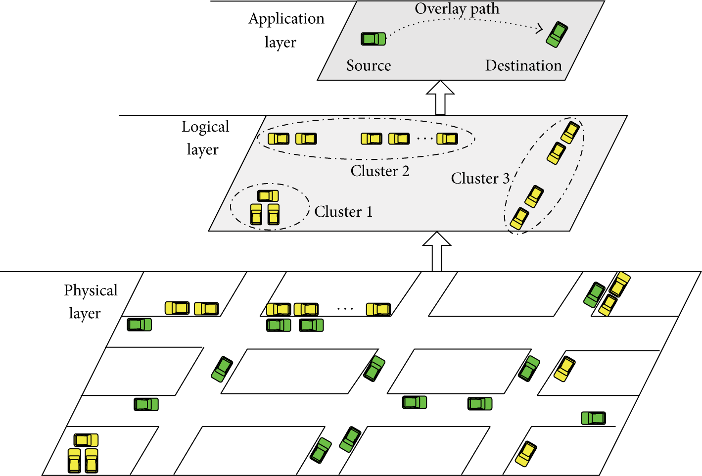
Layered architecture.
(1) Physical Layer. The physical layer is the vehicular ad hoc network, in which moving vehicles or parked vehicles communicate with each other through one-hop or multihop transmission.
(2) Logical Layer. The logical layer is our Parking Backbone formed by outside parked vehicles that work as both data storage units and data transmission units in the virtual infrastructure. This virtual overlay network self-organized in a distributed manner for the support of target vehicle tracking and message dissemination on top of the VANET.
(3) Application Layer. Application layer focuses on safety and comfort applications for vehicle users. In this layer, the driver can send data to a target vehicle or issue certain request from it on the driver's demand.
As shown in Figure 1, since the source vehicles depend on the proposed overlay network for destination vehicles tracking and messages transmission, how to effectively establish and maintain the overlay network is an important issue that needs to be carefully addressed. Accordingly, we suggest a novel overlay network design approach in this paper, as Parking Backbone over VANETs.
4. Design of Parking Backbone
For the idea of Parking Backbone, we first define the road cluster and then focus on the overlay network design based on road clusters.
4.1. Road Cluster
In Parking Backbone, we try to group all parked vehicles both on one road and off the road into a road cluster. It is viable, even though some parked vehicles are isolated from each other or belong to different partially distributed groups. The reason is that, for the on-street vehicles, the width of a parking space is about 5 meters. Since the transmission range of the vehicle is about 250 meters and the off-peak occupancy ratio averages almost 80%, for a parked vehicle in a parking lot, the probability of finding another parked vehicle is very high. For the off-street parked vehicles, some vehicles will drive in and out of the parking lots where they parked in. These moving vehicles bridge the disconnection in the store-carry-forward way and help to maintain the whole road cluster.
A typical road cluster is as shown in Figure 2, which has two cluster heads
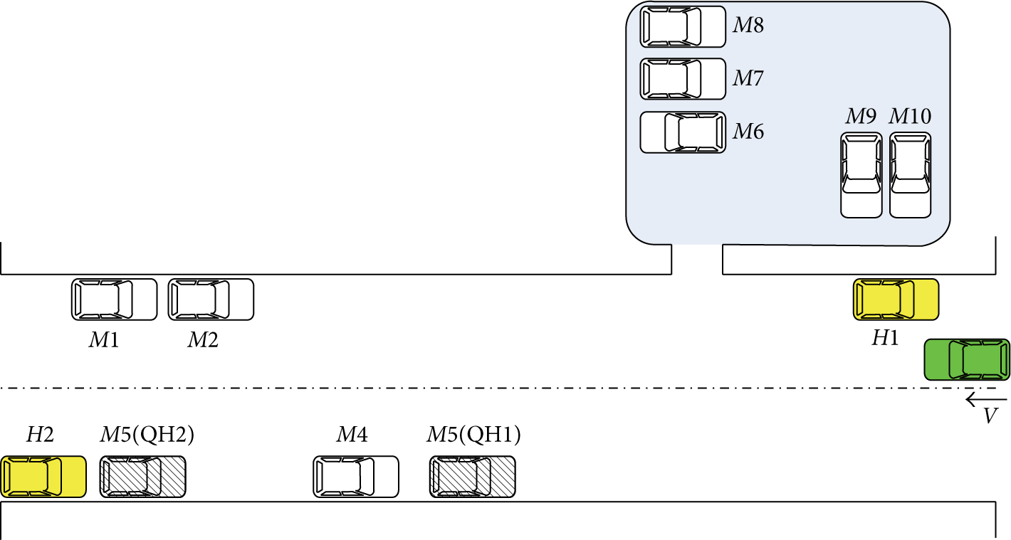
A typical road cluster.
4.2. Overlay Network Construction
Instead of deploying RSUs, we try to construct a Parking Backbone overlay network on top of the physical VANETs, to achieve target vehicle tracking and efficient data delivery. Concretely, the virtual overlay network construction process has the following steps.
Each road cluster starts a neighbor discovery process using a simple mechanism with the help of intermediate vehicles. For instance, a cluster head of road cluster J periodically broadcasts a To organize road clusters into a Parking Backbone, we let each road cluster connect with all its neighbor clusters. Thus, each road cluster becomes a member node and each connection between two neighbor cluster members becomes a virtual link of the overlay network. Moreover, each member node maintains the topology map of the virtual network. This could be realized with the help of intermediate vehicles; for example, each member node broadcasts its location to other member nodes over the network. This process is similar to link-state broadcast [13]. Figure 3 illustrates the concept of our overlay network.
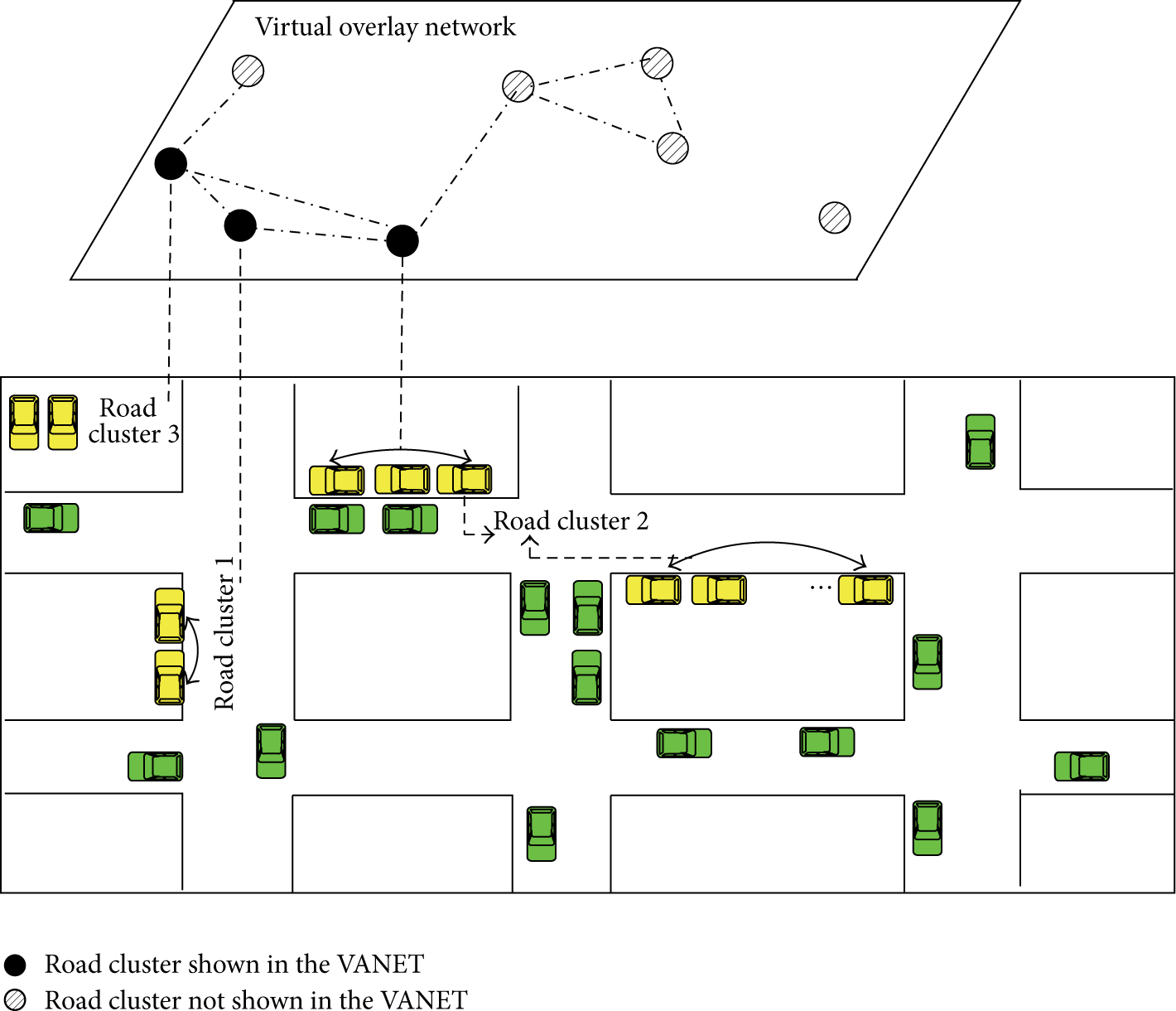
The virtual overlay network.
As a survey [14] that explores on-street parking in cities points out, the utilization of the parking spaces is quite stable. The occupancy ratio, which is defined as occupied space-hour/available space-hour, averages 93% throughout one day. Even off-peak occupancy ratio averages almost 80%. In addition, the authors in [15] spatially describe the detailed parking distribution in Montreal city in Canada at 12:00 and 22:00, respectively, which demonstrates the substantive vehicle sources in all hours of one day. Consequently, we conclude that, guaranteed by the high utilization and wide coverage of outside parking, establishing a stable Parking Backbone is feasible.
The proposed overlay network has the following distinct advantages. First, the virtual topology can remain static even though the underlying physical topology is changing rapidly. Thus, we can shield the complicated implementation details of the underlying physical network and tackle the message transmission issue on top of the VANETs. Second, as member nodes of the overlay network, each road cluster can be assigned a static network address like a static IP address on the Internet. A routing protocol similar to the link-state routing can then be designed for efficient data delivery over the overlay network. The other advantage is message bundling. That is, messages with the same destination can be bundled into one message, with the aim of reducing processing overhead and bandwidth consumption.
A real world urban parking utilization report [16] gives a parking study conducted in old town Alexandria, from which we obtain the density of roadside parking reaches one roadside parked vehicle per 7.58 meter road lengths. Similarly, [17, 18] provide the roadside parking situation and the road construction in Singapore, respectively, from which we acquire that the density of roadside parked vehicles in Singapore reaches one roadside parked vehicle every 52.63 meters in average, as shown in Table 1. Due to the high density of parked vehicle in the two cities, we deduce that most of roadside parked vehicles can mutually connect in the city. Thus, our Parking Backbone achieves good network connectivity.
On-street parking in two cities.

5. Vehicle Location Prediction
In this section, we first present the idea of vehicle tracking and locating. Second, how to establish vehicular mobility models to achieve vehicle tracking is described. Third, we focus on the method to track a target vehicle. Finally, the algorithm to locate the target vehicle based on its mobility model is discussed.
5.1. Overview of Vehicle Tracking and Locating
To transmit the message to a mobile target object, some previous works try to use flooding or large-scale multicopy delivery. However, due to their large traffic overhead and high energy consumption in message transmission, these algorithms are impractical to be applied in large networks. So, if we can track the location of the target vehicle, the message can then be transmitted more efficiently. However, due to the highly moving speed, tracking and preciously locating a moving vehicle are a tough work, especially in no fixed infrastructure based network. Thus, a new method to track and locate a vehicle is extremely needed.
Here we explain how to track and locate a specific vehicle by giving a simple example. In Figure 4, a moving vehicle S needs to send a message P to a target vehicle D, in which steps of a specific vehicle tracking and location acquisition are concisely described.

A typical destination vehicle tracking and location acquisition.
Message transfer: when a driver issues a message P, the source vehicle transmits P to the road cluster it is about to encounter (named
Query: if no information about vehicle D is found in the head of
Echo: Parking Backbone members are checked on the destination vehicle's mobility model during the dissemination of the query message, with which some road clusters that contain the mobility model of D are found. Each of these road clusters then sends an echo message back to
Location prediction: the road cluster D which is about to pass by (named road cluster
Transmit again: message P is sent to
Receive: P is transmitted to the destination vehicle D as soon as D encounters
There are several challenges in the implementation of this idea. First, since our target vehicle tracking and locating lie in explicit vehicular mobility model, how to describe and model vehicle's daily moving is the key content. Second, efficient vehicle location tracking is necessary. Finally, precise location prediction should be considered.
5.2. Establishing Mobility Model
Table 2 lists some vehicles tightly related to our life. Buses support public transportation on some predefined routines. Taxies provide business services for passengers. Ambulances and other special vehicles respond to emergency calling, while personal vehicles are controlled by individual drivers and follow their respective social activities. Since different vehicles move in different ways, in the following, we introduce how to build mobility models for main types of vehicles.
Vehicles and regular features.

5.2.1. For Personal Vehicle
Many researches validate that personal vehicles have regular mobility. Two to four main locations cover more than 70% of the overall trips of a personal vehicle. Some previous mobility prediction schemes try to establish the mobility pattern of a personal vehicle by recording its node-specific trajectories from GPS data. Since a vehicle will encounter a road cluster when entering a road where parking is permitted, we inspire to describe the movement of the personal vehicle by recording the road clusters it passes by. For example, a series of trips taken by the driver can be kept as records in Table 3, where “No.” represents the ID of the road cluster that the driver encountered in history, while the meeting time with each road cluster is separated into day (Mon., Tues., Wed., Thurs., Fri., Sat., Sun.) and the concrete time on that day. During movement, whenever a driver meets a road cluster, the onboard device will log the encounter time and record the ID of the road cluster.
Trip cluster record.

We also find from Table 3 that, unlike usual, the driver took a different trip on Tuesday. This is possible for that he might go to other places such as hospital before going to workplace on that day. Moreover, in order to shorten data size, the onboard device merges the same trip trajectories by letting both the mean time value and the variance indicate the encounter time fluctuation of these trajectories. A simplified mobility model of Table 3 is shown in Table 4. With the mobility model, home road cluster and destination road cluster for each vehicle are defined in Table 3.
Simplified trip cluster record.

5.2.2. Home Road Cluster
The road cluster the driver starts with and goes back to after a whole day's driving (like road cluster 2 in Table 4).
5.2.3. Destination Road Cluster
If the encounter time interval between a road cluster and its next road cluster is larger than a threshold μ, this road cluster is a destination road cluster for this vehicle. Generally, the vehicle stays at its destination road cluster for a long time.
When a moving vehicle shows an up-to-date trip, the vehicle updates its previous mobility model and informs the new model to all its encountered road clusters timely. Consequently, road clusters always keep the latest mobility model of vehicles.
5.2.4. For Taxi
Huang et al. [19] prove that taxi mobility not only has regular microscopic behavior, but also shows macroscopic features. A taxi located in a certain area prefers to go to another area as the destination of a travel. Since it is very difficult to capture the microscopic regularity of the taxi, here we try to find the highly frequented locations of the taxi, in order to capture the taxi's macroscopic movement. For a taxi m, suppose the probability of encounter road cluster i while driving is expressed as

5.2.5. For Bus
Generally, buses have predefined trips. The schedule of the bus, including the first bus, the last bus, and the frequency of the bus service, is available from predefined routines. Since electric map is widely deployed in buses nowadays, the road clusters that a bus will meet while moving can be obtained easily. Accordingly, a bus can estimate the meeting time with each road cluster on its trip according to its start time, its average moving speed, and the distance from the start point to each road cluster calculated using the electric map. However, since the movement of the bus is seriously affected by traffic conditions (e.g., traffic jam), using the bus schedule to predict bus movement is not so accurate. Thus, instead of utilizing bus schedule, we use the same method as we used with personal vehicle, to predict bus movement.
5.3. Mobility Model Diffusion and Location Tracking
When a moving vehicle meets a cluster head, it will report its mobility model. By this means, vehicle mobility models in the urban area are recorded after a time period. When a source vehicle S issues a message P to a vehicle D, since it has no knowledge of the location of D, it should firstly track the target vehicle. To track a specific vehicle, the cluster head of It checks whether D is now within the same road cluster with itself. If so, it initiates internal communication to distribute P to D directly. Otherwise, it checks whether it has the mobility model of D, if so, indicating that D can be tracked immediately. If it does not have the mobility model of D, a query message that contains the encounter time between S and

The weighted connected graph.
5.4. Location Prediction
After obtaining the mobility model of the destination vehicle, the location of the destination vehicle should be determined, for efficient message transmission. In the following, we propose a simple algorithm, as shown in Algorithm 1, to effectively predict the next location of the destination vehicle.
(1) match(α, day value in mobility model of D) (2) (3) (4) S·add(1); (5) (6) (7) (8) S·add( (9) (10) S·add(m); (11) (12) (13) (14) (15) S·add(m); (16) (17) S·add( (18) S·add(m); (19) (20) (21) (22)
The main idea of the algorithm is tried to find the road cluster the destination vehicle is currently parked in or about to encounter by comparing the encounter time value provided in the query message with the history time records in mobility model of the destination vehicle. Note that
6. Message Dissemination
To disseminate messages to destination vehicles efficiently, we abstract the whole overlay network as a weighted connected graph
In order to calculate 
We explain our message dissemination from two modes. In the straightway mode, messages are routed along the maximum spanning tree to their destination road clusters. The maximum spanning tree could be easily acquired at each member node through the classic Kruskal's algorithm. In the intersection mode, if two adjacent road clusters on the optimal path cannot connect with each other directly, we must check if there is a moving vehicle available to help forward through intersections. Among all the moving vehicles in the intersection, the vehicle which is moving in the message-forwarding direction is the optimal message carrier. If no optimal vehicle exists, a vehicle that is moving towards the reverse direction of the message-forwarding is selected as the message carrier, as shown in Figure 6. If there is no vehicle available to forward ahead, messages should be stored until an available vehicle appears. Overall, in our method, messages are tried to be forwarded with the minimum message transmission delay and message-loss rate to their destinations.

Select the next vehicle in the intersection.
7. Performance Evaluation
In this section, we investigate realistic parking and traffic profile in real urban environments. We also evaluate the performance of Parking Backbone in NS-2.33.
7.1. Survey
We performed a six-week survey on an ordinary urban area of Chengdu, a city in China, for collecting realistic parking and traffic profile. As shown in Figure 7, we extract a real street map with the range of

Road topology in simulation.
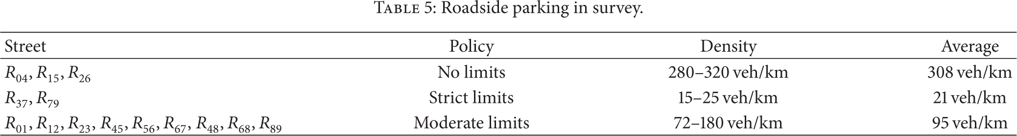
During the survey, we investigated the traffic and roadside parking statistics at 16:00, 18:00, and 22:00 of every Tuesday, Thursday, and Saturday. We counted the vehicles parked along each street within 5 meters and skipped those parked in the middle of obstacles or too far from the roads. To 33 on-street parking lots, only fringed vehicles along road direction were calculated. As show in Table 5, there are three classes of streets with different parking limits. The first class permits free parking at roadside, as
Roadside parking in survey.
7.2. Simulation Environment
In this section, simulations are conducted in NS-2.33. We use the open source software VanetMobiSim-1.1 [20] to generate realistic urban mobility traces. The default number of vehicles is set to 200, and their radio range is set to 250 m. The average speed ranges from 40 to 80 kilometers per hour. The MAC protocol is 2 Mbps 802.11. In the simulation, parked vehicle nodes are located on random positions of each street or each off-street parking lot. For parked vehicles located on street, they follow the density collected in Table 5. The average parking time is 41.40 minutes with a standard deviation of 27.17, which is provided in [21]. Each vehicle generates a new request
To compare our scheme with other VANET routing protocols, we simulated two protocols: CAN DELIVER [4] and RBVT [8]. We modified the design of RBVT to make each intermediate vehicle carry the message for a specific time (default of 10 s) if it finds that the next link is broken. To simulate the performance of CAN DELIVER, four RSUs were deployed uniformly across the map. The transmission range of RSU is set to 250 m. The metrics used for comparison are message delivery ratio, message delivery delay, and average vehicle traffic, which is the average traffic generated, received, and forwarded by a vehicle during the simulation time.
7.3. Results under Default Parameters
In Figure 8, we compare the message delivery ratio in Parking Backbone and the other two protocols under default parameters. We can see that Parking Backbone achieves higher message delivery ratio than CAN DELIVER and RBVT. This is mainly because, based on stable and large amount of roadside parking and off-street parking for message delivery, Parking Backbone has stable contact opportunities and high-quality contacts with parked vehicle. On the other hand, since the number of RSUs is limited in CAN DELIVER, the distance of the nearest RSU to a vehicle is long. Hence, the opportunity to send a message to the nearest RSU is small. RBVT has the lowest delivery ratio since it sends messages only when a connected path is available.

Message delivery ratio under default parameters.
7.4. Varying the Number of Vehicles
We study the effect of varying the number of vehicles on the performance of the three schemes. Figure 9(a) shows that the message delivery ratio of our scheme is higher than those of the other two protocols. With the increase of the number of vehicles, the delivery ratio of CAN DELIVER and RBVT increases steadily. The reason is that more vehicles provide better possibilities and more contact opportunities to select a relay vehicle to delivery messages in dense traffic. However, since Parking Backbone mainly is based on stable roadside parking and on-street parking for message transmission, it has stable contact opportunities and high-quality contacts, and slightly affectted by vehicular number change. In Figure 9(b), the message delivery delay of CAN DELIVER is less than RBVT in dense conditions, which proves that routing message via RSUs is faster in such cases. Figure 9(c) shows that the average vehicle traffic of CAN DELIVER and RBVT becomes high when the number of vehicles increases due to redundancy, which produces high traffic.
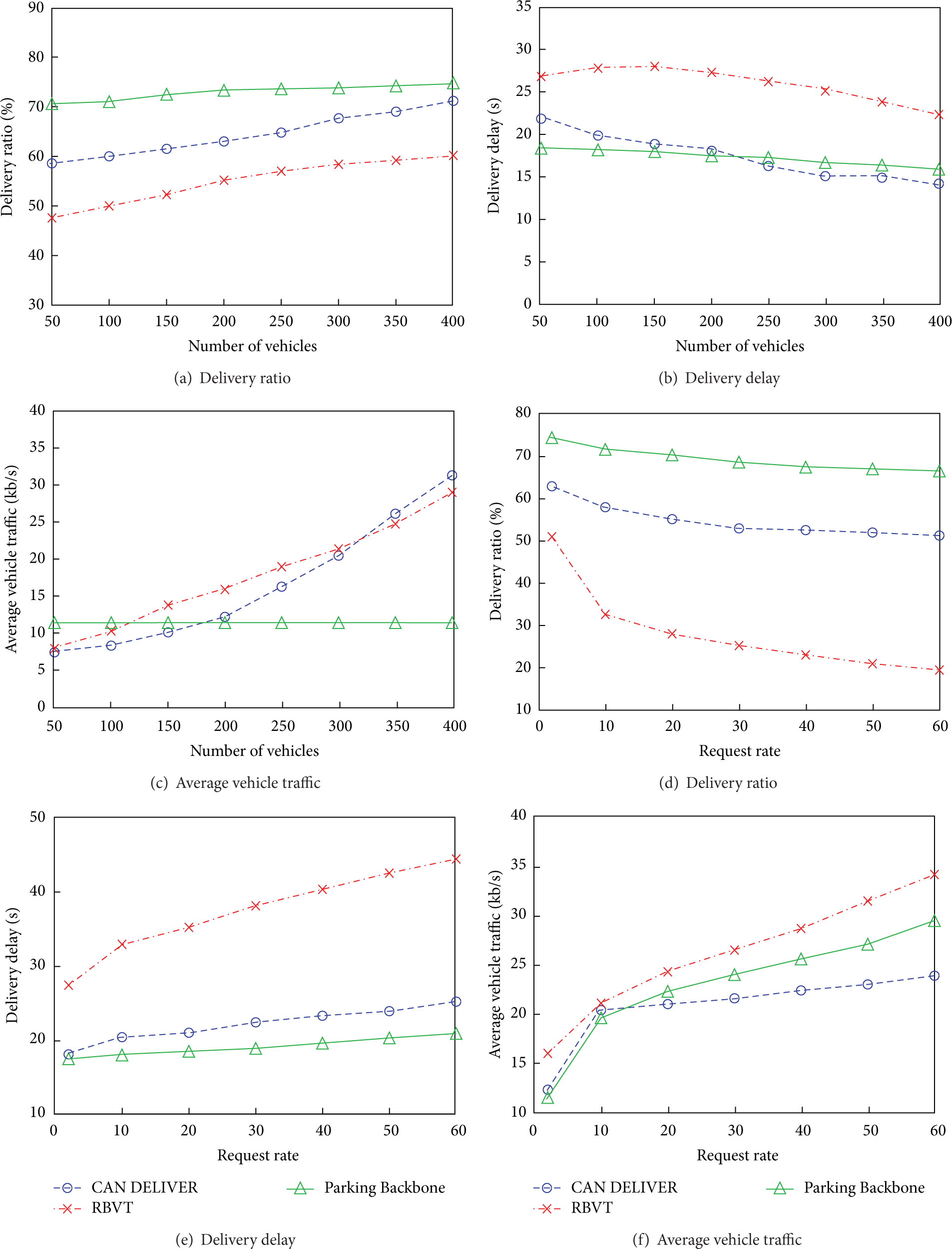
Impact of number of vehicles and request rate.
7.5. Varying the Request Rate
In this section, we discuss the performance of the three schemes when varying the request rate
7.6. Varying the Number of RSUs
In this section, we uniformly deploy 1, 4, 10, and 20 RSUs in the simulation area and then compare the performance of CAN DELIVER with both our scheme and RBVT. The results are shown in Figures 10(a)–10(d). In Figure 10(a), the delivery ratio of our protocol is higher than CAN DELIVER with 4 RSUs but lower than the latter with 10 and 20 RSUs. This is reasonable since when more RSUs are deployed, a vehicle to its nearest RSU will be closer. Hence, the opportunity to send a message to the nearest RSU will increase. Figure 10(b) depicts that the message delivery ratio of CAN DELIVER increases as the number of RSUs increases. The reason is the same as described in Figure 10(a). We also notice that when the number of RSUs is large enough such that the whole network is well covered, the delivery ratio will significantly increase and the average message delivery delay will largely decrease (see Figure 10(c)).

Parking Backbone, RBVT, and CAN DELIVER for different number of RSUs versus number of vehicles.
8. Conclusion
This paper proposes Parking Backbone, which lets extensive parked vehicles support vehicle tracking and message dissemination as roadside units. In this paper, we first investigate the design of Parking Backbone. Then, we establish mobility model for different vehicles and propose algorithm to predict the rough location of the destination vehicle. Finally, effective message delivery scheme is discussed. The evaluation of Parking Backbone confirms its effectiveness as compared to recent routing protocols for VANETs.
Footnotes
Conflict of Interests
The authors declare that there is no conflict of interests regarding the publication of this paper.
Acknowledgment
This work was supported by the National Natural Science Foundation of China (Grant nos. 61103227, 61103226, 61272526, 61170256, 61173172, 61173171, and 61370204).