
Abstract
We analyze the response of passive mixing to shock wave in a density-stratified supersonic shear layer by means of direct numerical simulation with a high-order hybrid compact-WENO scheme. The coexistence gradients of density and pressure have a complex influence on generation of baroclinic vorticity, depending on the gradient directions. The growth rate of mixing layer thickness is increased by the presence of shock wave, but the mixing layer thickness is not always increased. The passive mixing can be enhanced in a thickened shear layer by the incident shock wave if the homodromous vortexes are induced by the baroclinic torque. The mixing efficiency is also enhanced by increasing the density difference of two streams. The present study can be helpful to take measures to strengthen the mixing process in supersonic shear flows.
1. Introduction
Acquirement of fast and highly efficient mixing is a very challenging problem in supersonic flows. Shear layer flows are widely applied in scramjet to increase the mixing of two supersonic streams. Moreover, it has been found that the introduction of shock wave into a supersonic shear layer flow may enhance the mixing performance [1–3]. Due to the incident shock wave, the mixing process is much changed with the compression of vortexes and the generation of baroclinic vorticity. Some researchers have studied the interactions between shock wave and vortexes to explain the mechanisms of mixing enhancement [4–6]. And it has been shown that the complex shock wave refraction contributes to the mixing increase [7]. Hermanson and Cetegen [8] have experimentally studied shock-induced mixing of nonhomogeneous density turbulent jets and indicated that the reversal of the density ratio between the jet and the surroundings, and the consequent change in the sign of baroclinic vorticity, does not yield similar effects in terms of flow structure or mixing enhancement. However, passive mixing induced by shock wave in density-stratified shear flows has not been well studied.
Therefore, in the present paper, the shocked mixing layer flows are numerically simulated considering the effects of density stratification of two streams. The thickness of mixing layer and the mixing efficiency are then carefully compared. The physics of mixing enhancement by the oblique shock wave is then discussed.
2. Numerical Methods
The shocked density-stratified supersonic mixing layers are simulated by means of direct numerical simulation. The three-dimensional conserved compressible Navier-Stokes equations, together with a passive scalar conserved equation, are numerically solved:
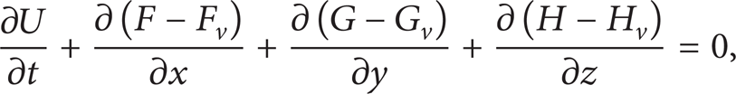
where
E is the total energy per unit mass, which is related by

C is the passive scalar. The numerical flux is obtained by a fifth-order compact-WENO hybrid scheme [9] for the convective terms and a sixth-order compact difference scheme for the viscous terms. The temporal integration is performed using a third-order Runge-Kutta algorithm.
For the order of exciting the flow instability, a specified tanh-type velocity profile coupled with random disturbances is imposed as the inlet boundary condition. The nonreflective boundary condition is specified at the bottom transverse boundary. The oblique shock wave equation is used at the upper transverse boundary to introduce incident shock wave. The periodicity boundary conditions are used in the spanwise direction. The present numerical methods are carefully validated by exactly simulating a free shear layer flow, which was experimentally measured by Goebel et al. [10]. The details of numerical procedures can be referred to in [7].
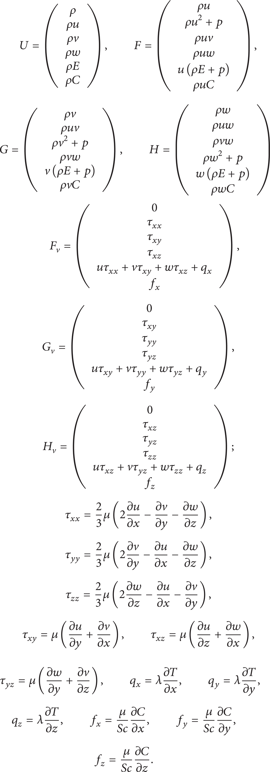
The parameters of density-stratified mixing layer and shock wave for the present study are given in Table 1. The convection Mach numbers, Mc, for three cases are kept constantly, taken as 0.4; the strength of shock wave, represented by Δp/p1, is identical, taken as 0.656. The introduction position of shock wave is at x = 0.7 m from the upside of stream 1. The inflow static pressures of both two streams are taken as 46 kPa. The velocity ratio of two streams is equal to 0.68.
Mixing layer and shock wave parameters for the simulations.
3. Results and Discussion
3.1. Variations of Vorticity
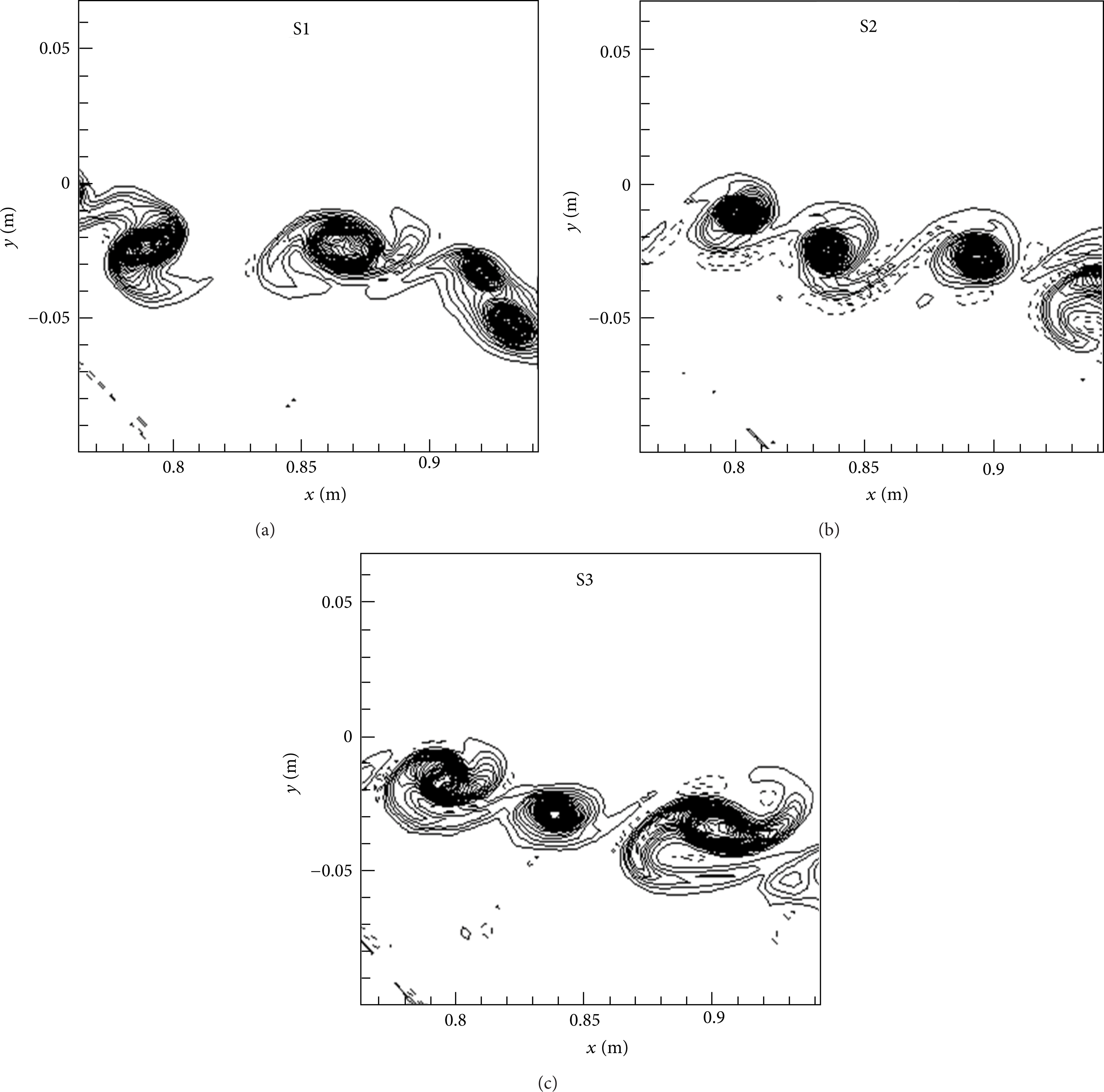
We analyze how the shock wave changes the developing of mixing layer by presenting the instantaneous isocontours of spanwise component of vorticity, as shown in Figure 1.

Isocontour of spanwise component of vorticity in shear layers for different density ratios.
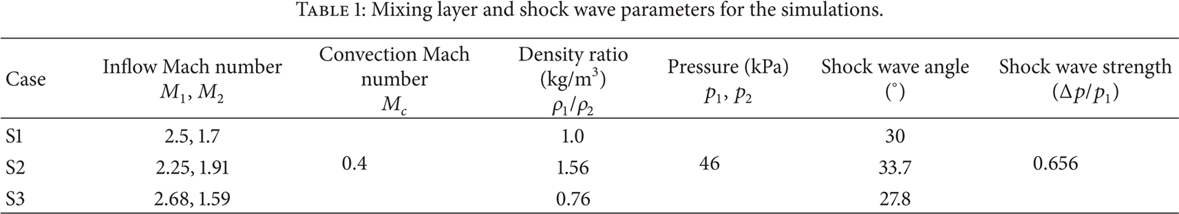
The mixing layer is inclined by the action of incident shock wave and the deflection angle tends to be the same as the strength of shock wave is identical for the three cases. The evolutions and macroscales of mixing layer are overall similar, because the developing of shear layers is mainly determined by the velocity difference of two streams, and the velocity difference in the present cases is taken as the same. Partially enlarged details of vortexes are shown in Figure 2. The solid lines represent the negative vorticity, while the dashed lines represent the positive. The vorticity of vortexes is mainly negative for Case S1. The positive vorticity exists on the edge of vortexes for Cases S2 and S3. In addition, the positive vortices locate differently relative to the vortex core even for Cases S2 and S3. For Case S2, the positive vorticity locates in bottom left or right of braid regions of vortex core. However, for Case S3, the positive vorticity locates in top right or left of braid regions of vortex core.
Isolines of spanwise component of vorticity in shear layers for different density ratios.
The generation of positive vorticity is due to the generation of positive baroclinic vorticity during the interaction of shock wave with density nonhomogeneity mixing layer. For Cases 2 and 3, the fluid density of two streams is different. Therefore, the density gradients exist in the braid region of vortexes, and its direction does not parallel that of pressure gradient. However, there exists almost zero density gradient in vortex braid region due to density homogeneity for Case 1, and hence no baroclinic vorticity generates. This will be explained in detail as below.
The generation of baroclinic vorticity in the saddle point region in the scalar field is sketched in Figure 3. For Case S2, the density gradient at the right hand of saddle point directs at bottom right, but the pressure gradient directs at bottom left towards the saddle point. They are almost orthogonal to each other. According to the right-hand rule, the vorticity generated by the baroclinic torque is clockwise (it is defined as the negative vorticity in this paper) and has the same rotation direction as the vorticity of mixing layer. To the contrary, at the left side of saddle point, the pressure gradient does but the density gradient does not change the direction. Therefore, the induced vorticity is counter-clockwise, which is positive in the present study. The vortices with positive vorticity departure from the saddle point under the function of strain rate revolve around the left vortex core at the right side. For Case S3, the direction of density gradient is reverse compared with Case S2. Hence, the positive vorticity is generated at the right side of saddle point. The vortices are acted by the strain rate of fluid and encircle the right vortex core at the left side. From the above analyses, whenever the density ratio is larger or smaller than unity, the baroclinic vorticity is always tending to entrain the light fluid into the vortex core but expel the heavy fluid outside the vortex.

Sketch of generation of baroclinic vorticity in saddle point regions of scalar field.
3.2. Variations of Thickness of Mixing Layer
We then explain the variations of thickness of shocked mixing layer for different density ratios as shown in Figure 4. The thickness of mixing layer, δ C , is defined as the distance across a shear layer from two points where the passive scalar C has essentially (for instance 99%) reached the scalar value of free stream, which equals 1 at the high-speed stream side and equals 0 at the low-speed stream side.

Variations of thickness of mixing layers for different density ratios.
The shocked mixing layer is compressed at the acting position of shock wave and the mixing layer thickness is then rapidly decreased there. The growth rate of mixing layer thickness is enlarged in the meanwhile, but it depends on the density ratio. For Case S3, the growth rate of shocked mixing layer is increased the fastest, and hence the mixing layer thickness exceeds that without shock wave soon and finally increases 6% at the outlet boundary. For Case S2, the thickness growth rate slightly increases but does not recover to the level without shock wave. Although the growth rate of shocked mixing layer is increased for Case 2, the thickness of mixing layer is the smallest. The variation for Case S1 is in between. In a conclusion, the change of density ratio has an obvious influence on the development of shocked mixing layer, including the macro thickness scale and its growth rate.
Both the baroclinic torque and volumetric expansion terms influence the vorticity generation in the shocked mixing layer. The change of fluid density ratio can lead to a variation of contributions from the baroclinic and volumetric expansion effects, as shown in

Figure 5 shows isolines of baroclinic torque, (∇ρ × ∇p)/ρ2, and volumetric expansion terms,

Isolines of baroclinic torque and volumetric expansion terms for different density ratios. (a) and (b): Case S1; (c) and (d): Case S2; (e) and (f): Case S3. (a), (c), and (e): baroclinic torque; (b), (d), and (f): volumetric expansion. The solid lines represent the positive values and the dashed ones represent the negative. The contour is the spanwise component of vorticity.
For Case S1, when the vortex interacts with the shock wave, the volumetric expansion term dominates the variation of mixing layer vortex vorticity, and the baroclinic torque term only functions inside the vortex relatively weakly. For Case S2, in the regions A and B where the shock wave interacts with a vortex edge, the density gradient intersects with the pressure gradient induced by the shock wave. The consequence of the intersecting is the generation of large baroclinic torque in the positive direction. With the function of baroclinic torque, the vorticity is then generated with an opposite rotation direction to the main vorticity of mixing layer, denoting the positive direction. The fluid elements are compressed by the shock wave in the regions, and hence the volumetric expansion is also in the positive direction, but twice smaller than the baroclinic torque in magnitude. Therefore, the positive vorticity generated by the baroclinic torque mainly dominates in the regions; that is, it may weaken the vorticity strength of vortexes of mixing layer. However, the function of baroclinic torque is not obvious inside the main vortex (we call the vortex generated by shear of two streams the main vortex), and the vorticity is increased due to the compression of shock wave. Because of positive baroclinic vorticity or weakened negative vorticity on the edge of main vortexes of mixing layer, the entrainment of free fluid is attenuated. Therefore, reviewed in Figure 4, the thickness growth rate of shocked mixing layer is increased lightly, and the mixing layer thickness grows slowly compared with Case S1.
For Case S3, very large baroclinic torque exists in the regions of A and B where the shock wave interacts with the vortex edge. However, the torque changes its direction due to the change of density gradient direction. Therefore, the vorticity is generated with the same rotation direction as that of the main vortex of mixing layer. The fluid elements in the regions are compressed by the shock wave, and the volumetric expansion is in the positive direction. Under the double action of baroclinic torque and volumetric compression, the generated negative baroclinic vorticity strengthens the vorticity on the edge of main vortexes of mixing layer, and hence the entrainment of free fluid is enhanced. Inside the main vortex, the volumetric expansion plays a leading role, and therefore the vorticity is increased due to the shock wave compression. Compared with Case S1, the growth rate is increased significantly in the shocked mixing layer in Case S3. Therefore, the mixing layer grows the fastest and its thickness finally exceeds that of unshocked mixing layer.
3.3. Variations of Mixing Efficiency
The definition of mixing efficiency used in the present study is

where variables with overbars stand for the time-averaged quantities. The above parameter considers the mixing effectiveness of entrained fluid in the mixing layer. Based on our definition, the mixing is the best if the passive scalar C is equal to 0.5 and the mixing efficiency is one, whereas the mixing is the worst if the passive scalar C is equal to one or zero and the mixing efficiency is zero.
We then show the mixing efficiency for three cases in Figure 6. For Cases S1 and S2, the mixing efficiency of shocked mixing layer hardly changes, though the growth rate of thickness is increased in Case S2. Only for Case S3, the mixing efficiency increases by the action of shock wave. It is concluded that the density ratio has complex effects on increasing the growth rate of the mixing layer thickness, while different density ratios have not very strong effects on enhancing mixing efficiency.

Mixing efficiency of shocked mixing layer for different density ratios.
The mixing efficiency in the shear layers is mainly determined by the entertainment of two streams. Further, the entertainment between the two parallel streams is realized by the flow shear because of velocity difference. In the present study, the velocity difference is fixed, but the density ratio is changed for two streams. Therefore, the mixing efficiency of the present cases will not be different from each other significantly. However, the observed differences of mixing efficiency among three cases are mainly induced by the change of vorticity in the shear layer, which hence influence the entertainment of the outer free fluid. In the vorticity field, the density difference leads to a density gradient and hence induces the baroclinic vorticity. During the interaction of oblique shock wave and mixing layer, the pressure gradient accompanying with the oblique shock wave can be nonorthogonal or orthogonal to the density gradient because of density difference of two streams. The baroclinic vorticity will be generated, which can contribute to the increase or decrease of vorticity of shear vortex. For the density ratio equal to unity, the baroclinic terms hardly have the extra generation of vorticity. Therefore, for this case the mixing efficiency is not increased by means of oblique shock wave. Only the mixing is enhanced in Case 3, because the baroclinic vorticity strengthened the vortex and then its entertainment of free fluid. In conclusion, for the shocked shear layer flows, the mixing can be enlarged if the baroclinic vorticity can increase the entertainment through the increase of the vorticity strength of shear vortexes.
4. Conclusions
The effects of density stratification on mixing enhancements by an oblique shock wave were studied by means of direct numerical simulation. The vortices, mixing layer thickness, and mixing efficiency were compared for different density ratios in supersonic shear layers.
The passive mixing properties of supersonic shocked shear layer flows strongly relate to the density nonhomogeneity. The complicated effects of shock wave on the vortex evolution occur, depending on the competition of the baroclinic torque over the flow shear.
With an introduction of pressure gradient by an oblique shock wave, a positive density gradient induced by the density stratification may degenerate the vorticity due to a positive baroclinic torque and hence decrease the spatial scale of vortexes in the developing mixing layer, while a reverse one can increase the vortex strength. The developing of vortexes influences the growth rate of mixing layer thickness. The growth rate of thickness in the shocked mixing layer is faster for smaller density ratios. However, the mixing efficiency has no significant change by the shock wave if the density of two streams approaches to each other.
Conflict of Interests
The authors declare that there is no conflict of interests regarding the publication of this paper.
Footnotes
Acknowledgment
The research work is partially supported by “The Importation and Development of High-Caliber Talents Project of Beijing Municipal Institutions.”