
Abstract
Currently, the use of aluminum alloy which is light weighted is increasing. Extruded aluminum profiles are used as automobile frame parts for higher stiffness and light weight. However, few studies have been performed on die forming technology of extruded materials which productivity can be much increased with. In this study, die forming processes with precision dies have been designed to manufacture automobile control arm and subframe parts using aluminum extruded profiles. Computer aided analyses have been conducted for the designed processes by the commercial FEM code, DEFORM-3D. From the results of the computational analysis, process planning and forming analysis will be completed by using the extruded profiles. And then, forming dies for each process were designed and pilot products of subframe parts and control arms were manufactured by the verified forming process. In addition, some of the important features of design parameters in the die forming were investigated.
1. Introduction
The necessities for light weight design as well as reducing fuel consumption are greatly increasing as environment-friendly and high efficiency car technology is required in these days. To make efforts to achieve the goal of emission control, light weight metals such as aluminum alloys are now replacing steel products and many researchers and automobile companies put the technology of light weight metals to practical use.
In particular, many applications and studies have been widely developed with hollow extruded aluminum profiles using various forming methods such as bending and stretch bending. However, few studies have been performed on die forming technology of extruded materials which productivity can be much increased with. Figure 1 shows schematic drawing of die forming for the extruded profile.

Schematic drawing of die forming for the extruded profile.
The part after the die forming can be used as a preform in hydroforming and can be welded or assembled for light weight automobile parts. The concept is shown in Figure 2.
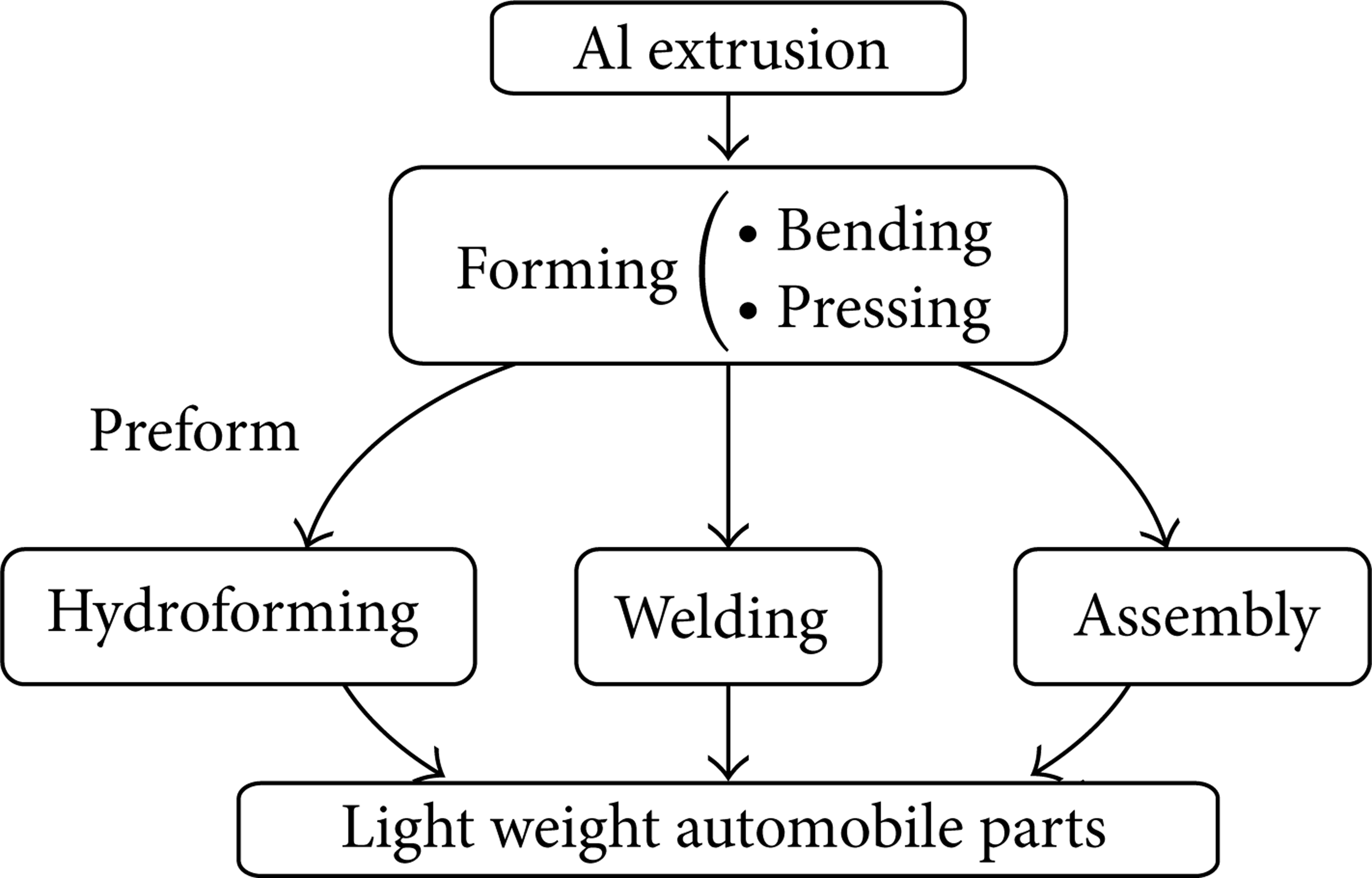
Schematic process of manufacturing light weight automobile parts.
While a lot of progress has been made in forming of square-sectioned profile by stretch bending [1–3] and hydroforming [4, 5], few studies have been performed on die forming technology of extruded profiles which productivity can be much increased with. For high productivity, die forming of extruded profile has been used.
The objective of this study is to design and manufacture automobile suspension and frame parts using extruded material by precision die forming. This study focuses on the possibility of application of extruded profiles on automobile parts with the die forming processes. First of all, computational analysis was performed to design process variables for manufacturing light weight automobile parts. The whole forming processes are composed of bending, trimming, and finally forming complex shape. The shape of section of the initial extruded profile was determined by inversely analyzing the whole processes.
From the results of the computational analysis, process planning and forming analysis will be completed by using the extruded profiles. Also, for experimental verification, two automotive parts were selected as pilot products. One is members of subframe parts and the other is control arm parts. These two pilot parts are to be manufactured by using the shape of forming dies which were obtained from the previous forming analysis.
2. Process Design of Forming with Extruded Aluminum Profile
To plan a forming process, features of product are considered. The forming process has been designed backwardly to simplify the shape from the deformed to undeformed shape. Firstly, the complex shape of the part is considered as formed by the die forming. Undeformed shape can be obtained as the simple shape. Considering trimming process, the untrimmed part is obtained. The bended shape has been designed to the unbended shape, the extrusion profile. The process design of forming with extruded profile is shown in Figure 3. For examples, forming processes are designed for some products such as a subframe member and a control arm.
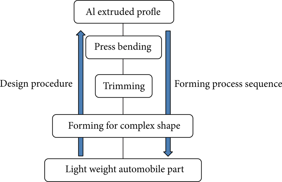
Design procedure for the forming with extruded profile.
2.1. Application to Subframe Member [1]
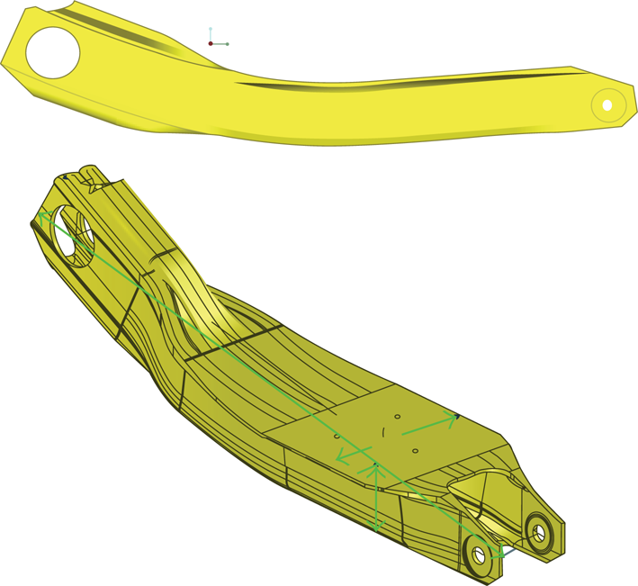
The modeled subframe member is shown in Figure 4. In Figure 4(a) the subframe is shown and the formed member is shown in Figure 4(b). The forming process of the member is designed by the following procedure. Considering pressing operation, the undeformed shape is figuratively divided and designed. The section of the undeformed shape in the successively following process is inversely identical to the initial extruded profile as shown in Figure 5. For the subframe member, the trimming process is not required. For the easy press bending design, the reference line is considered. Three-press bending process is designed as shown in Figure 6.

Modeling of the subframe member.
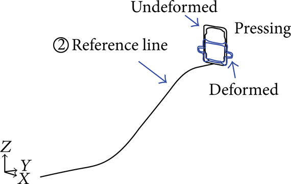
Deformed and undeformed shape of the subframe member in pressing.

Process design of press bending.
2.2. Application to Control Arm
To plan a forming process, dimensional features of the control arm (A type) are considered as shown in Figure 7. The forming process has been designed backwardly to simplify the shape from the deformed to undeformed shape. Firstly, the forming of the ends of the part, as shown in Figure 3, is considered as the side pressing. Considering trimming process, the untrimmed part is obtained. The bended shape has been designed to the unbended shape, the extrusion profile. The designed forming process is shown in Figure 8.
3D model of the control arm.

Forming process of the control arm.
3. Analysis of Forming Process for the Control Arm
FE-simulations of the designed processes have been performed to determine the detailed dimensions of the tools and workpiece. For the subframe, the detailed simulation results are given in [1]. In this paper, the FE-analysis of the forming process for the control arm has been discussed.
Finite element analysis was performed for the forming processes by DEFORM-3D [6]. The analysis uses the 1/4 model of the parts which is symmetric.
In the analysis, the material of the workpiece is elastoplastic. Faster convergence can be obtained than that case of rigid-plastic model. The springback can be calculated with the elastoplastic model.
The control arm shown in Figure 7 has some holes which have been machined after forming. On the holes, the control arm is assembled with other parts. The dimensional accuracy of the holes is important for the assembly. The formed part has to have no wrinkle, no tears, and no crack. The control arm has the limit strength that is determined based on the actual loading conditions. In the design of the control arm, the strength has been already considered. If the severe thinning occurs in forming processes, the strength of the formed control arm cannot exceed the limit value. In the FE-analysis of bending, the effective plastic strain has to be lower than that of fracture in tensile test.
3.1. Extrusion
The shape of the section without any deformation through the whole forming process was determined as the shape of the extruded profile. Aluminum 6082 was extruded with solution heat treatment and formed. The aluminum alloy was composited with 0.988 (wt%) Si, 0.55 (wt%) Mg, and 0.3 (wt%) Cu. The aluminum alloy has proper ability for extrusion with the required mechanical properties. The strain-stress curves are shown in Figure 9. The true stress and true strain relationship is curve “a” of the Al6082T6 and “b” of the Al6082F has been obtained from the extruded material with solution heat treatment.

Stress-strain relations of the Al6082 materials.
3.2. Press Bending
The press bending process was adopted for the bending process as shown in Figure 8. Figure 10 shows the schematic illustration of the press bending process.

Extruded profile.
The effective strain was obtained from the simulation as 0.136 which is a very low value. Also it is found that the wrinkle is caused by the compressive stress applied below the extruded profile as shown in Figure 11(c).

Simulation of the press bending.
3.3. Bending with the Wing-Dies
In the previous result of the press bending, it was found that the wrinkle can be caused. The inside of the extruded profile cannot be supported by tools in press bending. To prevent the wrinkle, some inside constraints with dies have to be applied to the workpiece. In the conventional press bending, however, inside constrains cannot be applied to the extruded profile by using the dies. In bending a hollow-typed material like a pipe bending process, there are well-known forming technologies to prevent buckling and partial sinking such as insertion of polymer, sand, or alloys with low melting point, overlapping some linked plates, and forming with a rigid-type mandrel [7]. The bending with the wing-dies [8, 9] for the hollow-type material can be applied to forming of the extruded profile.
In this study, wrinkles were prevented by supporting the deformed part through the wing-dies which bend the pipe by self-rotating. Figure 12 [8] shows the press bending process with the wing-dies which is operated by the hydraulic cylinder.

Wing-dies for press bending [8].
The simulations were performed for the bending of the control arm using the wing-dies and the results are shown in Figure 13.

The simulation of the bending with wing-dies.
The rotating wing-dies result in a smooth operation and cause no more wrinkles. The maximum effective strain is also much more lowered as 0.0834. To make the dimension of the bent product identical to the one of the elastically recovered part, analysis of elastic recovery was performed. The boundary conditions of external forces and contacts have been removed and the node of the center has been fixed for the springback analysis. The curvature of the punch was first compensated from the results. The elastic recovery is shown in Figure 14.

Springback prediction after wing-dies bending.
3.4. Upsetting of the Upper Part
Upsetting processes of the upper part have been performed after splitting the longitudinally bent profiles into two pieces. The symmetry boundary condition of the FE-model is removed. For the forming process after the bending with wing-dies, 1/2 model of the part has been used in the analysis. By upsetting the bulged part due to the previous bending, the formed product can be precisely identical to the 3D model. The deformation of the upsetting is shown in Figure 15.
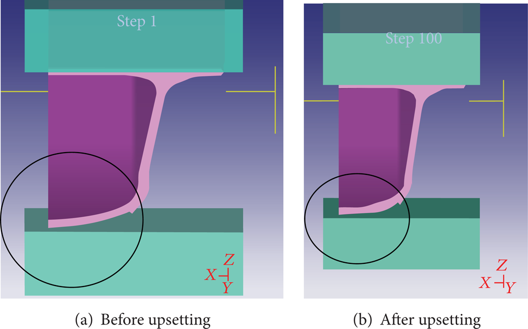
The deformation of the upsetting.
3.5. Trimming Modeling
Excessively time-killing analysis will be required for the simulation of trimming process. In this study, trimming process was realized by modifying the finite element model instead of shearing analysis. The analysis model was modified by the Boolean operation as shown in Figure 16 and the tiny increase of the strain on the sheared section was ignored.

Modeling of the trimmed product.
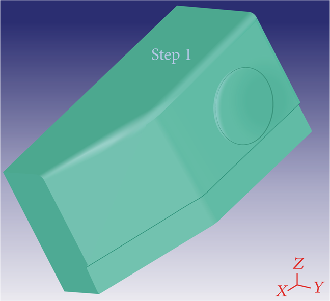
3.6. Upsetting
The upsetting process shown in Figure 8 is divided into two processes. One part is the upsetting and the other is bending of the side part as shown in Figure 17. The shape of the detailed part formed by upsetting is shown in Figure 18.

The combined forming process.

The shape of the detailed part has to be formed by upsetting.
The required shape is not able to be formed simply by a lateral upsetting. The process was planned as forming with a mandrel.
3.6.1. The 1st Stage of the Forming
The forming of the complex part is divided into two forming stages. One is that the mandrel is designed as moving forward to the product and the other is that, after exchanging the previous mandrel to the new one, the lateral forming is performed. Figure 19 shows the schematic illustration for the 1st stage. As the mandrel moves forward, the required complex shape is basically formed. As shown in Figure 19, the mandrel goes forward and the side tools are compressing and the mandrel goes forward further to the final location. In the 2nd stage, two mandrels have been used as shown in Figure 20. In the 1st stage, the inside cavity is formed for the upper mandrel in the 2nd stage.

The 1st forming stage of the complex part.

The 2nd forming stage of the complex part.
3.6.2. The 2nd Stage of the Forming
In the 2nd stage, after the previous mandrel is exchanged, the side tools compress the product as shown in Figure 20. With two stages of the forming, a more precise dimension of the product can be obtained without severe thinning.
3.7. Bending the End Part
To plan a process of forming the end part, the forming part was just simulated as shown in Figure 21. Through the repeated simulation, the shape of the punch and the plate to be cut should be determined. The analysis model was modified by the Boolean operation.

The bending of the part.
Figure 22 shows the result of the shape of the plate to be cut. In the initial design model, the wrinkle was found so that the cutting shape of the end part was modified as shown in Figure 21.

The shape design of the bending part.
In the bending the effective plastic strain of the formed part is lower than that of the fracture strain in tensile test. The thickness of formed part has a good agreement with the designed control arm.
4. Die Design and Manufacturing Pilot Products
4.1. Die Design
Using the 3-dimensional model which results from the simulation die design was performed and the die set was manufactured for the pilot products. For wing-dies bending process, the design tools are shown in Figure 23. Figure 24 shows the 3-dimensional model of the punch for bending of the end part as an example.

The wing-dies bending tools.
The punch shape of the bending part.
4.2. Manufacturing Pilot Products
Through the forming analysis, the process and the dies were designed for manufacturing control arms. Figure 25 shows the photograph of the press-formed control arms. As shown in Figure 26, the thickness distribution of formed parts has been compared with those of design and predicted values. The good agreements have been found in the comparison.
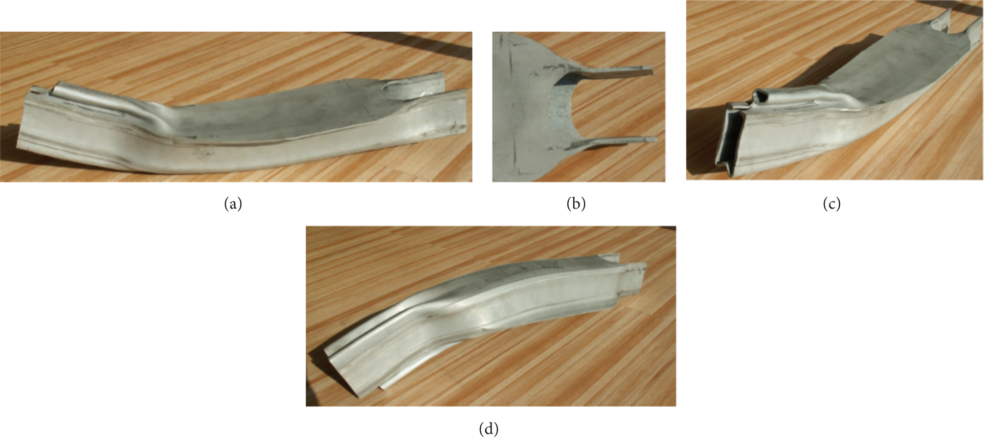
The die forming of the control arm.

The comparison of the thickness distribution of the formed control arm.
5. Conclusions
In this study, through the analysis for the aluminum control arm and subframe members which have the complex shape, the processes were planned and the results were investigated. From the results of the analysis, dimension of details of dies was successfully determined. Also using the simulated dimension of the die model in the analysis, the dies were designed. The forming method of the square-sectioned extruded profile was verified, which has been rarely investigated so far. The pilot products of the aluminum control arm were manufactured from the extruded profile and the results of the simulation agree with one of the experiments. Also it is concluded that application of extruded profiles on automobile part by the die forming process is feasible.
Conflict of Interests
The authors declare that there is no conflict of interests regarding the publication of this paper.