
Abstract
This paper presents an energy management strategy of a Li-Fe battery and supercapacitor hybrid power system to provide both high power density and energy density for mobile robots with fluctuating workloads. A two-phase power-optimization approach is proposed to exploit the high power density of supercapacitors and the high energy density of Li-Fe batteries. With our strategy, large peak power can be provided for a short time period whenever needed, while low power can be provided for very long time. A set of experiments have been conducted. The experimental results show that our strategy can effectively improve the performance of mobile robots and extend the lifetime of batteries.
1. Introduction
Robots are emerging as one of the most promising technologies in industry, national defense, and aerospace. As mobile robots often work with fluctuating workloads, an ideal power system should provide both high power density (large peak power for a short time period) and energy density (low power for a very long time). However, most mobile robots are powered by Li-Fe batteries that can only provide high energy density. A hybrid power system with Li-Fe batteries and supercapacitors provides a promising solution to solve this problem. However, in mobile robots, to fully exploit the high power density of supercapacitors and the high energy density of Li-Fe batteries in hybrid power systems, effective and efficient power management strategies need to be developed.
Several power management strategies have been proposed in the previous work. Schupbach et al. [1] propose a rule-based method to determine power distribution. With fixed rules, the method cannot adapt to changes very well. Trovao et al. [2] proposed an interacted rule-based metaheuristic optimization approach. It is used to deal with a multilevel energy management system for a multisource electric vehicle for sharing energy and power between two sources with different characteristics. This method is designed for electrical vehicle and cannot be directly applied for mobile robots. In filter-based methods [3], low-pass or high-pass filters are applied to separate low or high frequency components of power. Then supercapacitors are used to support the high frequency component. These methods cannot realize the power distribution for the large time scale power.
Fuzzy-logic-based methods [4, 5] can enhance fuel cell performance, minimize power loss, and meet the real-time power distribution requirement between batteries and supercapacitors. But these methods may shorten the lifetime of batteries that are assigned to serve high frequency pulse current. In [6, 7], power optimization algorithms for hybrid power system management have been proposed. However, these algorithms are too complex to be applied for online power control. There exist several online control strategies [8–12]. However, they are designed either for electrical vehicles or with renewable energy sources and are not suitable for mobile robots.
In this paper, based on the characteristics of mobile robots’ driving power, we propose a two-phase power management strategy to jointly optimize power density and energy density of hybrid power systems with Li-Fe batteries and supercapacitors. With our strategy, a near-optimal power distribution can be efficiently obtained so as to not only improve the performance of mobile robots but also extend the lifetime of batteries. A set of experiments have been conducted in a simulation environment. The experimental results show that the performance of mobile robots is enhanced, particularly with heavy load. and meanwhile the battery lifetime is extended.
The remainder of this paper is organized as follows. Section 2 describes background of the power hybrid system and defines the problem. Then, Section 3 briefly discusses the management strategic for hybrid power system. In Section 4, experimental results obtained through simulations. Finally, we conclude this paper in Section 5.
2. Background and Problem Statement
In this section, we first introduce the background information of Li-Fe battery (also called lithium iron phosphate (LiFePO4) battery) and supercapacitor. Then, the system architecture of a hybrid power system will be described. Finally, we will define the problem.
2.1. Li-Fe Battery and Supercapacitor
Li-Fe batteries [13] are based on lithium-ion-derived chemistry and share many advantages and disadvantages with other Lithium-ion battery chemistries. Li-Fe battery chemistry offers a longer cycle life than other lithium-ion approaches. Like nickel-based rechargeable batteries (and unlike other lithium ion batteries), Li-Fe batteries have a constant discharge voltage until they are exhausted. This allows all power to be delivered and simplifies or even eliminates voltage regulation circuitry. Li-Fe batteries are also very safe. Therefore, Li-Fe battery becomes a promising replacement for lead-acid batteries in many applications. Li-Fe batteries can provide a lot of energy but with relatively low peak power. However, large peak power may be needed in mobile robots; for example, when they need to accelerate or climb a hill. Moreover, mobile robots can regenerate energy in some cases such as breaking or going downhill. But Li-Fe batteries only have a little capability to accept the regenerative energy.
Supercapacitor [14–16] bridges the gap between conventional capacitor and rechargeable battery. It is a new technology for the storage of electrical energy. It has the highest available capacitance values per unit volume and the greatest energy density of all capacitor. And it supports up to 12,000 farads/1.2 volt, with capacitance values up to 10,000 times more than that of electrolytic capacitor. While existing supercapacitor has energy densities that are approximately 10% of a conventional battery, its power density is generally 10 to 100 times greater. Power density is defined as the product of energy density and the speed at which the energy is delivered to the load. With large power density, a power system can shorten charge/discharge periods and tolerate more charge/discharge cycles. As a supercapacitor can provide instantaneous high power and effectively store regenerative energy, it can provide an ideal power system for mobile robots by combining with Li-Fe batteries.
2.2. System Architecture and Problem Statement
In order to fully utilize the advantages of Li-Fe battery and supercapacitor and to hide the disadvantages of them, a hybrid power system is employed. The structure of a hybrid power system with Li-Fe battery and supercapacitor is shown in Figure 1. The proposed hybrid power system has a two-source structure. Li-Fe battery provides direct current to satisfy application-specific power needs. Supercapacitor is used to provide instantaneous high current and achieve energy recovery. The DC-DC converters which connect Li-Fe battery and supercapacitor with DC-BUS are used to control the power supply distribution. It allows current to be transferred in both directions. DC-DC converters often are based switching schemes driven by pulse with modulation (PWM).

The structure of a hybrid power system by Li-Fe battery and supercapacitor.
As depicted in Figure 1, the hybrid power system can not only provide power to the load, but also recycle the feedback power from load during mobile robots braking or downhill. Thus the efficiency of the energy utilization in hybrid power systems is greatly improved.
Based on the above problem analysis, we further clarify the problem as follows. In the hybrid power system, both Li-Fe battery and supercapacitor can have discharge or charge state in the process of work. The loads here are the drive motor, control circuit, and so forth. And the motor may have two kinds of working conditions. When the robot motor works at the state of electric driven motor, power will be consumed. Motor will output power when a robot is in the braking mode or downhill mode. The direction of the energy flow is decided by the working state of the power system. Bidirectional arrows indicate that energy can flow at two directions in the figure. I L , IBat, and ISC express the load current, battery power supply current, and supercapacitor power supply current through bidirectional DC-DC converter, respectively. State of charge (SoC) of Li-Fe battery and supercapacitor also is measured in this system. The PWM signals which are generated from energy management strategy are used to control bidirectional DC-DC converter for current flowing. Then, the supercapacitor can take their advantages to improve the mobile robots’ dynamic performance and extend the battery life.
3. Energy Management Strategy
In this section, an energy management strategy for the hybrid power system is proposed. Our energy management strategy consists of two steps. In the first step, we study an energy management model. In the second step, we propose a two-phase approach to improve the dynamic performance of mobile robots and extend the battery life. Our two-phase approach is summarized as follows.
In the first phase, rules of current flow are proposed to control the correct operation range of Li-Fe batteries and supercapacitors base on the working modes of mobile robots.
In the second phase, an algorithm is proposed to split the request current to Li-Fe battery and supercapacitor with appropriate current parameter assignments.
3.1. Energy Management Model
The hybrid power system with Li-Fe batteries and supercapacitors for mobile robots is shown in Figure 1. The Li-Fe battery is the main source which provides enough power requirements for a robot to work at low speed or with light load conditions, while supercapacitor is used to provide peak current and store the maximum amount of energy when the robot is in deceleration or braking. The performance of a robot can be improved with hybrid power systems. The notations used in this paper are summarized in notations section.
Supercapacitor should have the SoC level to help the Li-Fe battery overcome its performance limitations and to absorb most of energy produced by motor braking. Therefore, the planning management strategy should define a scheme to keep the supercapacitors’ SoC at an appropriate level for any request. The objective function is defined as follows:

Subject to:


Equation (2) is the fundamental equation in the proposed problem. In this equation, I L [t] means the current demand of the system and Ibat[t], Isc[t] are the power supply by Li-Fe battery and supercapacitor at time t, individually. Taking into account the characteristics of each power source, the current constraints for these power sources are given by (3) and (4). The current assignment parameters for Li-Fe battery and supercapacitor, Cbat[t] ∈ [− 1, 1] and Csc[t] ∈ [− 1, 1], are limited by a lower bound LB and an upper bound UB in which LB ∈ [− 1, 0] and UB ∈ [0, 1]. However, due to the lower capacity of the charging mode, for most batteries [2], LBbatmax is 80% UBbatmax.
SoC is the equivalent of a fuel gauge for the battery pack. The units of SoC are percentage points (0% = empty; 100% = full). SoC is normally used when discussing the current state of a battery in use. SoCs and the charge (Q) in the Li-Fe battery and supercapacitor can be calculated by (5) to (8):


where


There are two sources to supply energy at the same time. Therefore, the dynamics of the two sources must be classified in order to guarantee system stability. The dynamics features are shown in Figure 2.
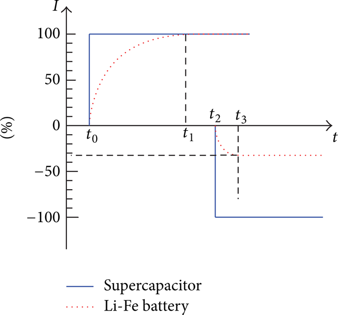
The dynamic features of Li-Fe battery and supercapacitor.
As illustrated in Figure 2, the Li-Fe battery is operated as the lower dynamic power source to provide steady operation energy demand while supercapacitor is operated as the higher dynamic power source to provide the fast dynamic power supply. In this work, it can be constrained by the following:
Based on the objective function, if an optimal solution can be obtained, a hybrid power system can provide the best performance with better sources usage and much lower installed capacities.
3.2. Energy Management Strategy
In this section, we propose an energy management strategy to dynamically assign current parameters of Li-Fe batteries and supercapacitors in a hybrid power system according to the load current I L and the SoCs so as to minimize the gap between the power demand and power supply provided by the hybrid power system and keep the SoCs of Li-Fe batteries and supercapacitors at an optimal or near-optimal level. There are two fundamental problems that need to be solved. Firstly, at the high level management strategy, rules of current flow should be provided for the correct operation range of Li-Fe battery and supercapacitor. Secondly, at the low level management strategy, current parameters need to be given.
3.2.1. Rules of Current Flow
The high level management strategy for current flow is defined based on a set of rules, determined by the working process of the hybrid power system and expert knowledge. The working process of the hybrid power system is briefly described as follows.
A robot will work at the preliminary charging mode, when the system is in the standing mode. As depicted in Figure 3(a), the current flow direction is dependent on the SoCs’ level of batteries and supercapacitors.

The power flow for a typical robot working mode. ((a) I L = 0: Case I and Case II: standing. (b) I L > 0: Case III: starting, high acceleration or heavy load. (c) I L > 0: Case IV and Case V: steady operation or light loading. (d) I L < 0: Case VI and Case VII: deceleration or braking).
Figure 3(b) gives the other important working mode. When a robot starts, accelerates or overloads, instantaneous high power supply is demanded. Then the robot will be driven by both batteries and supercapacitors. Because a supercapacitor has the short-term high discharge current capacity, most current will be provided by the supercapacitor.
When a robot works at the steady operation mode or light loading mode, the battery can provide enough power to meet system requirements. So, batteries are the only power source supply energy. This mode is indicated in Figure 3(c). At this time, when the SoC of supercapacitors is less then SoCscbest, supercapacitors are charged from batteries in advance. Then supercapacitors have enough energy to cope with the instantaneous large current output in the near future.
As described in Figure 3(d), the part of the robot kinetic energy will transform into electricity during the robot deceleration or braking. Most of the energy will be stored in supercapacitors and some of them will be stored in batteries when the SoC of supercapacitors is more than SoCscbest. This can improve the utilization rate of limited electricity.
There are 7 cases for the current flow which are dependent on the different working modes described above. The details of the high level energy management strategy are presented in Algorithm 1.
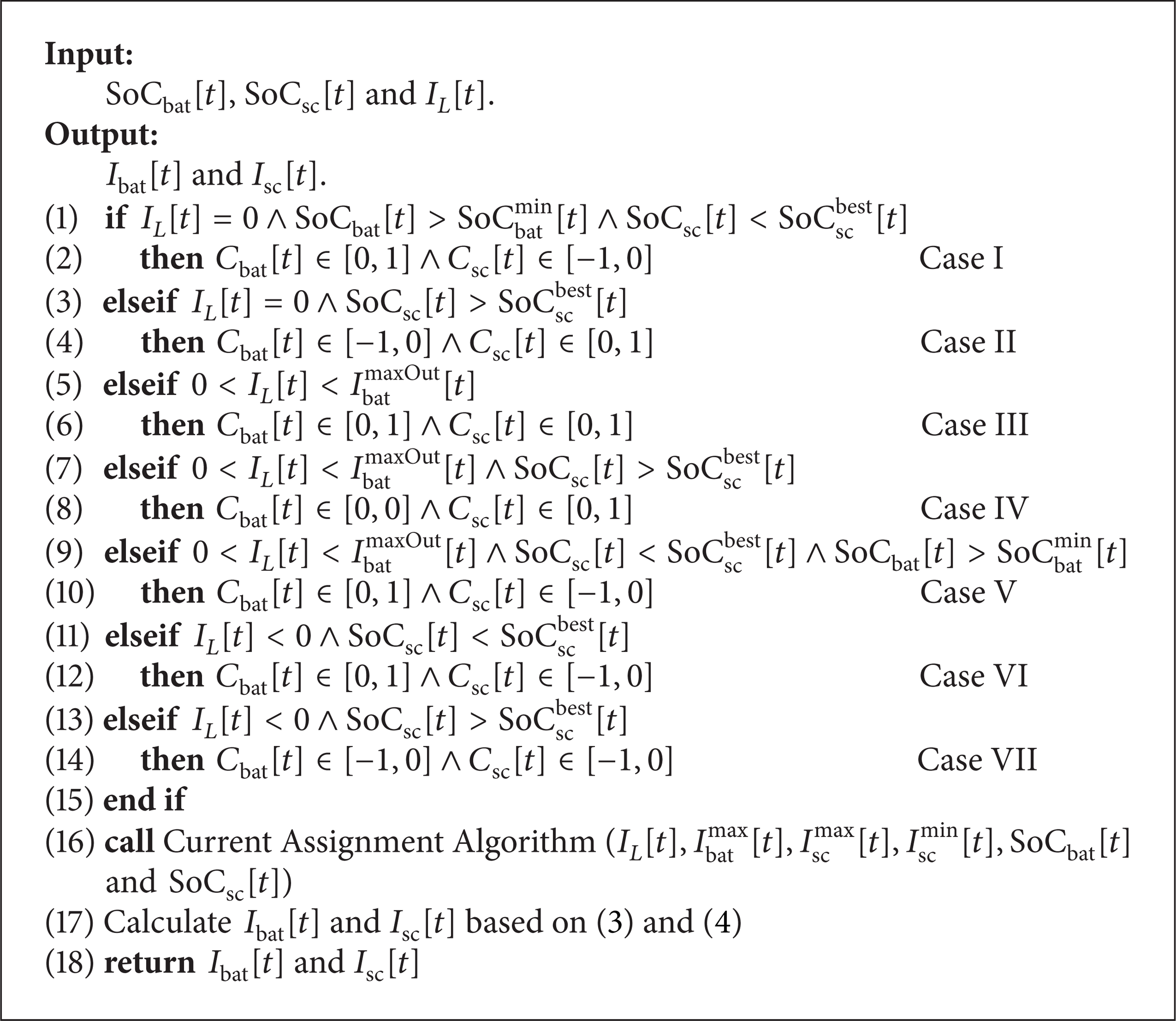
Rules of current flow.
In Algorithm 1, Cases I and II are for the preliminary charging mode. This mode means that there is no power requested. On the other hand, there is no current flow to load. One case is that battery charges for the supercapacitor, when SoCbat[t] is larger than SoCbatmin[t] and SoCsc[t] is less than SoCscbest[t]. The other case is that current flows from supercapacitor to battery, when SoCsc[t] is more than SoCscbest[t]. Case III indicates the three kinds of working status of the robot, including starting, accelerating and overloading. This case demands much more energy. Both battery and supercapacitor provide energy to robot. Steady operation or light loading working mode has two cases, namely, Cases IV and V. Case IV shows battery as the only power source supply energy to the system. When SoCsc[t] is less than SoCscbest[t] and SoCbat[t] is more than SoCbatmin[t], Case V is triggered. Cases VI and VII are for the last working mode: deceleration or braking. In this mode, both battery and supercapacitor have the ability to recycle energy. The current flow direction is mainly decided by the SoC level of supercapacitor.
3.2.2. Current Assignment Algorithm
This level management strategy has been implemented using an improved genetic algorithm to obtain an optimized online current sharing between power sources. The algorithm computes current assignment factors Cbat[t] and Csc[t] in real-time. The current from each source is used to meet the system demand. The supercapacitor is used to provide the high peak power so as to avoid overloading in the charge and discharge process and fluctuating in battery power.
The low level management strategy which is based on the current assignment algorithm can give current distribution specifically. The current assignment algorithm is an adaptive genetic algorithm based on distance measurement [17] which is presented in Algorithm 2. The algorithm defines the distance intensity D i . The distance intensity reflects the distribution of other individuals around an individual. The smaller distance intensity indicates that the distribution of individuals is concentrated. For intensive individuals, there should be a greater probability of crossover and mutation to produce more new individuals to increase the diversity of population. N is the number of individuals in the group and M is the number of genes in each individual. The initial solution considered in our experiments had Cbat[t] = 0 and Csc[t] = 0. After iteration times are defined, the search space can be reduced depending on the SoC level of each source and I L . The algorithm is with high convergence probability, rapid evolving speed, and good stability.

Current Assignment Algorithm.
4. Performance Evaluation
To evaluate the performance of our energy management strategy, a series of experiments have been conducted. We have conducted experiments with instantaneous large charging and discharging. We also simulated a representative load current curve which contains four working modes. The major performance metric to be evaluated is the current flow assignment and the SoC levels for batteries and supercapacitors. In this section, we first introduce the experimental environment. Then, we present and analyze the results.
4.1. Experimental Setup
In the experiment, we developed a simulator which simulates a hybrid power system with Li-Fe batteries and supercapacitors. The hybrid power system architecture is depicted at Figure 1. Three parameters, Iload, SoCsc, and SoCbat, are monitored and given as the feedback. With our energy management strategy, the hybrid power system gets the current distribution information.
The simulation is conducted on a PC with Intel Core i5-3337U and 4 GB memory running Windows OS. The Li-Fe battery is set at 1.5 Ah and the supercapacitor is set 5 F. The characteristics of power sources are presented in Table 1. The Li-Fe battery can provide a maximum continuous current of 4.5 A with 5.6 kg, and its specific energy is about 51.4 Wh/kg. The electric quantity of the supercapacitor with same weight only has 72 C and its specific energy is about 1/75 of the Li-Fe battery. But the supercapacitor has a maximum current of 500 A. To increase the specific power of the supply system, the supercapacitor offers a large specific power; so it is a good complement to the Li-Fe battery. The supercapacitor current can either be positive or negative, which allows the energy to be transferred on both directions.
Power sources characteristics.

The simulation tests are based on the current flow of mobile robot demands. We simulate two kinds of load current: constant charge or discharge current and typical current which contains starting, high acceleration, steady operation, braking, and other working modes with in 60 s as shown in Figure 4.

Current demands for the mobile robot.
4.2. Results and Discussion
Figure 5 presents the results for four different constant currents of load. They are Iload = 4 A, Iload = − 4 A, Iload = 8 A, and Iload = − 8 A. All results are under SoCbatinitial = 100% and SoCscinitial = SoCscbest = 80%. In Figures 5(a) and 5(b), the mobile robot works at the starting mode, high acceleration mode, or overloading mode. It can be observed that the supercapacitor current synchronously changes when load current suddenly changes. The battery current increases slowly based on the dynamic features to the maximum discharge current. However, as shown in Figure 5(b), supercapacitor discharges all of its energy after 15.3 s. Then the current of the supercapacitor decreases to 0 when the current of the battery has reached maximum discharge current. Region A in Figure 5(b) reflects a 3.5 A gap between the supply and demand.

The performance of the hybrid power system for the constant current of load ((a) Iload = 4 A. (b) Iload = − 4 A. (c) Iload = 8 A. (d) Iload = − 8 A).
In Figures 5(c) and 5(d), the mobile robot works at the high deceleration mode or braking mode. Most of the regenerative energy at the deceleration or braking mode is stored in supercapacitors, and some energy is also transferred to Li-Fe battery. Region B in Figure 5(d) means that the SoC level of the supercapacitor has reached 100% after 9.3 s. Because the regenerative current is larger than the maximum charge current of the Li-Fe battery, not all the energy can be recycled. The performance of the model on these constant charges or discharge currents indicates that our energy management strategy can perform well under different conditions.
Figures 6 and 7 report overall performance on the test set which is a typical current containing all working modes given in Figure 4. Two curves in each graph show the current supplies from Li-Fe batteries and supercapacitors, respectively. Figure 6 describes the performance of the hybrid power system for the typical current of load with the changes of SoCscbest from 70%, 80% to 90% and with the same SoCbatinitial = 80% and SoCscinitial = 80%. Figure 7 presents the performance of the hybrid power system with the changes of SoCscinitial from 60%, 80% to 100%. All the situations shown in Figure 7 use the same parameters SoCscbest = 80% and SoCbatinitial = 100%.
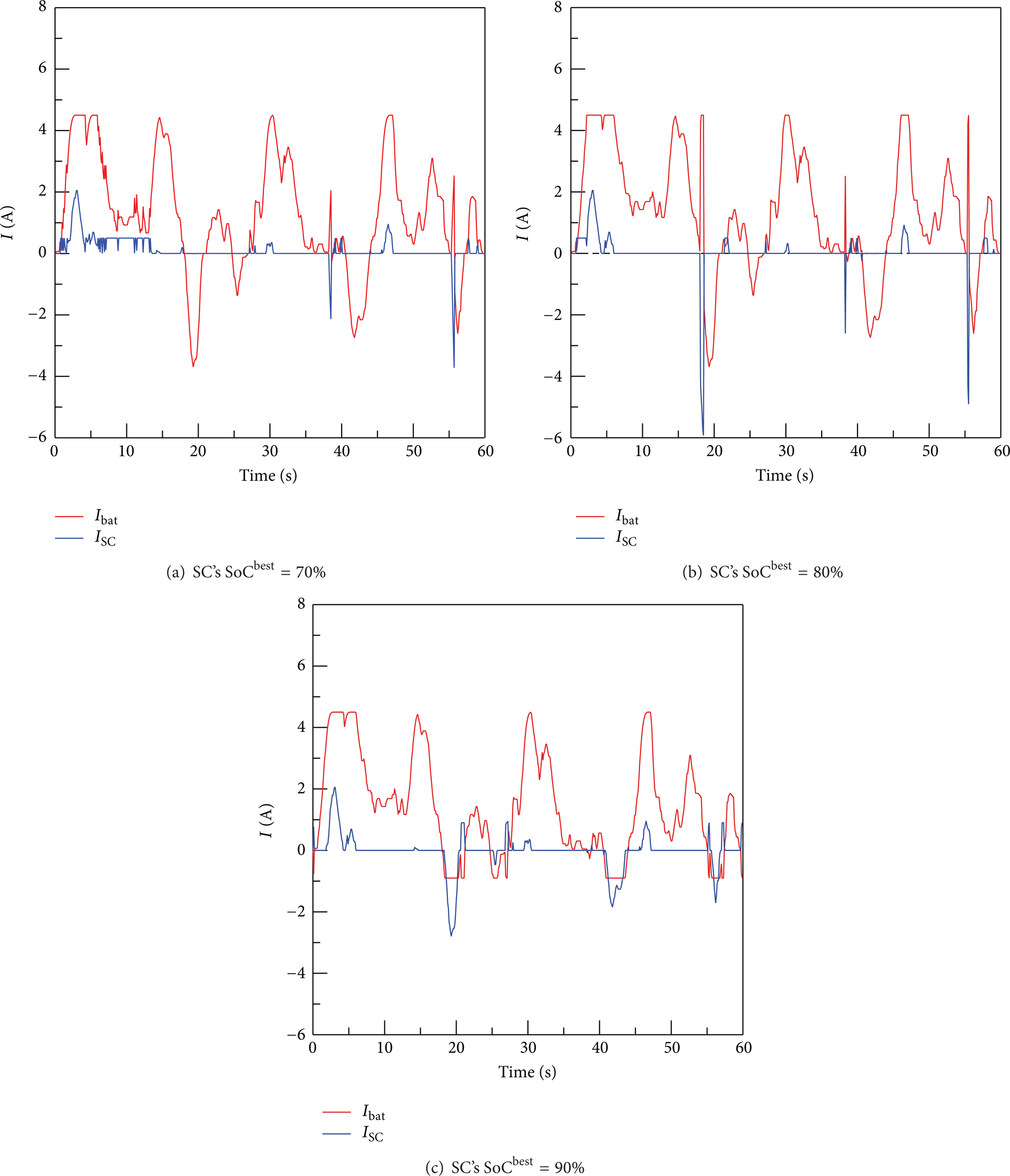
The performance of the hybrid power system for the typical current of load with different SoCscbest value (SoCbatinitial = 80%∧SoCscinitial = 80%).

The performance of the hybrid power system for the typical current of load with different SoCscinitial value (SoCbatinitial = 100%∧SoCscbest = 80%).
Figure 6 presents the solutions obtained by our energy management strategy. Different initial parameter SoCscbest of the hybrid power system have different performance. In Figure 6(a), SoCscinitial is larger than SoCscbest (SoCscinitial = 80% and SoCscbest = 70%). The supercapacitor not only provides high-frequency current but also recycles small part energy when the current is much larger when SoCscinitial is equal to SoCscbest (SoCscinitial = 80% = SoCscbest = 80%). Recycling energy capacity of the supercapacitor is the same as shown in Figure 6(b). However, in order to keep the SoC level of the supercapacitor at the best level, the supercapacitor only provides instantaneous large current but does not discharge high-frequency current. Figure 6(c) means SoCscinitial is less than SoCscbest (SoCscinitial = 80% and SoCscbest = 90%). It is shown that the supercapacitor provides instantaneous large current and stores larger part of regenerate energy during braking or deceleration.
According to Figure 7, the system has distinct performance with different initial parameter SoCscinitial. As depicted in Figure 7(a), SoCscinitial is 20% less than SoCscbest. So, the supercapacitor can store most of the regenerate energy. But it does not discharge high-frequency current, when SoCscinitial is equal to or larger than SoCscbest as described in Figures 7(b) and 7(c). The supercapacitor provides instantaneous large current and high-frequency current. It also recycles small part of energy to keep an optimal SoC level. The experimental results show that our strategy can improve the dynamic performance of mobile robots and extend the battery life.
5. Conclusions and Future Work
In this paper, we proposed an energy management strategy of a Li-Fe battery and supercapacitor hybrid power system to provide both high power density and energy density for mobile robots with fluctuating workloads. A two-phase power-optimization approach has been proposed to exploit the high power density of supercapacitors and the high energy density of Li-Fe batteries. The experimental results show that our strategy can effectively improve the performance of mobile robots and extend the lifetime of batteries.
There are several directions for future research. First, it is an interesting problem for how to utilize our energy management strategy for path planning and navigation in mobile robots. Second, various energy optimization techniques have been proposed to optimize real-time task scheduling [18–21]. We will study how to combine our strategy with these task-level energy optimization techniques.
Footnotes
Notations
Conflict of Interests
The authors declare that there is no conflict of interests regarding the publication of this paper.
Acknowledgments
This work received financial support from the National Natural Science Foundation of China (no. 61070049 and no. 61202027), the National Key Technology R&D Project (no. 2012DFA11340), the Beijing Natural Science Foundation of China (no. 4122015), and the Beijing City Board of Education Science and Technology Development Project (no. KM201210028001).