
Abstract
Radio Frequency IDentification (RFID) has been increasingly used to identify and track objects automatically. RFID has also been used to localize tagged objects. Several RFID localization schemes have been proposed in the literature; some of these schemes estimate the distance between the tag and the reader using the Received Signal Strength Index (RSSI). From a theoretical point of view, RSSI is an excellent approach to estimate the distance between a sender and a receiver. However, our experiments show that there are many factors that influence the RSSI value substantially and that, in turn, has a negative effect on the accuracy of the estimated distance. Another approach that has been recently proposed is utilizing transmission power control from the reader side. Our experiments show that power control results are more stable and accurate than RSSI results. In this paper, we present a test-bed comparison between the power control and the RSSI distance estimation approaches for active RFID tags. We also present the Angle of arrival Cluster Forming (ACF) localization scheme that uses both the angle of arrival of the tag's signal and the reader's transmission power control to localize active tags. Our experiments show that ACF is very accurate in estimating the location of active RFID tags.
1. Introduction
Radio Frequency IDentification (RFID) is a wireless technology that has enabled a wide range of identification, monitoring, and tracking applications. This includes using RFID for supply chain management, access control, identification and tracking of patients and children, and smart environments.
An RFID system is composed of tags (or transponders), readers, and a software application. A tag is usually attached to an item for the purpose of identifying and/or tracking it automatically. RFID tags store some identification data and transmit this data to the RFID reader via Radio Frequency (RF) signals. The RFID reader broadcasts a query to all tags within its reading (interrogation) range. Tags that receive the broadcasted query respond by sending their data back to the reader [1, 2].
RFID tags are composed of three main components: an Integrated Circuit (IC), an antenna, and substrate. Based on the power source, tags can be classified into three types: passive tags, semipassive tags, and active tags. Passive tags do not have a power source; they rather get powered by the electromagnetic waves that are emitted from the reader to broadcast the query [1–3]. Semipassive tags have an onboard battery that is used only to power their circuits for processing. However, the battery is not used for communication. As is the case with passive tags, semipassive tags rely on the reader to get the power they need for communication. An active tag has a battery that is used for both powering up the circuit and communicating with the reader. An active tag can handle a two-way communication with the reader independently [4].
RFID has the potential to enable many interesting applications and to play a crucial role in the envisioned Internet of Things (IoT). However, achieving that requires solving some technical problems. One of these problems is estimating the location of a tag precisely, which is the focus of this paper. Accurate localization of an RFID tag is the key to many tracking and monitoring applications. An example of such applications is an alarm system that predicts dangerous situations (e.g., a child walking toward an oven).
Several RFID localization schemes have been proposed in the literature. Most of these schemes find the location of a tag based on an estimate to the distance between the tag and multiple readers. The accuracy of the estimated location depends primarily on the estimated distances to multiple readers. Estimating the distance between a reader and a tag can be made either by using the Received Signal Strength Index (RSSI) or by controlling the transmission power of the reader.
In this paper, we look into the problem of localizing an active RFID tag precisely. We have conducted a test-bed experiment to evaluate and compare RSSI-based and power control-based schemes. We also propose the Angle of arrival Cluster Forming (ACF) scheme which uses a combination of the Angle of Arrival (AoA) and the reader's transmission power control. Our experiments have shown that ACF is very accurate in estimating the location of active RFID tags.
The rest of the paper is organized as follows. Section 2 surveys related work. Section 3 presents our test-bed experiments for RSSI-based and power-control-based distance estimation approaches. Section 4 presents our ACF scheme for active RFID localization. Section 5 concludes the paper with a brief summary and some future research directions.
2. Related Work
Many localization schemes have been proposed in the literature. The SpotON system, which was proposed in [8], is a general wireless localization scheme that uses RSSI measurements and the triangulation method. The scheme is based on using multiple base stations (readers) that provide RSSI measurements for the target object (tag) to be used to estimate its location. However, this system has a low accuracy in RFID because of the unpredictable behavior of the RF signals especially with passive tags.
A famous RFID localization scheme is the LocAtioN iDentification based on dynaMic Active Rfid Calibration (LANDMARC) which was proposed to localize active tags in indoor environments [9]. LANDMARC uses reference tags to serve as reference points in known locations. LANDMARC estimates the location of a target tag whose location is unknown by comparing its RSSI with those of reference tags. LANDMARC is considered to be a cost-effective localization scheme as it uses more reference tags instead of using more readers. The authors in [10] proposed the VIrtual Reference Elimination (VIRE) scheme which extends the LANDMARC scheme by using virtual reference tags in addition to the actual reference tags. RSSIs of virtual reference tags are calculated and used to enhance the accuracy of the localization process. Another enhancement to the LANDMARC scheme was presented in [11]. This scheme divides the area into a number of subareas and finds two estimates for the location. The first estimate is calculated using the LANDMARC scheme and the second estimate is calculated using a new estimation algorithm. The estimation algorithm starts by creating a vector of average Euclidean distances between each area and the target object. The area with the lowest average Euclidean distance is chosen to be the second location estimate for the target object.
In [12], a scheme for localizing active and passive mobile tags is proposed. It uses RSSI and reference tags placed on the floor and the ceiling of the environment. In [13], the authors proposed an approach that utilizes connectivity information of readers and virtual reference tags only to locate a target tag. Experiments have shown a fine-grained accuracy for 2D localization as well as an acceptable accuracy for 3D localization. The authors in [14] presented an RFID smart shelf using passive UHF RFID tags to localize tags by detecting interference with reference tags.
Another approach that can be used is utilizing power control from the reader side which was proposed initially as an anticollision protocol [15–17]. The main idea is to adjust the reader's transmission power level (i.e., its interrogation range) in order to estimate the distance between the reader and the tag. The distance is associated with the lowest power level at which the tag is detected. In other words, the power level is mapped to a distance [18].
In the literature, several AoA-based schemes are proposed for localizing UHF RFID tags. In [6, 7], three uniform linear antenna arrays with three patch elements are used to localize active tags using the AoA. The AoA of the received tag signal is measured at each of the three antenna array positions. However, previous work did not pay attention to errors in AoA measurements and their effect on the localization process. The work in [19–21], for example, assumes that AoA measurement error is uniform over all angle readings.
More details about existing localization schemes can be found in some survey papers about this topic (see [22, 23]).
In this paper, we examine the sole use of RSSI or power control approaches as an initial, yet coarse, step to localize active RFID tags. Even though AoA is an attractive localization method, we show that existing AoA estimation methods comprise high error rates due to the phase measurement correlation. Therefore, we propose a localization method that augments the power control approach with a new AoA method that minimizes the phase measurement correlation and, hence, provides higher accuracy.
3. Test-Bed Evaluation of RSSI and Power Control Distance Estimation
Since most existing distance estimation schemes are based on either tags RSSI or readers power control, we present a test-bed evaluation for both approaches. We use the following devices in our test-bed. We use GAO RFID 217001B active reader and GAO 127002 active tags [24]. The interrogation range of the reader can be adjusted from 5 m to 100 m, and it can read up to 100 tags/second. Its operating frequency ranges from 2.4 GHz to 2.5 GHz. This reader comes with an Application Programming Interface (API) library that makes an interface for the reader to control its operation by external software. It has a dynamic transmission power that is configurable by an API function.
3.1. RSSI Distance Estimation
We evaluated the approach of using RSSI (only) for estimating the distance between readers and tags. The distance is estimated based on mapping the RSSI readings of the tag's response to a distance based on a reference curve (i.e., a mapping table) associating RSSI readings to distances. We placed tags at distances that range from 1.5 m to 15 m with intervals of 1.5 m (i.e., 10 locations) with 10 dBm transmission power from the reader. We had the following observations.
The same tag at the same location gives different RSSI readings. A tag may give an RSSI reading that is larger than that of another tag that is closer to the reader.
The reason behind these two observations is the fact that RSSI in general is unstable and very sensitive to tags orientation and different environment effects. We also took the average RSSI reading out of multiple readings with different orientations. The result is illustrated in Figure 1 which shows the average RSSI reading and the variance for each distance. The obtained results are unstable and inaccurate. For instance, at short distances, the readings of a tag placed at 4.5 m from the reader overlap with the readings of a tag placed in the range from 4.5 m to 9 m, which produces an error margin of 4.5 m (i.e., 100% of the actual distance). At longer distances, the readings of a tag placed at 10.5 m overlap with the readings of a tag placed in the range from 10.5 m to more than 15 m. This makes RSSI-based localization unsuitable for both indoor and outdoor applications.

RSSI values of active tags from an active reader with 10 dBm transmission power.
RSSI fluctuations are worse with passive tags because of the use of backscatter modulation [4] to reflect the reader's low-power signal. In [5], an evaluation of RSSI efficiency for distance estimation is conducted and the results are shown in Figure 2. Figure 2 shows the distribution of the measured RSSI and the mean of these values under the following conditions: 30 dBm transmission power, 1 m height for antennas and tags, and 6 dBi reader's antenna gain. The reported results exhibit a similar error trend as that of the active tags in Figure 1.
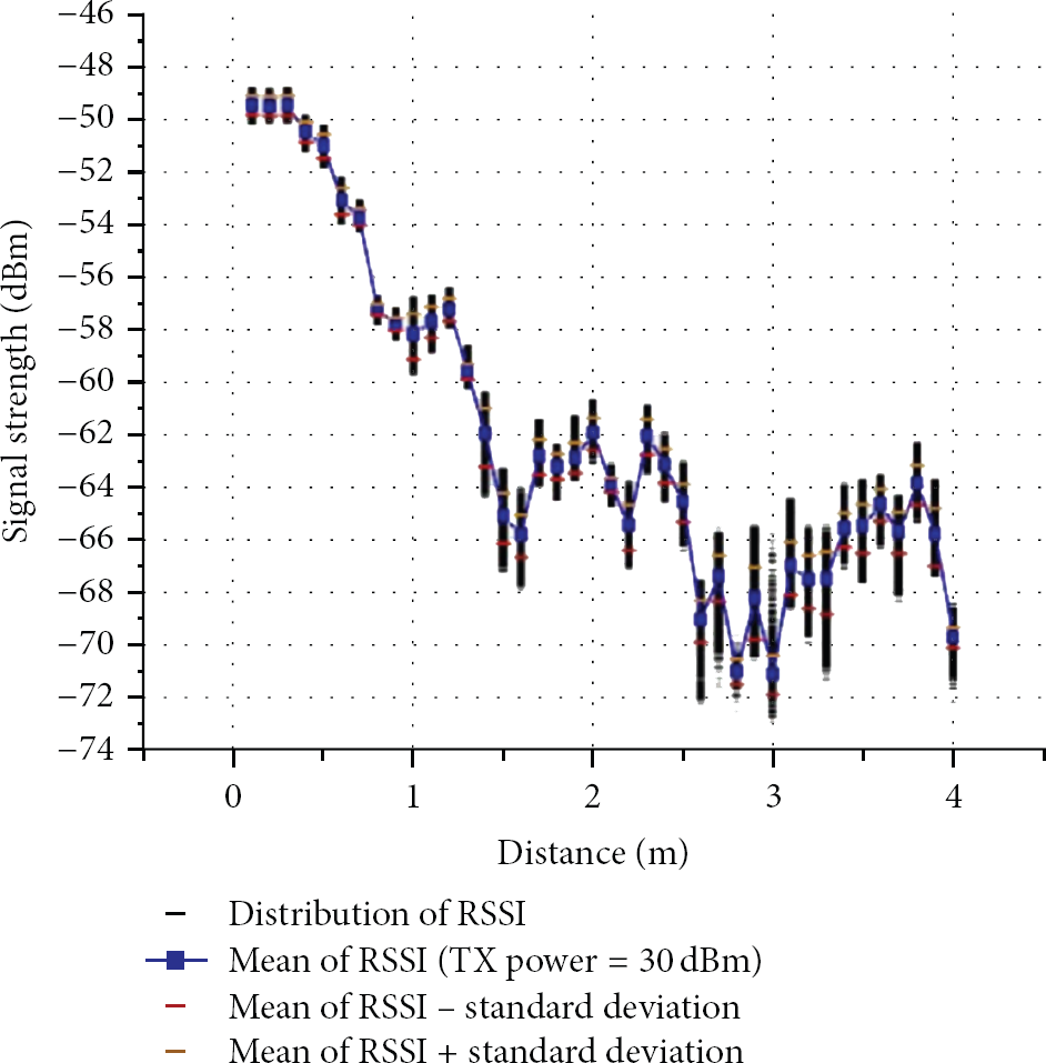
Relationship between RSSI values and distance for passive tags [5].
The main conclusion we have out of this experiment is that RSSI cannot be used to accurately measure the distance between a tag and a reader. In fact, even reference tags do not help here as it is common to have very different RSSI readings from the same tag in the same location and at almost the same time.
3.2. Power Control Distance Estimation
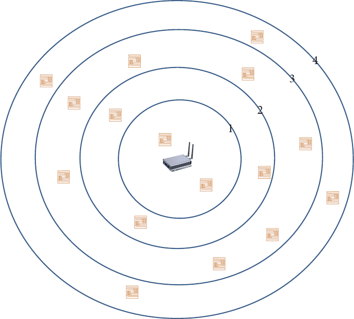
Another method to estimate the distance between a tag and a reader is to adjust the transmission power and, hence, the transmission range of the reader. This way the distance is associated with the minimum transmission range at which the tag is identified as shown in Figure 3. We conducted a comprehensive experiment to evaluate the stability and accuracy of this method. We placed tags at distances that range from 1 m to 19 m with intervals of 2 m (i.e., 10 locations). The RFID reader has 31 transmission levels. In our experiment, the reader interrogates tags 100 times at each transmission level. For each combination of a distance and a transmission level, we find the percentage of times the tag is identified by the reader. The results of this experiment are shown in Table 1. The results are much more stable than the RSSI results. We observed that tags located in the same location give very consistent results.
Relationship between distance and transmission power.

Estimating the distance using power control.
4. Angle of Arrival Cluster Forming (ACF)
In the previous section, we have seen that power control can give good estimates for the distance between a reader and a tag. This divides the area surrounding the readers into discrete regions in which tags are expected to reside. In this section, we propose a scheme that augments the highly precise AoA localization method with the power control distance estimation method. We implement a method for estimating the AoA using the phase difference in the 2.45 GHz range. Experimental results are presented to assess the performance of the proposed scheme.
4.1. Overview
Finding the AoA of the tag's signal is done by estimating the phase difference of the received tag's signal with respect to known positions of the receiving antenna arrays. And then, the position of the tag is determined to be in the intersection of the two hyperbolas formed by the two antenna arrays.
To estimate the angle of arrival of the tag's signal, we use a phased antenna array composed of two individual antenna elements. The two antenna elements are separated by a distance of

(a) Phase difference calculation. (b) The hyperbolas of antenna 1 and antenna 2.
The two-antenna array provides a solution for the tag's location which is a hyperbola whose focal points are the locations of the two antennas (as shown in Figure 4(b)). If the tag is placed at a point 
This indicates that a single antenna array of two antennas is not enough for a precise localization because any point on the hyperbola is a possible location of the tag. Therefore, deploying more antenna arrays brings overlapping hyperbolas and provides a finer estimate for the tag location.
4.2. Error Modeling
In our design, we utilize the phase difference using the AD8302 chip to estimate the AoA [25]. In order to evaluate the localization accuracy, we conducted an experiment to evaluate the reflected error in the AoA from the error in the measured phase difference. A two-antenna array (with
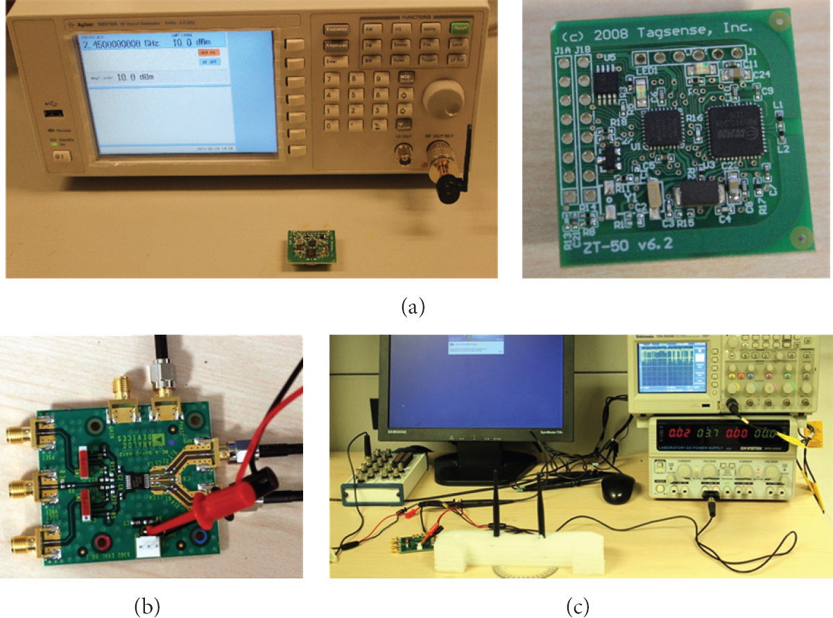
(a) RF signal generator and an active tag. (b) AD8302 phase shift detector board. (c) The two-antenna array is connected to the phase difference module and the output is connected to the oscilloscope and data acquisition board.

The output voltage from the phase difference module when shifting the antenna array from 0 to 90 degrees (causing a phase difference from 0 to 180 degrees).

The error (in degrees) between the actual and the measured phase shifts.
4.3. Deployment of Phase Detectors
When the two detectors are placed beside each other as in [6, 7, 21], the phase estimation error has a significant impact on the location estimation. As shown in Figure 8(a), for each phase detector n there is a phase error margin that results in upper and lower limits to the expected phase,

To provide a fine estimate for the tag's location, we place two phase detectors at a distance that is much larger than the wavelength λ. The phase reading from each detector makes a hyperbola and the tag's location is estimated to be along the edge of that hyperbola. As the phase reading has a variable margin of error [25], we consider the upper and lower limits of the phase difference in estimating the location. When the phase detectors are separated as shown in Figure 8(b), the same phase error results in a much smaller error area than that in Figure 8(a). The deployment in Figure 8(b) results in two clusters of points which are close to each other.
4.4. Combined Power Control and ACF
The power control scheme provides a good estimate for the distance between the tag and the reader. Thereby, the ACF can utilize the power control distance estimation to consider only one of the location clusters (as in Figure 8(b)). In our evaluation, two phase detectors and one active tag reader are placed as shown in Figure 9(a) with a separation of 4 m (with an operating frequency of 2.4 GHz). An active tag is placed at the grid nodes in Figure 9(a) that covers an area of 3 × 4 m2. The experiment area is then mapped to the Cartesian plane with the lower corners at (−2, 0.5) and (2, 0.5) and the upper corners at (−2, 3.5) and (2, 3.5) with one phase detector at the origin and another at (0, 4). The localization error is calculated based on the Euclidian distance between the estimated location and the actual location. The error at each node is plotted in Figure 9(b). Note that most of the nodes have an error of less than 0.1 m indicating a robust localization performance of our scheme. When the tag is at the middle nodes, the phase difference becomes close to zero and the error rises dramatically as depicted in Figures 7 and 9(b). The error rises also when the tag is at the corner of the grid where the phase difference is close to 180 degrees. The average error of the 169 locations is 0.135 m.

(a) The grid in our experiment. (b) Estimated error for each point in the grid in (a).
5. Conclusion
In this paper, we present a test-bed study and comparison between the RSSI and the power control distance estimation approaches for active RFID tags. We found that the power control approach is much more stable and accurate than the RSSI approach. We also present a novel scheme for localizing active tags, which is the ACF deployment, that takes advantage of the robustness of the AoA of the tag's signal and the accurate estimated distance from the power control approach to localize active tags accurately. Our experiments have shown that a combination of the ACF and power control is able to locate active tags with a high accuracy (an average of 13.5 cm error) using a single RFID reader (with adaptive gain) and two phase detectors.
Our future work includes combining the ACF and power control with the use of reference tags to improve the accuracy in some particular spots in which the AoA module is expected to suffer low accuracy (e.g., middle nodes and corners of the grid).
Footnotes
Conflict of Interests
The authors declare that there is no conflict of interests regarding the publication of this paper.
Acknowledgment
This research is supported by the National Plan for Science and Technology Program at King Saud University, Project no. 11-INF1500-02.