
Abstract
This paper presents a nonlinear vibration model of rolling element bearings with 5 degrees of freedom based on Hertz contact theory and relevant bearing knowledge of kinematics and dynamics. The slipping of ball, oil film stiffness, and the nonlinear time-varying stiffness of the bearing are taken into consideration in the model proposed here. The single-point local fault model of rolling element bearing is introduced into the nonlinear model with 5 degrees of freedom according to the loss of the contact deformation of ball when it rolls into and out of the local fault location. The functions of spall depth corresponding to defects of different shapes are discussed separately in this paper. Then the ode solver in Matlab is adopted to perform a numerical solution on the nonlinear vibration model to simulate the vibration response of the rolling elements bearings with local fault. The simulation signals analysis results show a similar behavior and pattern to that observed in the processed experimental signals of rolling element bearings in both time domain and frequency domain which validated the nonlinear vibration model proposed here to generate typical rolling element bearings local fault signals for possible and effective fault diagnostic algorithms research.
1. Introduction
Rolling element bearings are very important components in rotary machines whose dynamic behavior has a great effect on transmission systems of industry production lines. The local fault of the rolling element bearings would induce the severe mechanical defects and economic losses. Hence, it is very important to do some research on the fault diagnosis and fault prediction to prevent serious accidents and reduce the production costs. The basis and key of bearing fault diagnosis is to obtain the vibration response signals of the bearings. Traditional method is to obtain the vibration signal by setting faults artificially in experiments or waiting for the natural occurrence of defects in production, which needs long period and great cost. From the point of dynamics, the generation mechanism of rolling element bearings defect is thoroughly researched in this study. Besides, efficient nonlinear vibration model of faulty rolling element bearings is established and local fault signals of the bearings are simulated which can be used to get typical rolling element bearings local fault signals for possible and effective fault diagnostic algorithms research.
Domestic and foreign researchers have carried out intensive studies on the rolling element bearings dynamics and defect mechanism. Fukata et al. proposed a dynamic model with 2-DOF (degree of freedom) based on Hertz contact theory [1]. The nonlinearity of the rolling element bearing and time-variant characteristics were taken into account. Wijnant et al. summarized the researches about the impact that elastohydrodynamic lubrication brings to rolling element bearing dynamics. Elastohydrodynamic lubrication theory was introduced into the rolling element bearing model, and a computation model for the problem of elastohydrodynamic lubrication and structural dynamics was built [2]. Tiwari et al. studied the influence of bearing windage on the vibration response of rigid rotor system. They came to the conclusion that, with the increase of bearing clearance, the nonlinearity of the rotor system increased [3, 4]. Feng et al. researched further on the model with 2-DOF, considering the impact of bearing cage and ball slide. Also, the influence of vibration response for the defect in inner and outer race was studied [5]. Sopanen and Mikkola proposed a more comprehensive bearing dynamics model, including the influence of different geometric defects (surface roughness, surface waviness, and partial and distributed defect) on the bearing model [6, 7]. Cong et al. proposed a rolling element bearing fault model based on the dynamic load analysis of a rotor-bearing system to make a simulation considering several parameters such as the imbalance of the rotor and the location of the defect on the surface [8]. Up to now, the researches on the rolling element bearing dynamics mainly focus on the dynamic behavior of the normal bearing or the whole rotor system supported by the bearing. Although some other researchers did some research about the dynamics of the fault bearings but the study of the dynamic behavior of defect bearings is relatively rare [9–11]. At the same time, high resonant frequency of the system caused by local fault of the rolling element bearing generally exceeds 1–5 kHz, but the majority of resonant frequencies caused by bearing defect model built based on rotor dynamics do not reach such a high level. Moreover, most of the existing researches on defect bearing dynamics show that when the rolling element moves over the defect, the released deformation is the depth of defect. Nevertheless, the actual deformation released would be different according to the damage degree of the bearing. Based on the previous studies [12], unit resonator was introduced. For the defect bearing, the high-frequency natural vibration of inner and outer race of bearing, sensor, or other components was simulated by adjusting the rigidity of the unit resonator and damping coefficient. According to the defect size, different functions were used to represent the released deformation. Dynamic models of inner and outer races of rolling element bearing and the defect of the rolling element were set up. By numerical integral method, the fault feature of the rolling element bearing was studied. The research provides the theoretical basis for fault diagnosis of rolling element bearing.
2. Nonlinear Vibration Model of Rolling Element Bearing
Rolling element bearing is made up of outer race, inner race, bearing cage, and rolling elements. Nonlinear vibration model of the bearing with 5-DOF introduced in this paper is shown in Figure 1. The model mainly consists of 4-DOF in the horizontal and vertical direction of inner and outer races and 1-DOF in vertical direction of unit resonator, which are composed of spring-mass systems. High-frequency natural vibration of the inner and outer races of bearing, sensor, or other components under excitation could be imitated by adjusting the stiffness of the unit resonator and damping coefficient when the bearing has defects using the additional unit resonator spring-mass system. The assumptions based on which the model was established are as follows:
lumped mass method is used for each component;
moment of inertia of each component is ignored;
effect of surface waviness of bearing raceway is ignored; it is assumed that there do not exist other geometric errors on the moving contact surface except partial damage;
elastic contact between the rolling element and raceway satisfies the Hertz theory [13];
all dampings are linearly viscous.
Dynamic differential equation of the bearing system is shown as follows:
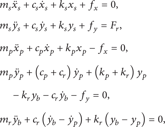
where m s , m p , m r , respectively, represent the mass of inner race, outer race, and unit resonators; k s , k p , k r , respectively, represent the stiffness of inner race, outer race, and unit resonators; c s , c p , c r , respectively, represent the damping of inner race, outer race, and unit resonators; f x , f y , respectively, represent the nonlinear contact force of the bearing in the vertical direction and horizontal direction; x s , x p , y s , y p , y b mean the two inner race DOF, two outer race DOF, and measured vibration response. F r is the vertical force applied to the inner race of the bearing, which is caused by the weight of the shaft and the rotor.

Nonlinear vibration model of rolling element bearing with 5-DOF.
2.1. Nonlinear Contact Force of Rolling Element Bearing
Important parameters of rolling element bearing include the number of balls n b , diameter of ball D b , and pitch diameter of bearing D p . The outer race of rolling element bearing is usually fastened to the bearing pedestal. The inner race rotates together with the rotating shaft. The balls make pure rolling movement on the raceway. Based on the range of radial load during the operation of the rolling element bearing, the raceway is divided into load zone and nonload zone, as shown in Figure 2. The balls that enter the load zone are deformed, producing variation flexibility vibration.

Distribution of radial load.
Total deformation of the jth ball is related to the relative displacement between inner and outer races as well as the angular position of the jth ball and bearing clearance, as expressed by the following equations:
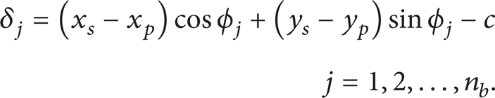
φ j represents the angular position of the jth ball:

where φ0 is the initial angular position of bearing cage, ω c is the angular speed of bearing cage, and ω s is the angular speed of shaft.
From the Hertz contact theory, the contact force between the jth ball and the raceway is given by

According to formula (4), the total nonlinear contact forces of bearing in the x and y direction are shown, respectively, as
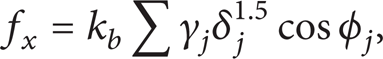
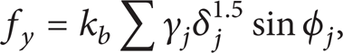
where γ j is a switch function. The ball is deformed only when the ball is located in the load zone, and thus the contact force is produced. Formula of γ j is as follows:

2.2. Effect of Lubrication and Sliding of the Rolling Element
In order to reduce the friction between various components of bearing and to promote the endurance of the bearing, lubricant is usually injected between ball and inner and outer races. An oil film forms between the ball and the surface of raceway, separating the contacting surfaces. Therefore, when the vibration model of the rolling element bearing is established, the influence of oil film should be taken into consideration. Because the oil film occupies part of the bearing clearance and even further leads negative clearance, the bearing stiffness increased. The influence of lubricant film is considered by setting the bearing clearance c in formula (2) as negative.
When the bearing rotates, the rolling element does not make pure rolling movement on raceway. The angular speed of the center of the rolling element is greater than that of the bearing cage in the load zone. The rolling element slides before the bearing cage does. In the nonload zone, the angular speed of the former is smaller than that of the latter. The rolling element slides after the bearing cage does. When considering the sliding, the angular position of the jth ball is expressed as


where ξ j is +1 when the rolling element is located in the load zone, while in the nonload zone, ξ j is −1. Δf/f m × 100% shows the mutation percentage of average contact frequency, with the value ranging between 1% and 2%. Hence the corresponding value of φslip is (0.01 rad∼0.02 rad) [14].
3. Model of Rolling Element Bearing Fault
When local fault happens to the inner and outer races of rolling element bearing or the rolling element, the ball moving over the site of local fault of the ball would release some deformation. The deformation of the jth rolling element entering the spall is expressed as

Deformation formulae (10) and (8) of the rolling element with defect are substituted into formulae (5) and (6). The nonlinear contact force is calculated and substituted into dynamic equation (1) of bearing vibration model. The solution of the differential equation is the vibration response of the rolling element bearing with defect.
3.1. Local Fault Model of Inner and Outer Races of Rolling Element Bearing
When the local fault occurs to the inner and outer races, the depth of the local fault is defined as c d , angle spanned by the defect Δφ d , and angular position of the defect φ d . Figure 3 shows the diagram of model of outer race defect and some geometric relations. Switch value β j in formula (10) is defined as follows:


Schematic diagram of outer race defect model.
The defect on the outer race of the bearing in the load zone has a fixed position and φ d is a constant value. The defect on the inner race of bearing changes with the rotating inner race. The φ d is a variable value, φ d = ω s t + φd0; φd0 is the initial angular position of the defect.
3.2. Model of Bearing with Fault on Ball
When the rolling element has a local fault, it will get into contact with inner and outer races for one time, respectively, during each revolution of that of rolling element. Since the raceway curvature radiuses of inner and outer races are different, the angle spanned by the spall Δφ d differs. When the ball is in contact with the inner and outer races, the maximum spall depths are different as well. Hence when the spall happens to the rolling element, the definition of β j is adjusted:

where x means half of the spall width.
3.3. Improvement of Fault Model [15]
When the rolling element bearing has a local fault, the ball rolling over the site of local fault would release some deformation. In the existing researches on the dynamics of the partial bearing with defects, the released deformation is simply treated as constant value of the defect depth. However, the practical deformation released differs with defect shape as well as the ratio of the defect size and that of the ball.
The size ratio of ball to defect is defined as

Ratio of length to width of defect is defined as

where L and B represent the length and width of the defect, respectively.
According to the size ratio of the defect and the ball and the ratio of length to width, there are five situations of defect as shown in Figure 4. (1) When the defect is only a crack, that is, the ball size is far greater than the defect size, there is η bd ≫ 1, as shown in Figure 4(a). (2) When the ball size is similar to the defect size, and the defect width is greater than the length, η bd > 1 and η d < 1, as shown in Figure 4(b). (3) When the ball size is similar to the defect size, and the defect width equals to length, η bd > 1 and η d = 1, as shown in Figure 4(c). (4) When the ball size is similar to the defect size, and the defect width is equal to the length, η bd > 1 and η d > 1, as shown in Figure 4(d). (5) When ball size is far smaller than the defect size, η bd ≤ 1, as shown in Figure 4(e).

Defects of different sizes (a) η bd ≤ 1, (b) η bd > 1 and η d < 1, (c) η bd > 1 and η d = 1, (d) η bd > 1 and η d > 1, and (e) η bd ≤ 1.
According to the five types of the defect in Figure 4, the defect depth reached by the ball could be divided into three cases. (1) When the defect belongs to the first type, the lateral surface diagram of the ball moving over the defect is shown as Figure 5(a). The ball leaves the defect as soon as it gets in contact with the defect. Now the defect depth can be expressed by a rectangular function in Figure 5(b); that is, defect depth is always a constant value. (2) When the defect belongs to the second and third type, the lateral surface diagram is shown as Figure 5(c). When the ball is moving over the defect, defect depth reached by the ball gradually increases with the rotating ball. After the defect depth reaches the maximum, it gradually decreases. It could be expressed by half sine function shown in Figure 5(d). (3) When defect belongs to fourth and fifth type, the diagram of ball moving over the defect is shown as Figure 5(e). With the rotation, the defect depth that could be reached gradually increases. It remains unchanged for some time after reaching the maximum and then decreases again. This can be represented by the piecewise function in Figure 5(f).
Proposed defect model for each case.
To sum up, the function of the defect depth reached by the ball is expressed as

where H1 is the rectangular function in Figure 5(b):

H2 is the half sine function in Figure 5(d):

H3 is the piecewise function in Figure 5(f):
where φ is the angle by which the ball moves after entering into the defect and the range is
Hence, cd′ is expressed as

Geometric size of the ball in contact with the defect.
4. Analysis of Numerical Simulation Results and Experimental Verification
4.1. Simulation Signal and Analysis When Local Fault Occurs to Inner and Outer Races and the Rolling Element, Respectively
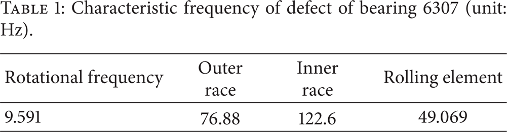
In this paper, bearing 6307 was adopted to conduct the simulation. According to the formula of characteristic frequency of one defect [16], the calculation of the characteristic frequency of the bearing is shown in Table 1. The radial force acting on the bearing is 50 N, and the rotational speed of the output shaft is 1500 r/min. The initial angle of defect is 290°.
Characteristic frequency of defect of bearing 6307 (unit: Hz).
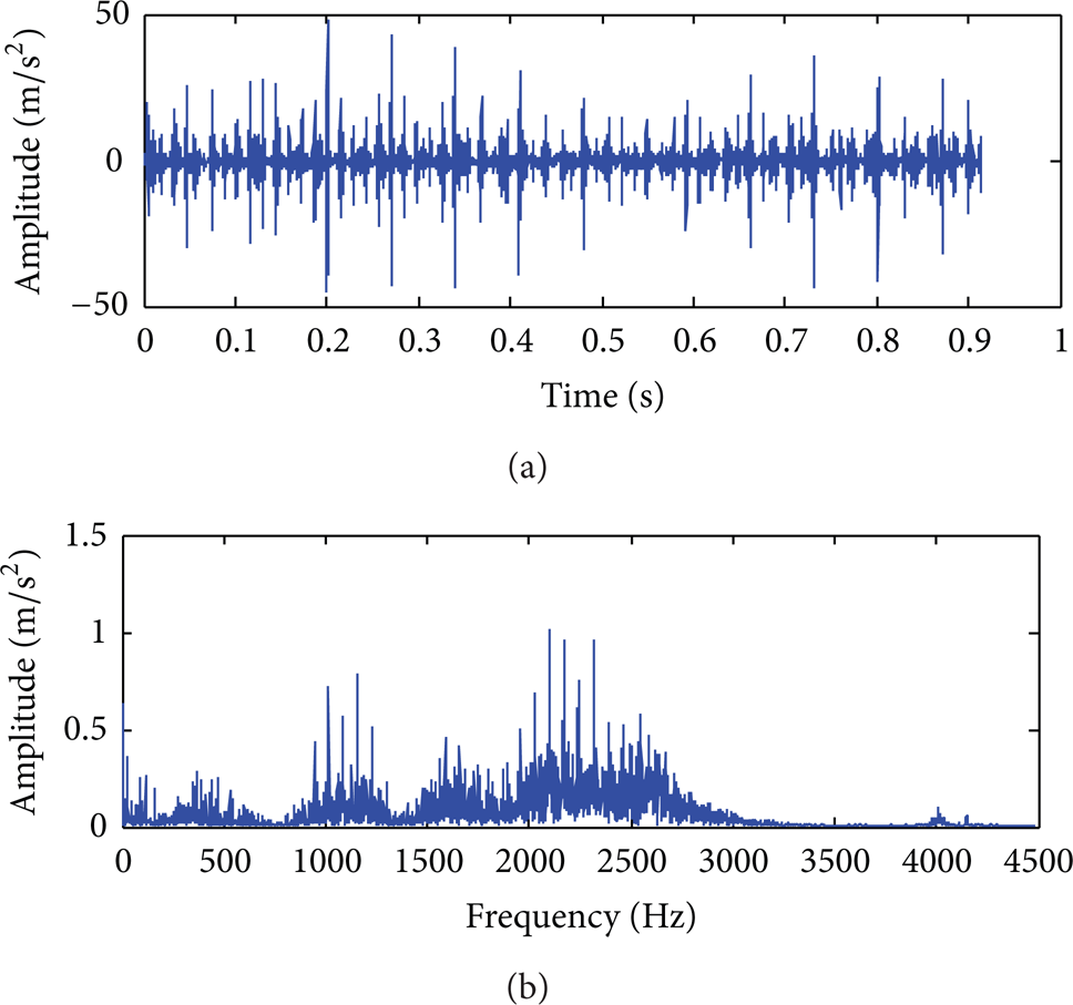
In this section, the crack is first simulated as the local fault. Figures 7(a) and 7(b) show the time-domain waveform and frequency spectrum of the simulated vibration signal of outer race defect, respectively. Figure 8 is the envelope spectrum. It can be seen from Figure 7(a) that when defect occurs to the outer race of bearing, the ball moving over the defect would produce an impact vibration. Hence the time-domain signal during outer race defect is a series of attenuation vibrations of high frequency impulse, with the damage period of outer race being 0.013 s. Meanwhile, the characteristic frequency of defect of the outer race and its multiple frequencies are shown in the envelope spectrogram in Figure 8. This corresponds to what is stated in [17]: when there is a single damage spot on the outer race of the rolling element bearing, its envelope spectrogram is a series of discrete spectral lines. These lines gradually decrease with the increasing amplitude of frequency, with the characteristic frequency of the defect of the outer race as an interval. The accuracy of the proposed outer race defect model and the simulation signals of the defect of the outer race are verified theoretically.

(a) Time-domain waveform and (b) frequency spectrum of simulation signals of outer race with defect.

Envelope spectrogram of simulation signals of outer race with defect.
Figures 9(a) and 9(b) are the time-domain waveform and frequency spectrum of simulated vibration signals of the defect of inner race, respectively. Figure 10 is its envelope spectrum. The vibration response caused by inner race defect is a series of impact vibrations with different amplitudes, showing as sinusoidal modulation in Figure 9. The time interval between two impacts is 0.0084 s, which is exactly the reciprocal of characteristic frequency of the defect of the inner race. According to the envelope spectrum in Figure 10, the rotational frequency 24.26 Hz of the bearing and its frequencies doubled and tripled can be found together with the frequency component of 122.2 Hz and its frequency doubled (245.4 Hz). Furthermore, around these two frequencies, sideband, whose bandwidth is shaft frequency, that is, 24.3 Hz, appears. 122.2 Hz is very close to the characteristic frequency of the defect of the inner race with the frequency of 122.6 Hz in Table 1. This frequency could be regarded as the characteristic frequency of defect, with an error of 0.32%, which is within the permissible range. This corresponds to the statement in [17]. That is, the envelope spectrum of inner race is featured by the spectral lines whose amplitudes gradually decrease at multiple frequency of each order for the defect of the inner race. In addition, taking multiple frequency of each order as the center, there are modulation spectra whose interval equals to circular frequency on the two sides of the center. Moreover, when the amplitude of modulation spectrum is greatly different from the characteristic frequency of defect of each order, it gradually decreases. This verifies the accuracy of inner defect modeling and simulation signals of the defect of the inner race.

Simulation signals of defect of inner race: (a) time-domain waveform and (b) frequency spectrum.

Envelope spectrogram of simulation signal of defect of the inner race.
Figures 11(a) and 11(b) are the time-domain waveform and frequency spectrum of the simulated vibration signal of the defect of the rolling element, respectively. Figure 12 is the envelope spectrum. According to Figure 11(a), when the single-point damage occurs to the rolling element, the vibration response signal is similar to that of the inner race, which is also a series of impact vibration signals with different amplitudes. Rotational frequency of the rolling element and its multiple frequencies can be found in the envelope spectrogram in Figure 12 as well as the characteristic frequency of the defect of the rolling element and its multiple frequencies. Moreover, near the multiple frequency of each order of the latter, there is a sideband whose bandwidth is the rotational frequency of the rolling element. This corresponds to [17]. That is, when the single-point damage occurs to the rolling element, its envelope spectrogram is a series of spectra lines with the multiple frequency of each order for the characteristic frequency of the defect of the rolling element as the center. Thus, the accuracy of defect modeling and simulation signals of the rolling element is verified.

Simulation signal of the defect of the rolling element: (a) time-domain waveform and (b) frequency spectrum.
Envelope spectrogram of simulation signal of defect of the rolling element.
4.2. Experimental Verification
In order to better verify the accuracy of the established nonlinear vibration model of single-point defect of the bearing, 6307 bearing defect test rig was used to get experimental data in the laboratory. The experimental system is composed of the bearing experiment table, HG3528A data acquisition unit acceleration sensors, and a laptop. The bearing test rig (Figure 13 and Figure 14) has a three-phase asynchronous motor ① that is connected to a spindle equipped with a rotor ④ through a flexible coupling ②. The spindle is supported by two 6307 bearings; ③ is the normal bearing; and ⑤ is the bearing that has different single-point pitting faults. The motor speed is 1500 r/min, the larger diameter of the bearing D = 80 mm, the smaller diameter of the bearing d = 35 mm, the number of rolling elements Z = 8, and the contact angle is 0.

Bearing defect test rig.
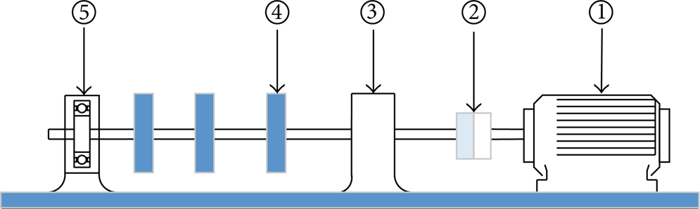
An illustration of the test rig: ① three-phase asynchronous motor, ② flexible coupling, ③ normal bearing, ④ spindle rotor, and ⑤ faults bearing.
Figures 15 to 18 are the time-domain waveforms, frequency spectra, and envelope spectra of the experimental signals of outer race and inner race defect.

Experimental signals of outer race defect: (a) time-domain waveform and (b) frequency spectrum.
Both experimental and simulated time-domain waveform exhibit the basically same periodic characteristics as shown in Figures 7(a), 9(a), 15(a), and 17(a), which shows more background noise in experimental data. It is noticed that several resonances responses due to the defect are excited both in experimental and simulated signals as shown in Figures 7(b), 9(b), 15(b), and 17(b). Resonant frequency bands are concentrated at different location, but the behavior and the excitation pattern are quite similar in both measured and simulated signals. Note the similarities in the envelope spectra and its harmonics are very clear as shown in Figures 8, 10, 16 and 18, thus denoting the accuracy of the vibration model.

Envelope spectrum of experimental signal of outer race defect.
Experimental signals of inner race defect: (a) time-domain waveform and (b) frequency spectrum.

Envelope spectrum of experimental signals of inner race defect.
4.3. Improvement Analysis of Defect Depth Function
In Section 3.3, it is proposed that when the defect shapes are different, different defect depth functions should be adopted. Figure 19 shows the comparison chart of vibration response of bearing under one impact when the constant value and the piecewise function are adopted to represent the defect depth. Blue response signal in the figure is the defect depth c d expressed by the constant value. The red one is the defect depth c d expressed by the piecewise function. The vibration amplitude of the latter is smaller than that of the former. This is because, in the case of the former, the ball gets in contact with the defect from the beginning, and the defect depth mutates to the maximum c d . However, in the case of the latter, the defect depth increases gradually instead of sharp mutation. Hence, no impact of the mutation will happen, and the vibration amplitude is small. By comparing Figure 15 to Figure 7 and Figure 17 to Figure 9, it can be seen that the vibration amplitudes of the experimental signal are all smaller than those of the simulation signals, indicating that the defect depth expressed by the piecewise function is closer to practical situation than that by the constant value. The accuracy of the improved defect depth function is verified.
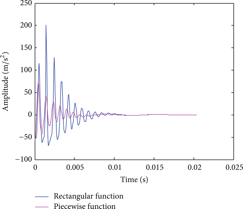
Comparison of vibration response with the defect in piecewise function and constant value, respectively.
5. Conclusion
On the basis of Hertz contact theory, the nonlinear contact force of the bearing was obtained through the contact deformation of the ball. Meanwhile, the factors of lubricant and slide of the ball were also taken into account. A nonlinear vibration model of rolling element bearing with 5-DOF was built. Additionally, when the bearing has single-point defect, the ball rolling over the defect will release some deformation related to the defect depth. Through this relation, the single-point defect model of inner and outer races of bearing and the ball was set up.
Dynamic differential equation of the defect vibration model was numerically solved and the single-point defect of the rolling element bearing was simulated by the ode solver in Matlab. The simulation result was theoretically analyzed and experimentally verified. The accuracy of the proposed defect model is thus verified.
When rectangular function, half sine function, and piecewise function were adopted to show the defects of different size and shape, defect depths reached by the ball were obtained, respectively. By comparing these values to the one obtained by simply using the constant value, the former is much closer to the practical situation than the latter.
The single-point defect model of rolling element bearing could provide theoretical basis to the research on the potential condition monitoring and fault diagnosis algorithms of rolling element bearing in the future.
Conflict of Interests
The authors declare no conflict of interests.
Footnotes
Acknowledgments
This work is supported by the National Nature Science Foundation of China (51175007). The authors are grateful to the editors and anonymous reviewers for their helpful comments and constructive suggestions.