
Abstract
Articulated caterpillar robot has various locomotion patterns—which make it adaptable to different tasks. Generally, the researchers have realized undulatory (transverse wave) and simple rolling locomotion. But many motion patterns are still unexplored. In this paper, peristaltic locomotion and various additional rolling patterns are achieved by employing sinusoidal oscillator with fixed phase difference as the joint controller. The usefulness of the proposed method is verified using simulation and experiment. The design parameters for different locomotion patterns have been calculated that they can be replicated in similar robots immediately.
1. Introduction
The Almighty God created many chain-type creatures such as caterpillar, snake, and earthworm. By utilizing their inherent special structure, they can adapt to various environments through multiple locomotion patterns [1, 2]. For instance, a caterpillar can move in transverse-wave motion to run fast or peristaltic motion to sneak through a narrow hole.
The robotics community has been trying to make artifacts to exploit the movement mechanism of these versatile animals. Many specially designed caterpillar robots have been realized. Besides, the modular self-reconfigurable robot (MSRR) composed of many building blocks can be used to construct diverse types of robots, including caterpillar robot. Several architectural groups are classified according to the geometrical arrangement of MSRR units: chain-type, lattice-type, and hybrid-type [3, 4]. Chain-type and hybrid-type robot fits for application of coordinated locomotion.
Transverse-wave locomotion is realized on many articulated chain-type caterpillar robots, as in [5–11]. In these studies, different kinds of transverse-wave forms are employed, including sine-based wave. But peristaltic motion is not realized on articulated caterpillar robots. Only robots utilizing special material like SMA (shape memory alloy) or special structure that mimic the stretch characteristics of caterpillar and earthworm [12–17] realize this motion pattern. Besides, many implemented rolling motions based on chain-type robot are hand-planned [17] and lack generality.
Transverse-wave and peristaltic motion can adapt to different environments, but to the best of our knowledge no researcher has yet achieved both two motion patterns in articulated chain-type robot. In this paper, simple sinusoidal oscillator with fixed phase difference is employed as the joint controller for achieving transverse-wave and peristaltic motion. Additionally, multipattern rolling motion like ellipse, triangle, and other polygon rolling is planned using the same controller. Figure 1 illustrates some motion patterns suggested in this paper. Motion patterns from top down are transverse-wave motion similar to caterpillar and millipede; peristaltic motion like earthworm; and various rolling patterns beyond the capability of animals like armadillo.
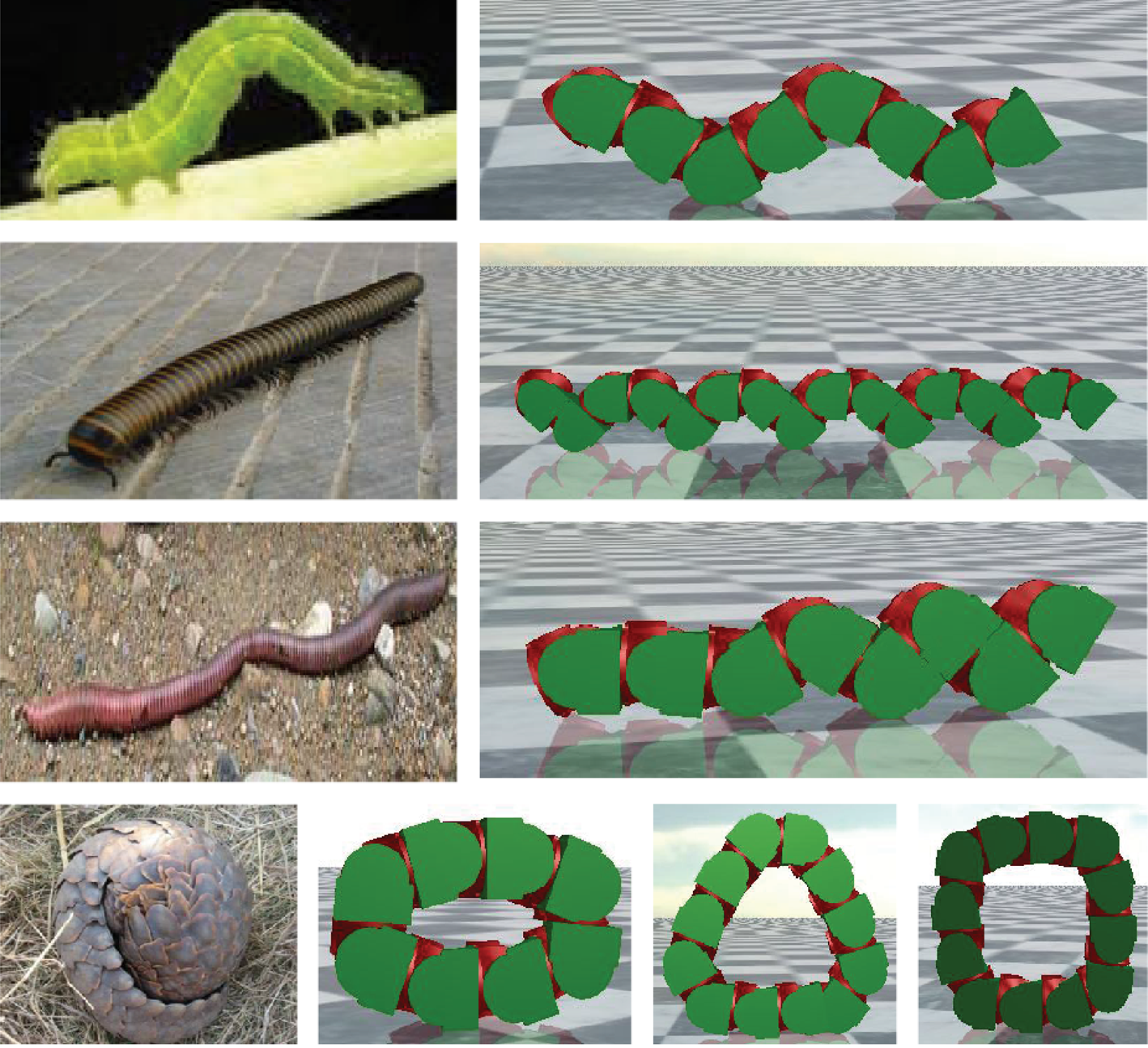
Multipattern locomotion examples.
This paper is organized as follows: Section 2 introduces the caterpillar robot model and its simple controller. Section 3 presents the details of unified planning method for many bionic motion patterns. The experimental results are shared in Section 4. Discussion and future work are presented in Section 5. Finally Section 6 concludes the paper.
2. Caterpillar Robot and Simulator
2.1. Caterpillar Robot
Caterpillar robot, also known as “worm-robot” or “snake-robot,” is an articulated chain-type robot. Its joint axes are perpendicular to its motion direction and parallel to ground. Our investigated caterpillar robot is composed of UBot modules [18, 19], which are hybrid-type MSRR. Figure 2 shows kinematics model of UBot module and caterpillar robot. Each UBot module has two rotary degrees of freedom. Each joint can rotate ranging from −90° to 90°. For caterpillar robot, each module uses only one joint perpendicular to body line from head to tail. It can be recognized as a planar linkage mechanism for analyzing its kinematics.

Kinematics model of UBot module and topology of composed caterpillar robot.
2.2. Controller
Sine-based controller, model-based controller, and CPG (central pattern generation) are often employed to generate rhythmic locomotion for robots. Model-based controller relies on careful analysis and is often piecewise function to keep motion shape. Corresponding model should be carefully designed for certain motion patterns. Examples like triangular wave and trapezoidal wave can be seen in [16, 20]. CPG-based controller is very useful for smoothing gaits transition which depends on communication between modules. If just using CPG-signal without communication coordination, we do not see any advantage in controlling modular robot compared with sine-based controller.
Sine-based controller is easy to implement and can mimic lots of rhythmic motion patterns. In this paper, sine-based controller with certain phase-lag is used on each module; see (1). Offset, amplitude, and phase difference are the same for all the modules. Thus only three design parameters need to be designed: Offset, A, and Δϕ. Consider

where i is module ID and ID increases from head to tail. Offset is oscillatory center of joint angle. A is signal amplitude relative to Offset. Δϕ is the phase difference (or phase-lag) between adjacent modules. Thus joint signals are the same with an identical phase difference. A variety of novel motion patterns can be achieved by manipulating the three parameters.
2.3. UBotsim Simulator
To quickly verify the effectiveness of the proposed strategy, a dynamics simulator is required. Many leading MSRR researchers have developed their own simulator to customize the analysis and evaluation. A newly developed 3D dynamics simulator UBotsim is used to test the method. It is based on PhysX engine and OGRE (object oriented graphics rendering engine). Figure 3 shows a screenshot of UBotsim. A parameter panel is designed to tune planning parameters, which is strictly related to the joint controller (1).
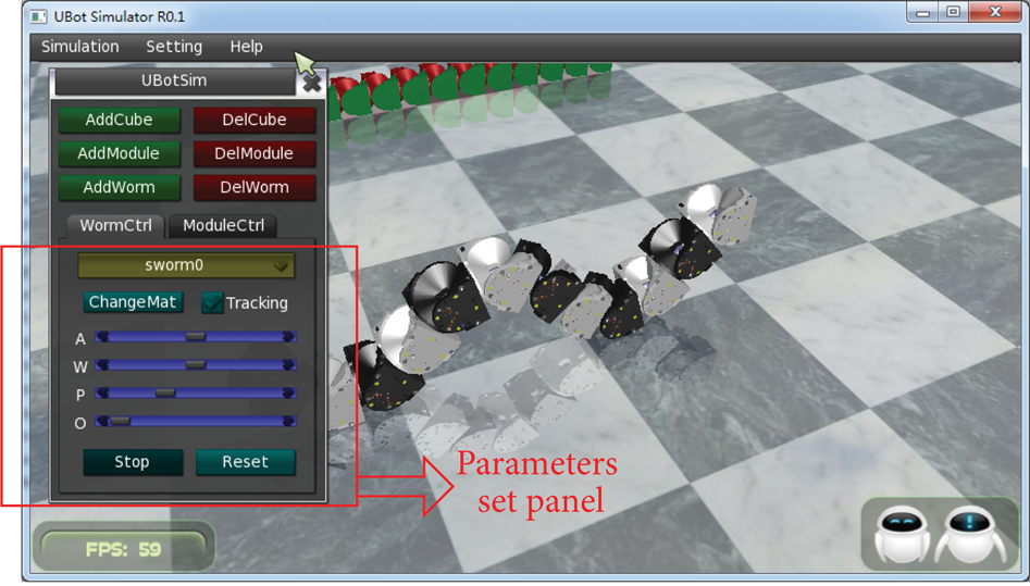
UBotsim—3D dynamics simulator.
3. Planning of Multiple Bionic Motion Patterns
3.1. Wave Patterns
In wave motions patterns, drive signal vibrates at the joint offsetwhich is always set as 0°.
3.1.1. Undulatory Motion Like Transverse Wave
In this pattern, robot shape looks like a sine curve during motion procedure (as shown in Figures 4(a), 4(b), and 4(c)). The phase difference Δϕ is determined by the number of modules in a complete waveform. Suppose there are m modules in a waveform (here count modules on head and tail of a complete waveform as 2; below is the same); the equation can be achieved as Δϕ = 2π/(m − 1). In other words, Δϕ determines the number of modules in a sine-waveform. If Δϕ is identical, the greater the amplitude A is, the higher the waveform height will be.
Locomotion mechanism of caterpillar robot in sine-waveform.
Figure 4(d) shows module has displacements both in horizontal and vertical directions. When right grounding module is replaced by another module, the robot moves a distance of s. There are m − 1 replacement processes in a period of time T. Consequently, when m is the same, the higher the waveform is, the faster the robot runs. Here the robot speed can be written as
The waveform resembles a sine curve if m is big. But considering the geometry and load capacity of actual module, there should be less than ten modules in a complete waveform (it varies for different robot). To make the replacement of grounding modules successful, there should be more than four modules in a full waveform.
According to the above analysis, motion planning method for caterpillar robot in sine-waveform can be set as

Two types of sine-wave locomotion when m takes different values are discussed below.
Caterpillar-Like Locomotion. This locomotion has obvious arches. To simulate a caterpillar, there should be certain number of modules in a full-waveform. In this pattern, the emergence of crest and trough is inevitable. Figure 5 illustrates the simulation screenshot that a caterpillar robot composed of 16 modules moves in transverse wave. The shape of the robot looks like the caterpillar. The parameters are set as A = 30° and Δϕ = π/4 (m = 9).

Caterpillar-like locomotion of 16-module robot.
Millipede-Like Locomotion. If m = 4 (Δϕ = 2π/3), the number of modules in a complete waveform is fewest. In this situation, waveform does not resemble the sine curve. The number of grounding modules is at its maximum. Robot movement looks like a millipede. As it is unable to shape a high arch, amplitude A can be set to the maximum to increase motion speed. Figure 6 is a simulation screenshot of millipede-like locomotion when A = 90°.
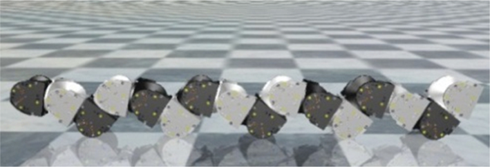
Millipede-like locomotion of 16-module robot.
As the amplitude increases, waveform height will also increase. This may lead to collision between modules. An instance for A = 80° can be seen in Figure 7. A question is what the biggest value of A is for specific m. In numerical simulation of kinematics, if any distance between module centers at time t is less than the threshold 1.414*Module-Length, corresponding A is recognized as the biggest amplitude for corresponding m. This condition guarantees that collision would not happen throughout motion procedure.
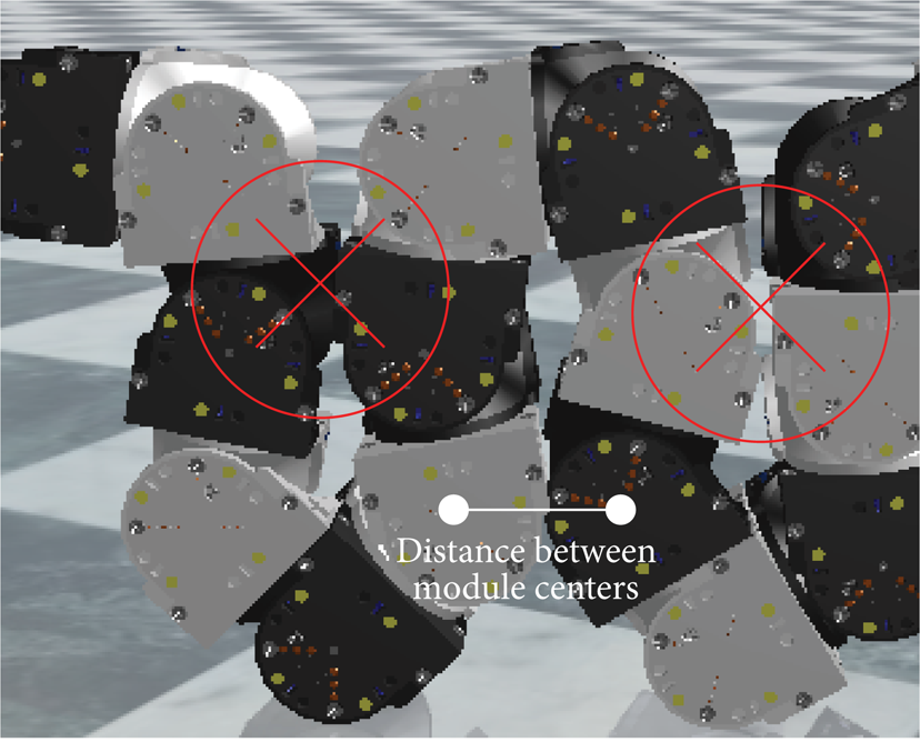
Collision example.
To make the motion process stable, the ratio between wave-height h and wave-length λ should be small, as shown in Figure 8. If the ratio is too small, robot locomotion is not efficient and robot moves slowly. Combining stability and speed, amplitudes located in
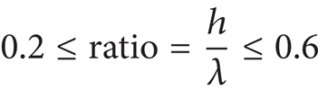
are set as preferred amplitudes scope.
Waveform parameters.
The biggest and preferred amplitudes are calculated using numerical simulation. This is implemented in MATLAB as follows. Firstly, set the metrics of corresponding biggest and preferred amplitudes. Then set coordinates of module ID0 as (0, 0) and compute each module's coordinate in time t (t ∈ [0, T]). According to the coordinates information, we can calculate whether corresponding amplitude fulfills the metrics condition. Here evaluated amplitude values are integers from 0° to 90° for the sake of reducing computation time.
Figure 9 illustrates the results; red line is the biggest amplitude. Other lines represent biggest amplitude when ratio is less than a specific number. Combining the design formula (2), this can be a reference graph for planning sine-wave locomotion for series of caterpillar robot.

Amplitude design reference in sine-waveform motion.
3.1.2. Peristaltic Motion Like Longitudinal Wave
If Δϕ = π, the robot just expands and contracts its body because joint angles of adjacent modules are opposite. The robot expands its body when all joint angles are 0° and contracts its body when all joints are at amplitude (± A). But the whole body cannot move.
If 2π/3 < Δϕ < π, segment of adjacent modules can also expand and contract because adjacent module angles are approximately opposite. Meanwhile there are both expanding and contracting segments across the whole body. As time passes, expanding segment and contracting segment swap states to make robot move like a longitudinal wave.
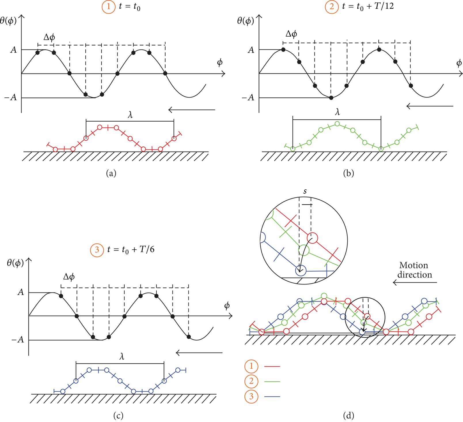
Figure 10 shows joint angle and robot shape states at two time instants when Δϕ = 11π/12, A = 90°. When t = t0, the neighborhood segment of joint angle equal to 0° (blue area) is in expanding state, and center distance of adjacent modules projected in motion direction is large and shapes the sparse part of longitudinal wave. The area of joint angle equal to − A° (red area) is in contracting state, center distance of adjacent modules projected in motion direction is small, and this segment shapes dense part of longitudinal wave. When t = t0 + T/4, joint of 0° rotates to A° and joint − A° to 0°; expanding and contracting states switch. Dense part is useful for support robot and sparse part for transfer modules. This is a little analogous to the peristaltic motion of earthworm.

Peristaltic locomotion mechanism of articulated caterpillar robot in longitudinal waveform.
The module whose joint angle is at ± A is the center of dense part and the module whose joint angle is at 0° is the center of sparse part. In a period of T, a module can be the center of dense and sparse part twice. Modules between adjacent dense (or sparse) centers create a complete longitudinal waveform. The phase difference of two adjacent dense (or sparse) centers is π. Suppose there are m modules in a complete waveform. This is accumulated by m − 1 controller deviation of Δϕ from π; that is, (m − 1)*(π − Δϕ) = π. Consequently, peristaltic motion design formula is achieved as

The larger the amplitude A is, the denser the contracting part will be. Owing to the wave height is small, amplitude A could have a bigger value without concerning about module collision. To make a robot move in complete waveform, m should be less than the robot module number. When m is larger than 6, the longitudinal effect becomes apparent.
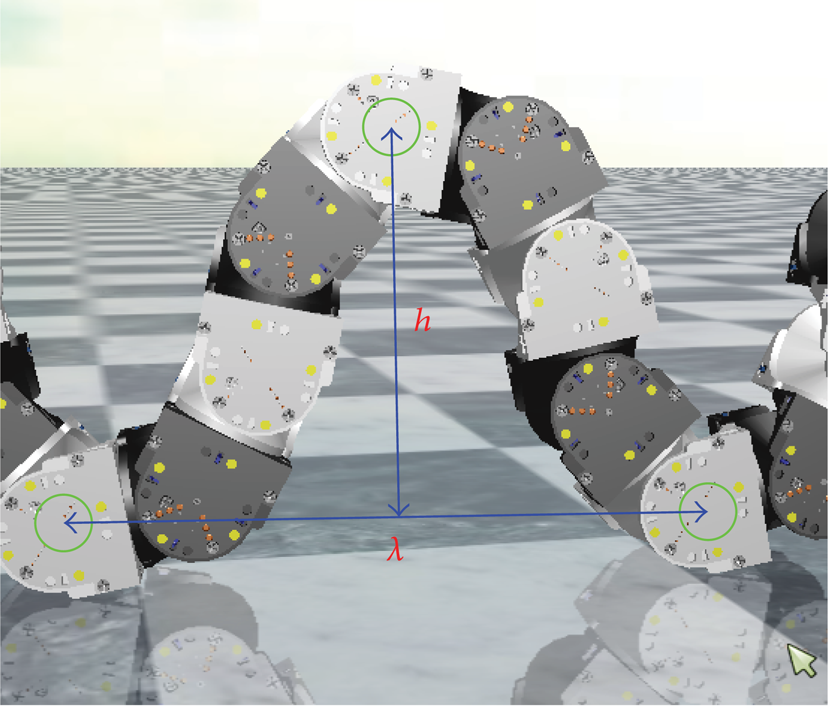
Earthworm-Like Locomotion. An earthworm can move forward by stretching its special body structure, as shown in Figure 11(a) [21]. Using above method, this type of locomotion can be simulated in articulated chain-type robot, as shown in Figure 11(b). The simulation screenshots are a half-T motion when A = 90° and Δϕ = 11π/12. It can be seen that the robot moves by alternately exchanging dense part and sparse part just like the earthworm.
Peristaltic mechanism of earthworm [21] and a simulation based on 16-module articulated caterpillar robot.
3.2. Closed-Loop Rolling
Technical artifacts can surpass locomotion abilities of natural creatures; for example, a caterpillar robot can roll in a loop. The caterpillar robot composed of UBot MSRR modules can form a loop by connecting head and tail module. More than five modules are needed to make a loop suitable for motion. In a rolling loop, the sum of exterior angles must be 360°. Figure 12 illustrates the exterior angles of a polygon. Joint angle shapes the exterior angle.
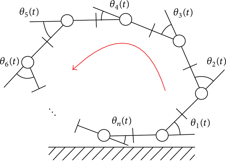
Conceptual model of locomotion in closed-loop type.
To keep the loop closed during the locomotion, joint angles must obey the following formula:

The expression value in the braces should be zero all the time. Then (6) can be drawn as follows:

where [n/2] is an integer less than or equal to n/2. Consequently, design formula of rolling pattern driven by sine oscillator is:

If m = 2, robot shape looks like an ellipse. In this pattern, the larger A, the lower the robot center of mass. Figure 13 shows an example of motion shape when A increases. Here A is 0°, 22.5°, and 40°, respectively.
If m > 2, robot shape looks like a polygon of m edges. Maximal m is determined by n. In m-edges loop, the bigger A is, the more concave the edge will be. But the robot center of mass almost stays the same. Figure 14 shows a few screenshots of robot in polygon shape. Here A = 33.75°. Triangular shape is more realistic considering the height and touch-ground area of the robot; that is, triangle is more stable.

Elliptical states correspond to different values of amplitude.
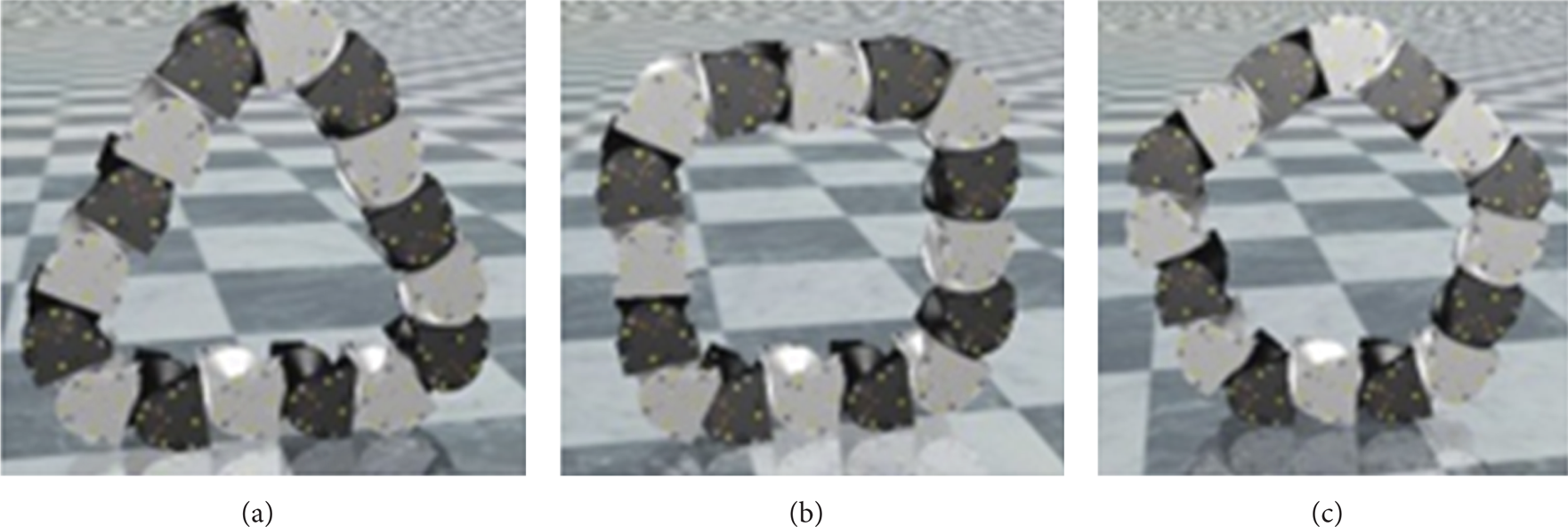
Rolling in polygon shape.
To avoid module collision, amplitude cannot have a bigger value, such as 90°-Offset, in some cases. Figure 15(a) shows an example of collision when A is 45° (here 90°-Offset = 67.5°). Figure 15(b) is the analysis of linkage kinematics based on virtual fixed joint. During the motion process, the distance from joint x to joint 1 must satisfy formula (8). Here x is module ID. Consider

where L is the length of module-edge.

Collision example and collision analysis.
Using numerical simulation, maximum amplitudes correspond to number of modules and polygon edges are calculated. Here maximum module number is set as 20. If number of edges m ≥ 4, maximum amplitudes is 90° − Offset. Figure 16 shows maximum and preferred amplitudes when m ≤ 4. Value of A is recommended to have the same value as Offsetif permitted. That makes the polygon edge similar to a straight line. If A is bigger than Offset, polygon edge shapes a concave curve; otherwise it forms a convex one. Concave curve and a straight line are more stable.
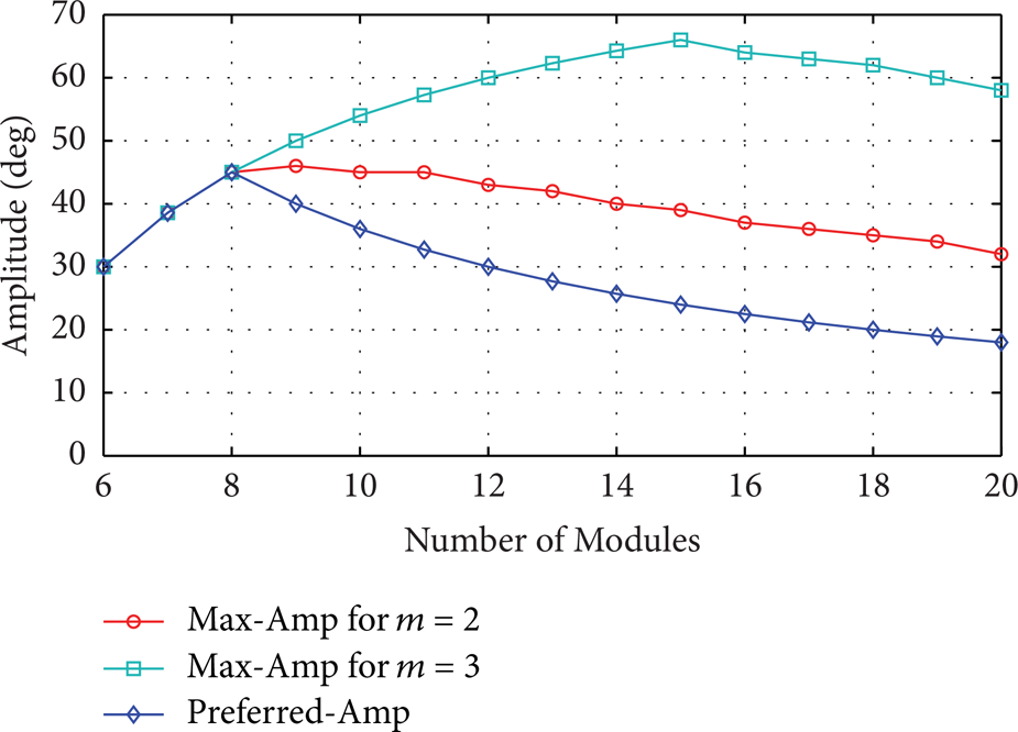
Amplitude references for motion in ellipse and triangle.
4. Experiment
4.1. Hardware
UBot MSRR is employed to verify aforementioned proposed method. As shown in Figure 17, the system is composed of a computer, relay-board, and basic modules. UBot has two kinds of basic modules: active and passive. Active module can attach to passive module using mechanical connecting mechanism mounted on link-face. Diverse configurations may be constructed including simple caterpillar robot.

UBot MSRR experiment system.
In an experiment implementing open-loop gaits, angle instructions should be generated by discretizing joints trajectory and mapping virtual module ID to real module ID using the computer. Then the angle instructions are sent via a relay-board through wireless communication. Module joints rotate by following planned angles. This way, the robot can move in a specific pattern coordinately.
4.2. Testing of Multipattern Locomotion
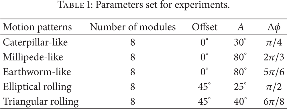
This section verifies the proposed method experimentally for bionic caterpillar-like, millipede-like, and earthworm-like locomotion, as well as beyond nature elliptical rolling and polygon rolling locomotion. The sine-function period of all the experiments is set as T = 4 s. Other experimental parameters are listed in Table 1. For rolling pattern, it is easy to fall down when number of modules is too large. Here we use 8-module loop for the demonstration. A few simulation and experimental videos can be seen in the Supplementary Material available online at http://dx.doi.org/10.1155/2014/259463.
Parameters set for experiments.
4.2.1. Caterpillar-Like Locomotion
Figure 18 shows the experiment screenshots and position changes of body-center. Solid points in Figure 18(b) represent X-Y coordinates at time t (t is integer for 0 to 20). Displacement in Y-direction results from the geometry feature of UBot module and uncertainty in real world. In 20 s, the robot moves about 0.43 m. It can be seen that caterpillar robot moves stably and smoothly in sine-waveform.

Experimental screenshots and body-center changes of caterpillar-like pattern.
4.2.2. Millipede-Like Locomotion
Figure 19 illustrates the locomotion procedure. The robot moves forward about 0.46 m in 20 s. Pictures show that the robot has many grounding modules. Its waveform is low and the motion is stable. As there are many grounding modules, the locomotion process is more like a millipede.

Experimental screenshots and body-center changes of millipede-like pattern.
4.2.3. Earthworm-Like Locomotion
The experiment screenshots of earthworm-like are given in Figure 20. The robot moves forward about 0.34 m in 20 s. The sparse part and dense part of robot exchange in the motion process. This process is like the stretched motion of earthworm. This demonstrates that peristaltic motion can be realized in articulated chain-type robot. This locomotion pattern and above millipede-like pattern are very suitable to restricted environment.
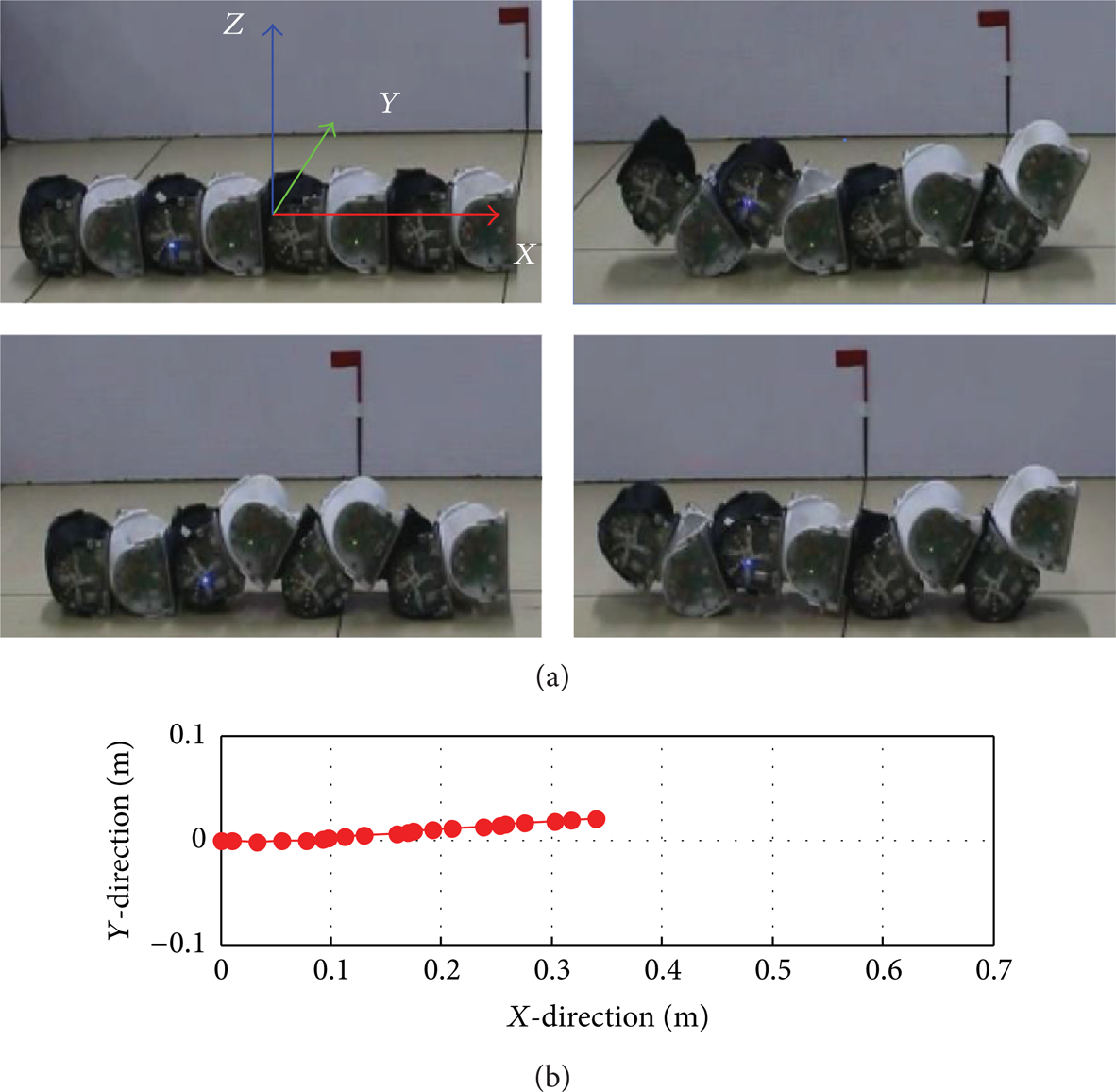
Experimental screenshots and body-center changes of earthworm-like pattern.
4.2.4. Elliptical Rolling Locomotion
Experimental screenshots are shown in Figure 21. In 20 s, the robot rolls about 0.71 m. The robot rolls in a static way. It propels forward through the deformation of the loop. The locomotion trajectory is not straight due to the geometrical characteristic of UBot module.

Experimental screenshots and body-center changes of elliptical rolling pattern.
4.2.5. Triangular Rolling Locomotion
For polygon rolling motion, triangular shape is more stable. Its locomotion procedure is illustrated in Figure 22. The robot rolls forward about 0.47 m in 20 s. It can be observed that the shape of robot resembles a triangle. Same as above static rolling, it also propels forward by deforming the loop. This pattern and above rolling pattern are very suitable for fast motion in a planar environment by enlarging angle speed.

Experimental screenshots and body-center changes of triangle rolling pattern.
5. Discussion and Future Work
All motion patterns, in this paper, are planned in open-loop; that is, the shape of the robot during motion procedure is focused. Testing the performance of different patterns depending on environmental conditions is very important to make it applicable. It is also essential to investigate the control strategies for keeping and switching motion patterns using sensory information such as angle-sensor and infrared-sensor. These studies will enhance the robot's capability and adaptability. That will be our future work.
The UBot MSRR module used to compose robots has two degrees of freedom (DOF). The exploration of its motion capabilities to realize additional locomotion patterns is also a meaningful work.
6. Conclusion
A simple scalable sinusoidal oscillator is successfully employed for implementing diverse bionic locomotion patterns including caterpillar-like, millipede-like, and earthworm-like motions. Diverse rolling patterns are also demonstrated using the same oscillator. The effectiveness of method is verified through simulations and experiments. The main contribution of this paper is the broadening of motion patterns for chain-type robot. Moreover, preferable design parameters (calculated through numerical simulation) can be replicated in other analogous robots immediately.
Conflict of Interests
The authors declare that there is no conflict of interests regarding the publication of this paper.
Footnotes
Acknowledgment
This research is supported by the National Natural Science Foundation of China (60273316).