
Abstract
Damages of a large spiral bevel gear drive as used in heavy industry typically affect the pinion. Even if the gear still could be used, the complete pair has to be changed. This leads to long off times, high costs, and unnecessary waste. This paper applies a recent design technology for spiral bevel gears to the production of a replacement pinion for the sake of energy saving, reduction of costs and off times, and for the realization of green engineering. The process involves the following steps. First, the real tool surface of the gear is measured by a CMM. Based on the new design method, the tooth surface of the mating pinion is derived from this discrete point cloud. In order to improve the meshing performance, the resulting surface of the pinion is modified in the third step. Finally, the pinion is produced on a CNC machining center. In contrast to other approaches, none of these steps needs the parameters of the special machine tool defining the original gear pair. It is worth noting that our technology can also be profitable to gain more freedom in the design of new gear pairs.
1. Introduction
Spiral bevel gears are widely used in large, heavy machinery and equipment. Often manufactured with special machine tools, they are commonly used in pairs and, thus, usually are not interchangeable. Although the concept of “equal strength” is adapted to the design of spiral bevel gears, the pinion is often worn earlier than the gear. In this case, the pair has to be replaced even if the gear still could be used. Besides the caused waste, the long off time of the affected machinery and the very expensive production of large spiral bevel gears leads to high costs. Now it is possible to manufacture these gears’ complicated tooth surface on multiaxis control and multitasking machine tools [1, 2]. Therefore, it is quite natural to ask for a possibility to produce a pinion for the residual gear by a universal CNC machine tool.
Some research has been done to remanufacture large bevel gears. Using micromachining process finishing techniques, Ames [3] presents a method to repair high-value spiral bevel gears for rotorcraft. Tsuji et al. [4] introduced a method for manufacturing a replacement pinion for an existing large-sized skew bevel gear pair using multiaxis control and multitasking machine tool.
While the reverse engineering of the conjugate surface of the existing gear is quite simple (cf. Section 2 below), the usual techniques for the optimization of the gear contact (see [5–10] and the references given there) rely on the correction of the parameters of the special machine tool. Moreover, with the exception of a few approaches (e.g., [10]), both the gear and the pinion are modified. Therefore, an application of these techniques within the context of reverse engineering is quite difficult.
The present paper introduces a technology for the design of a replacement pinion which is based on the real tooth surface of the existing gear only. In particular, the parameters of the special machine tool are not needed for the design and the construction. The designed replacement pinion can be manufactured on a universal CNC machining center. The approach involves the following five steps.
The real tooth surface of the gear is measured by a 3D-coordinate measuring machine.
Using a new approach to the theory of gearing (see [11] or Section 2.2), the tooth surface of the mating pinion is computed from the measured point cloud of the gear tooth surface.
Based on the discrete digital points of the pinion tooth surface derived in (2), modify the surface in order to improve the meshing performance of the real gear drive by precontrolling the contact area [12].
Use the software IMAGEWARE to derive the precise model of the pinion tooth surface from the modified discrete data of the pinion.
Use five-axis CNC machining center and CAM technology to realize the pinion NC machining, including planning the CNC machining process, generating the tool path, and making postprocessing.
Actual cutting and rolling check experiments indicate that the technology presented in this paper is an effective way to remanufacture large spiral bevel gears. It is worth noting that our technology can also be profitable to gain more freedom in the design of new gear pairs.
2. Gear and Mating Pinion
2.1. Rotations
For the following, one needs some basic knowledge on the group SO(3) of rotations and its applications in Mechanics; see, for example, the book [13] of Bullo and Lewis. Here, we give a very brief review only. First, define the so-called hat-operator by putting

The following relations will be used frequently:
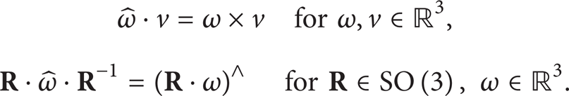
The inverse of the hat-operator will be denoted by “∨”.
Let

is a rotation with axis ℝ·ω and angle t; (3) is called the formula of RODRIGUES. A short computation shows that
2.2. Measurement of the Surface of the Existing Gear
A crucial step for the design of the new gear drive is the precise measurement of the tooth surface of the existing gear. To this end, a 3D-coordinate measuring machine is used to measure sufficiently many points of the active flanks of the tooth surface. While it is sufficient to have the data of 45 points for the purpose of an estimation of the error of the surface, one is faced with substantially higher requests here. In particular, the measurement should meet the following conditions: (1) the measurement paths are chosen in direction of the length of the tooth, (2) the measuring scope comprises the tooth with exception of its root, and (3) the density of the measured points is as high as effectiveness allows.
It is convenient to measure the normals of the surface, too. Alternatively, one can use standard methods (which are based on local least square fittings) for the estimation of the normal vectors. In any case, the result of the current step consists of a point cloud g(r, s) ∈ ℝ3, where r = 1,…, rmax; s = 1,…, smax, together with the corresponding normal vectors n(r, s).
2.3. Computation of the Mating Pinion
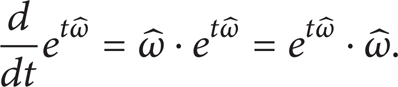
Suppose that the points g(r, s) of the gear are given with respect to a coordinate frame which meets the following conditions: (1) the axes of the gear and the pinion intersect in the origin, (2) the axes have unit directional vectors as follows:
see Figure 1. Moreover, let μ be the constant ratio of the angular velocities of the gear and the pinion.

Installation of the gear and the pinion.
Here, only a rough survey of the computational method can be given; a more detailed treatise is contained in [11]: suppose that the point g(r, s) of the gear is in contact with the point p(r, s) of the pinion at a certain instant t = t(r, s). We derive the following equation:

and, consequently,

The right hand side of the latter equation describes the movement of the gear with respect to a coordinate frame fixed to the pinion; the corresponding body velocity of the gear is

As the relative velocity ω(t) × g(r, s) at the contact point has to be perpendicular to the normal n(r, s), one derives the equation of meshing as follows:

A short and easy computation leads to the following result. Put

and, moreover,

Then,

yields the following form of the equation of meshing:

The latter equation can be solved explicitly for t ∈ (− π/2, π/2); if

then (13) has precisely the solutions

The corresponding point p(r, s) of the pinion is given by

Therefore, one obtains the mating pinion as a point cloud

together with the instants t(r, s) at which the gear and the pinion are in contact at g(r, s) and p(r, s).
2.4. Computation of the Instantaneous Contact Lines
At every instant t0, the pinion and the gear are in contact along some curve λ(t0) on the surface of the pinion. In fact, this so-called instantaneous contact line

can be viewed as the image of the level set of the function (r, s)↦t(r, s) under the parameterization p. A first picture of the contact lines can be derived by rounding the instants t sufficiently rough, see Figure 2.

Instantaneous contact lines on the tooth surface of the pinion.
More sophisticated techniques from computer imaging produce better results (with or without adding new points to the tooth surface); we will not go into details here.
In what follows, we require that the two instantaneous contact lines λ(t1) and λ(t2), where t1≠t2, do not have points in common. In fact, this is guaranteed provided that inequality (14) holds for all (r, s).
3. Tooth Surface Modification of the Pinion
Modification of the tooth surface is a highly active field of research. Most of the existing approaches are based on traditional machine tools or CNC free-form gear cutting machines. The new flank correction method presented here uses the discrete point cloud of the pinion and the instantaneous contact lines computed in Section 2.4 only; machine parameters or knowledge on the tool are not needed.
Usually, the designer of a gear drive has some ideas for the position, the direction, and the size of the contact area. These ideas can be carried into effect by appropriate choices of the influencing factors within the following modification method.
3.1. Design of the Path of Contact
Choose some point P0 on the tooth surface; this point will be in the middle of the contact area. The corresponding surface normal will be denoted by N0. Let E be a plane through P0 having N0 as one of its directional vectors. The path of contact ζ (which will be the middle of the contact area) is the intersection of E and the tooth surface, cp. Figure 3.

Path of contact (yellow) and contact line (green) through P0.
By sliding the plane H along the instantaneous contact lines and by rotating it around the tooth surface normal in P0, one gets two degrees of freedom for the choice of ζ, which in turn determines the direction and the position of the to be designed contact area. Figure 4 shows different positions of ζ. For example, under the condition of light load, one may choose ζ near to the toe of the pinion. The tilt angle between ζ and the instantaneous contact line through P0 has great influence on the coincidence degree of the gear drive.

Different positions and tilt angles of the path of contact.
The intersection curve ζ is given in the discrete model of the pinion only. Using interpolation techniques, one may achieve the following: if the instantaneous contact lines λ(t1) and λ(t2) intersect ζ, and if t1 < t′ < t2, then λ(t′) intersects ζ, too.
The only restriction (which can be made precisely now) on the choice of the path of contact is the following: if ζ meets an instantaneous contact line λ(t) at some point p, then the tangent vectors of ζ and λ(t) at p are not parallel; that is, the curves ζ and λ(t) intersect transversally.
The union of instantaneous contact lines meeting the path of contact forms a subsurface M of the tooth surface. Obviously, one can find a quadrangular mesh for M, together with a discrete parameterization
We point out that the points outside M (the orange points in Figure 5) are not parameterized because the corresponding instantaneous lines of contact do not meet ζ.

Choosing an appropriate discrete parameterization (green, orange lines: instantaneous contact lines, yellow line: path of contact).
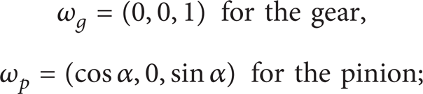
Finally, we introduce distances on the path of contact as well as on the instantaneous contact lines by setting
3.2. Modification Principle
We will modify only the tooth surface of the pinion; the surface of the gear remains unchanged. The points
First, one modifies the points

The magnitudes for the remaining points (i.e., those ones whose corresponding contact lines do not meet the path of contact) are set to the magnitude of the nearest point
We point out that modifying along the path of contact causes transmission errors which can be decreased by controlling the magnitude of the modification. Nevertheless, if the points of ζ remain unchanged, then there will be no transmission error.
Examples for the functions used in the modification process are provided by monomials a·x n (where n is at least 2). In order to gain more freedom in the design, one can use different monomials in- and outside the contact area to be designed. To be more precisely, suppose that the contact area should intersect the path of contact ζ in an arc segment ζ int of arc length 2L c . Recall that the tooth surface modification center is the center of ζ int . If the designer wants to use the modification magnitude h c at the boundary points of ζ int , then one can use the following function:
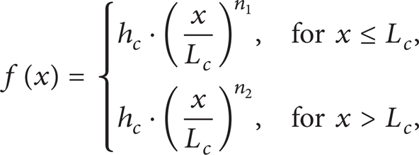
(with different integers n1, n2) to achieve the desired result. Figure 6 provides an example of a function of this type.

Example for one of the functions f(x) defined in (21).
If the points of ζ int should not be modified, then a function like

will do the job. The very same functions can also be used for the modification along the instantaneous lines of contact.
According to this method, the designer gains full control on the size of the contact area by choosing appropriate modification functions. An example is given in Figure 7.

Designed contact areas of different width.
4. Visual Tooth Contact Analysis
By “visual tooth contact analysis,” one understands the method of building a virtual gear inspection machine based on CAD models of gear and pinion. Visual tooth contact analysis can be used in order to check the gears meshing condition.
Gear and pinion were installed on the virtual machine using the same coordinate system. The gear drive was assembled according to certain mounting positions; the only restriction is that the gear and the pinion are in contact (same position vector of the points) and that both surfaces share a common normal at the point of contact. In order to estimate the contact area, one can move the pinion about 0.00625 mm in the direction of the common normal. The resulting intersection is the boundary of some domain of the pinion's tooth surface; this domain turns out to be a very good estimate for the contact area, see Figure 8.

Visual tooth contact analysis.
One obtains a very clear view at the contact pattern before machining the pinion. Therefore, one has the opportunity to make quick adjustments by computer simulation. The method has great benefits for the improvement of the machining efficiency and for shortening the design cycle. In contrast to the traditional situation, less personal experience is needed in this part of the design of a spiral bevel gear drive.
Moreover, visual tooth contact analysis can also be used to analyze a variety of installation errors very easily. In fact, the method can support or even replace the roll test of tooth surfaces. Thus, it shortens the processing cycle and reduces the manufacturing costs.
5. Manufacture of the Mating Pinion
Path planning plays a crucial role for the manufacture of the mating pinion with a CNC milling machine. In order to guarantee the geometric accuracy and the surface quality of the machined surface, removal of volume is done in several processes: (1) the rough cut with several flat end mills, (2) the semifinish cut with several ball end mills, and (3) the finish cut with a ball end mill. In order to minimize the machining time, larger tools are used for the rough and for the semifinish cuts. A process plan is shown in Table 1.
Process planning for gears.

6. Example
In this section, the presented technology is verified by an example which also shows the realization of our methods. Even if the technology is more useful for large spiral bevel gears, we took a gear with pitch diameter about 400 mm for the sake of saving time and energy. The dimensions of the spiral bevel gear are shown in Table 2.
Dimensions of the spiral bevel gear drive.

First, the surface of the existing gear was measured by using a CMM of CARL ZEISS (CONTURA G2), cf. Figure 9, whose probe has a diameter of 1.5 mm. We adopted the scan software for our purposes. The width and the height of the tooth face are approximately 20 × 60 mm. The grid used consists of 200 × 600 points; approximately 70,000 points are used. The measured region is almost as large as the tooth surface of the gear; due to the limitation of the CMM, one cannot measure the edges of the tooth. The scan path was chosen in the length direction of the tooth surface.
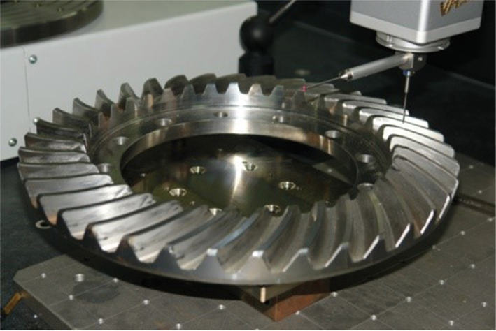
Measuring the tooth surface of gear using CMM.
After measuring sufficiently many points of the gear, the points and the instantaneous lines of contact of the pinion are calculated by the computer, cf. Sections 2.3 and 2.4 for details. Subsequently, the contact area is designed by arranging the path of contact and by adjusting the direction of the path contact. Figure 10 shows the simulation of the contact area done during the modification process.

Simulation of the contact area.
In the third step, the tooth surface is modified from line contact to point contact.
The interaction of the tooth flanks of the gear and the pinion was investigated by simulating the gear drive. Through this one obtains valuable information on the design and on manufacturing.
The CADCAM software UG is used in the final step for process planning (cf. Table 1) and to define the cutting paths on a CNC machining center, see Figure 11. Then, the pinion was produced by a 5-axis CNC machining center, see Figure 12. The subsequent check of the tooth contact pattern was done using a soft marking compound (Figure 13). The results obtained so far indicate a high coincidence between the real tooth contact pattern and the results of the simulation by visual tooth contact analysis, cp. Section 4.
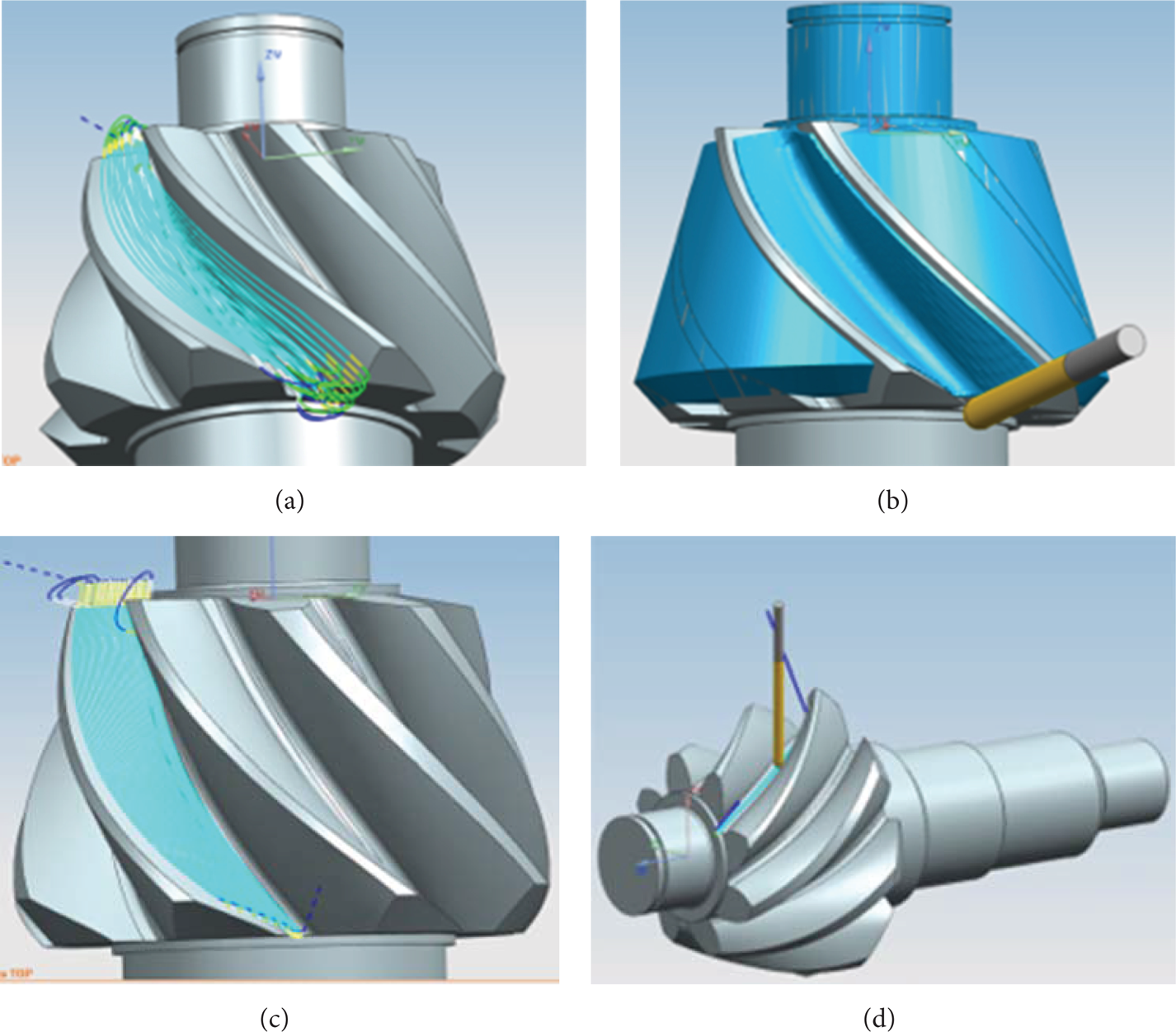
Simulated tooth cutting.
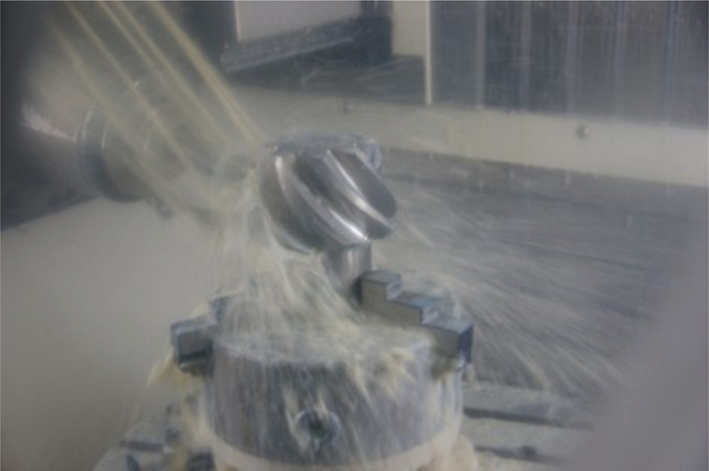
Cutting the pinion on CNC machining center.

Tooth contact patterns.
7. Conclusions
In this paper, a new method for the design of a replacement pinion of a bevel gear drive respecting the existing gear member was proposed. The designed pinion can be manufactured on a CNC machining center. The main results and conclusions of the present investigation can be summarized as follows.
The points of the existing gear are measured by a 3D-CMM. The required density of the point cloud is quite high.
There is no necessity of knowing the parameters of the special machine tool used for the production of the original gear pair.
Using tools from contemporary mathematics, the computation of the discrete model of the mating pinion and the instantaneous contact lines is done by a fast and easy to understand algorithm.
The proposed modification method for the pinion as well as the visual TCA only relies on the geometry of the gear pair given by the discrete model. In particular, solving nonlinear equations is not necessary, whence the methods are easy to understand.
The modification method provides an extensive control of the position, the direction, and the size of the contact area. Therefore, the designer gains more flexibility for the modification and, hence, can realize the required functionality.
It is worth noting that the methods can also be used for the design of new spiral bevel gear drives.
The manufacture of the designed pinion is done on a CNC machining center; only standard tools are used in this final step. In particular, no special cutting or milling machines are needed.
Summing up, the new technology for remanufacturing large spiral bevel gears shows strong potential for the realization of significant production cost savings as well as for minimizing off times. Moreover, it can also be used for the design of new spiral bevel gear pairs.
Footnotes
Nomenclature
Conflict of Interests
The authors declare that there is no conflict of interests regarding the publication of this paper.
Acknowledgments
This research has received financial support from the National Natural Science Foundation of China (no. 51205025) and was supported by the Funding Project for Academic Human Resources Development in Institutions of Higher Learning under the Jurisdiction of Beijing Municipality as well as Funding Project for Academic Human Resources Development in Beijing Union University, for which the authors are very appreciative.