
Abstract
Due to some deficiencies in the existing researches of cutting element wear of polycrystalline diamond compact (PDC) drill bit and to reduce the wear rate of cutting element of PDC bit, accurately illustrate the effect of tooth-distributing angle on cutting element, and improve the service life of PDC drill bit, we use the geometry knowledge of PDC drill bit and establish the torsion vibration model of PDC drill bit, solve and analyze the model, and at last analyze the effect of tooth-distributing angle on the rule of cutting element wear by using the wear theory.
1. Introduction
The results of polycrystalline diamond compact (PDC) drill bit rock breaking are affected by many factors, including the weight on bit (WOB), rotation speed, torque, which are related to load, and the cutters’ density and tooth-distributing angle, which related to structure. According to the coupling relationship between cutters and rock, the failure modes of cutters (as cutting element) are as follows: the rock-breaking volume of blade's central cutting element is small, the main failure mode is wear, and the wear amount is small, while the linear velocity of blade's peripheral cutting element is big and the effective volume of rock breaking is big, and the normal failure mode is wear and the abnormal failure mode is crack. Additionally, the failure mode of drill bit's gauge tooth is also wear.
Aiming at the existing researches for wear failure of PDC drill bit's cutting element by experts and scholars at home and abroad, the literature [1] thought the transient of PDC drill bit's processing technology (tool cutting, fast cooling, and pressure removal) was a major reason for the formation of microcrack and led to premature failure of the drill bit. The literature [2] described the structure and parameter designs of PDC drill bit in depth and how to improve the service life and reduce the wear rate of PDC drill bit. According to some materials used by PDC drill bit, the literature [3] carried out a detailed study and the author believed that the main reasons for the failure of cutting element were wear resistance and poor impact toughness of WC-Co carbide which could not withstand harsh working environment at bottom hole. The literature [4] thought, in the process of drilling, the vibration of drill string, especially transverse vibration, was the root of premature failure of PDC drill bit. The literature [5] thought the failure of PDC drill bit was mainly due to repeated impact load which was the main reason for crack initiation and growth and was ultimately leading to failure.
Due to the difference between the above researches and the real failure, the paper has studied the blade's peripheral cutting element with the biggest wear amount. Based on the dynamics and tribology, we have analyzed the effect of the drill bit's tooth-distributing angle on the law of cutting element wear. Given the WOB, speed, and torque as load parameters and the bit blade number and cutters’ density as structure parameters, we have established the mathematical model of the wear rule affected by tooth-distributing angle, which is based on the dynamic wear theory. The load in the analysis model is the dynamic load of bit drilling process, which is more consistent with the cutting element's real load in the rock-breaking process, and more accurately reflects the effect of tooth-distributing angle on the dynamic wear rule. The results of the model can obtain the quantitative indicators which have a guiding significance to the optimization on tooth distribution of PDC drill bit.
2. Calculation Model
Rock cutting by PDC drill bit's cutting teeth at bottom hole is actually a problem of cutting element's oblique cutting. As for PDC drill bit, the geometry model is the foundation of the study of the cutting mechanics and dynamics of PDC drill bit, especially in which the changes in the parameters of tooth-distributing angle have a great effect on the force and wear resistance of PDC drill bit. The geometry model is in Figure 1.

Geometry model of PDC drill bit's cutting teeth.
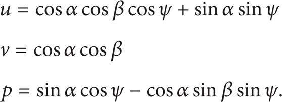
According to the definition of PDC drill bit's geometry angle, assume the coordinate of any point of cutting element (cutter) as w(r, ψ, h c ), where r is the radius of cutter, ψ is the location angle of cutter, h c is the axial distance of cutter's anchor point, ξ is the normal angle of cutter, α is the cutting edge angle of cutter, β is the side rake angle of cutter. According to the analysis and accurate calculation of PDC cutter working angle in the article by Li et al. [6], the normal direction vector of the cutter working surface can be obtained:

where
According to the relationship of the geometric model and coordinate conversion, we have established the computational formula of PDC cutting element's cutting edge angle, front rake angle, side rake angle, and back rake angle. The geometry formula [7] of the cutting edge angle and back rake angle is obtained as

where β k is the cutting edge angle, rad, and the computational formulas of x1, y1, ζ1, ζ2, ζ3 are as

As shown in Figure 2, assume any point in PDC drill bit's cutting element as (x, y), when 0 < y < r; the computational formula of the cutting point is as
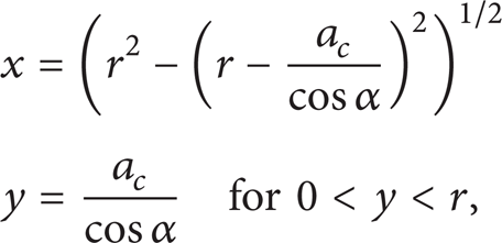
where a c is the cutting depth of compact, mm.
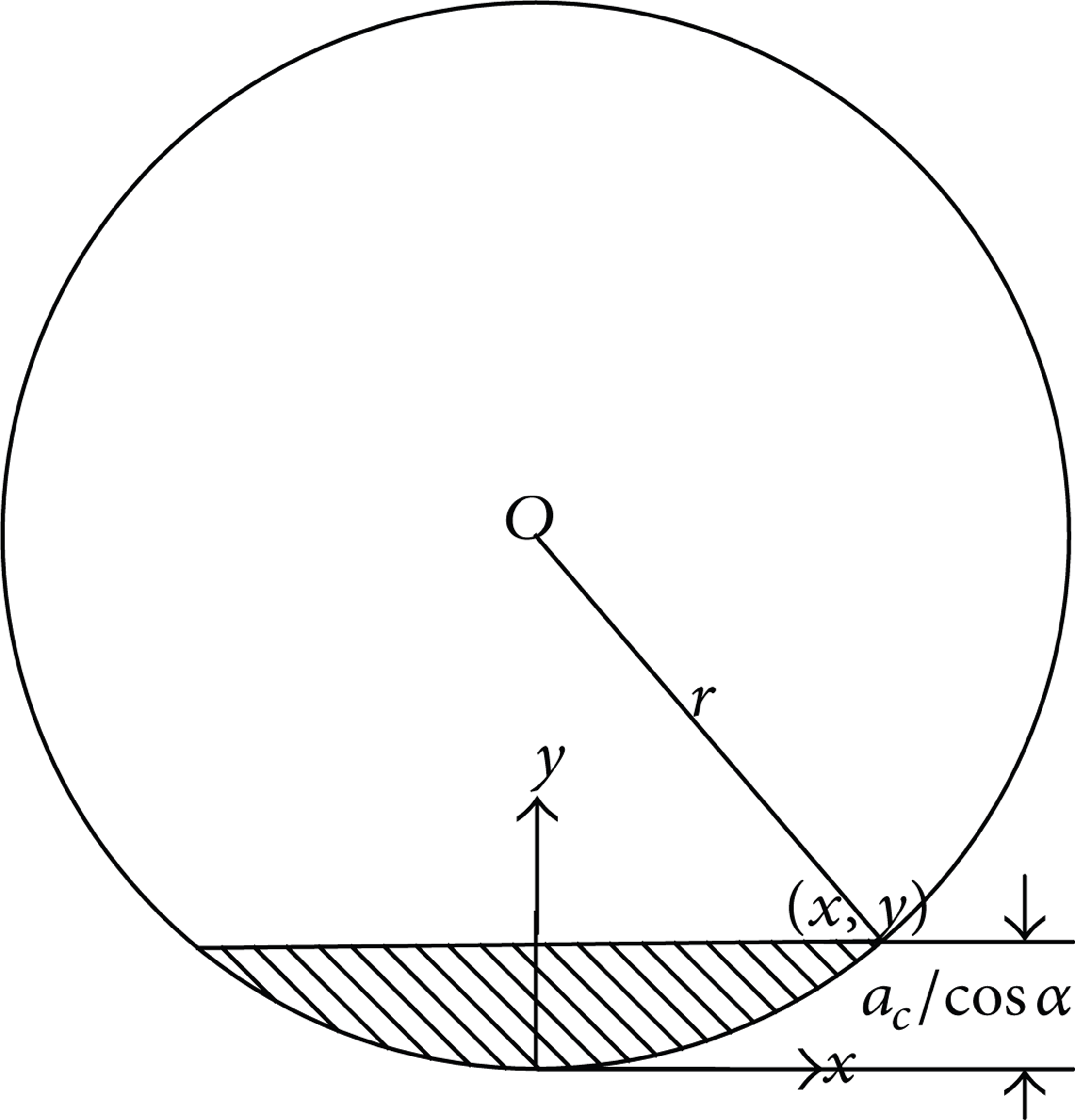
Diagram of PDC drill bit's cutting element.
According to the computational formulas of geometry, the formulas of the effective cutting edge length lccl , cutting arc length L, and cutting area Acutting can be obtained as
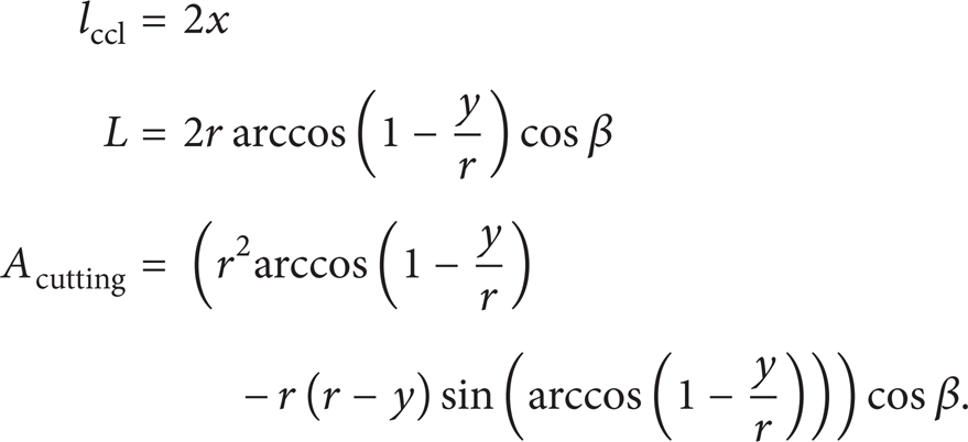
Substituting formulas (5) into formula (6), we can obtain the calculations of the cutting edge cutting, cutting arc length, and cutting area.
In the drilling process of PDC drill bit, the motion of cutting element at bottom hole is extremely complex. Assuming the bit axis coincides with the well center line, the cutting teeth have two main directional motions at bottom hole; one is the rotation motion of cutting teeth round the bit axis, and the other is the downward motion of cutting teeth together with the bit. To facilitate the analysis of torsional vibration of PDC drill bit, we have made some assumptions: the drill string and drill collar are both homogeneous elastomers; the rotation speed of the top swivel plate and the WOB always remain the same. The simplified model of PDC drill bit with dynamics of torsional vibration is in Figure 3.

Dynamic model of PDC drill bit.
Through the dispersed method, we transform the established dynamic system of PDC drill bit with torsional vibration into a discrete system of a limited degree freedom; the differential vibration equation of PDC drill bit can be written as the following matrix form:

where [M] is the whole moment of inertia matrix, [C] is the whole damping matrix, [K] is the whole stiffness matrix, [T(t)] is the whole dynamic torque matrix, {θ} is the whole angle matrix,
In the drilling process, the torsional vibration of drill string and drill collar makes PDC drill bit produce very high dynamic torque at bottom hole. The dynamic torque imposed on PDC drill bit by drill string is T1′(t); at this point the dynamic torque and drill string's positive torque T1(t) on swivel plate are the same, while rock will produce resistance torque T2(t) to PDC drill bit; at this point the dynamic torque T(t) on the drill can be expressed as
According to formulas (7) and (8), we can work out the rotation angle θ (rad) and rotation angular velocity

The motion of PDC drill bit at bottom hole is partly from the downward motion of the bit; namely, the axial linear velocity Val (mm/s) of the drill bit at bottom hole is as

where R j is the rate of penetration (ROP), (m/h).
At this point, the absolute linear velocity V (mm/s) of PDC drill bit at bottom hole is

According to the relationship between rotation speed and linear velocity, the rotation speed of PDC drill bit at bottom hole can be calculated as

where N is the rotation speed of PDC drill bit, (rad/min).
In oil drilling, the failure of PDC cutting element due to normal wear accounts for most of its failure. According to the principle of nonlinear dynamical system, the wear process can be divided into three stages, namely, the stages of self-organization, chaos, and instability, corresponding to the three stages of running-in wear, normal wear, and sharp wear in the expression of tribology. If the effect of dynamic on the wear of PDC compact had not considered, it would not reflect the true wear situation of PDC bit. As a result, the wear equation based on torsional vibration is very important for the study of cutting element wear.
In the drilling process of PDC drill bit, we assume the time of cutting rock as t, substitute the drill speed obtained by formula (12) into the wear volume formula, and obtain that [8]

where τ is the cutting element wear strength, N/m2, p is the pressure distribution density, N/m, l is the effective cutting edge length of cutting element, mm, μ is the friction coefficient between cutting element and rock, and δ is the distance from wear parts to the center of drill bit, mm.
The pressure distribution density p in formula (13) can also be expressed by the following formula:
where F d is the PDC axial pressure, N, L is the arc length produced when the cutting element cuts rock, mm, D is the diameter of PDC drill bit, mm, and φ is the caster angle, (°).
Substituting formula (14) into formula (13) and dividing by time t, we obtain the cutting element's volume wear rate by the tooth-distributing angle of PDC drill bit based on torsion vibration:

where v t is the cutting element's volume wear rate, mm3/h, and C p is the hydraulic coefficient.
In the design of PDC drill bit, with the increase of the diameter, the wear linear velocity will increase, and the rock-breaking volume of the cutter is also on the rise. Assuming that the cutting depth is 1 mm and substituting formula (12) into formula (15), we obtain the relationship between the linear velocity, diameter, and volume wear rate:

Integrating formula (16), we obtain the computational formula of the back rake angle:

3. The Analysis of Examples
Using the geometry equation of drill bit's tooth-distributing angle and according to the given example parameters, we have calculated and analyzed the relationship between the cutting edge angle and back rake angle, as well as the effect of the back rake angle on the cutting area and cutting arc. Then we have analyzed the dynamics of PDC drill bit in the process of drilling and put the solved bit speed into the solving theory of cutting element's wear rate to analyze wear. The partial example parameters are in Table 1 and the results are in Table 2, Figures 4 and 5.
Specific parameters.
Calculations of the back rake angle, cutting edge angle, and effective length of cutting edge.


Relationship between the cutting edge angle and the back rake angle.
Relationship between the cutting edge angle and the cutting area, cutting the arc length.
Through the analysis of Figures 4 and 5, there is a close relationship between the back rake angle, cutting edge angle, effective cutting edge length, cutting area, and cutting arc length. From the values of the back rake angle and cutting edge angle, with the increase of back rake angle, the cutting edge angle and effective length of cutting edge both increase, but we found that the increase of cutting edge angle is not obvious; namely, the increasing rate of cutting edge angle is about 300 times that of cutting edge angle, and known by the way of curve fitting, they have a relationship of an exponential function. With the increase of the cutting edge angle, the cutting area and cutting arc length decrease obviously; namely, the tiny change of back rake angle has a great effect on them. What is more, the decreasing speed of the cutting area is far greater than that of the cutting edge angle; namely, the change of the back rake angle has a greater effect on the cutting area. By the curve fitting, we find that the above figure curves all accord with the distribution characteristic of sine function, but seen from the fitting accuracy, the fitting between the cutting edge angle and cutting length is more accurate. Due to the increase of the back rake angle, it makes the effective cutting edge length increase and the cutting area and cutting arc length decrease, which significantly reduces rock-breaking efficiency and ROP. As a result, it will have no high efficiency of rock breaking.
According to the computational formula of dynamics and the specific parameters in Table 3, the rotation angle and vibration angular velocity of PDC drill bit at bottom hole can be obtained in the process of drilling, as well as the speed of PDC drill bit under the common action of the rotary motion and downward movement, as shown in Figures 6, 7, and 8.
Specific parameters.


Vibration corner of PDC drill bit.

Vibration angular velocity of PDC drill bit.

Relationship between PDC drill bit's rotation angular velocity and speed.
From Figure 8 the following is shown: with the increase of angular velocity, the speed of PDC drill bit is also on the rise, basically in a linear distribution. And in the process of drilling, the strong vibration of PDC drill bit at bottom hole will have a great effect on the PDC drill bit performance, service life, tooth-distributing angle of PDC drill bit, and cutting element wear.
According to formula (15), we can cognize the effect of PDC drill from the center to the periphery of blade on the wear rule of cutting element. Assume the cutting arc length as 7.9012 mm; the result is shown in Figure 9. By determining the volume wear rate of each part of cutting element, we can obtain the back rake angle and cutting edge angle, which provide the reference for the optimization of tooth distribution. At the same time, we also need to consider the tooth-distributing blade numbers, diameter, and other parameters together to achieve the purpose of optimizing the rock-breaking performance. Taking the cutting element at the gauge diameter, for example, we assume that the WOB is 80 KN; the axial pressure that is distributed in each cutting element and the other parameters used in computational analysis are shown in Table 4.
Specific parameters.


Distance from the wear parts to the center of drill bit and the cutting element.
In Figure 9, the cutting element's volume wear rate v t and the distance δ from the wear parts to the center of drill bit have a direct relationship; with the increase of δ, v t is also on the rise, which is in a linear distribution. This phenomenon shows that the rock-breaking volume and wear amount of bit's central cutting element are small, while those of blade's peripheral cutting element are large. As a result, the study of largest wear amount of blade's peripheral cutting element is reasonable in this paper.
Substituting the data in Table 4 into formula (16), we get the calculations of cutting element's wear rule affected by the back rake angle, shown in Figure 10.

Relationship between the back rake angle and wear rate of cutting element volume.
According to the relationship between the back rake angle and front rake angle, the above listed data and the formula of the volume wear rate of PDC cutting element based on torsion vibration, we can obtain the result of cutting element's wear rule affected by the cutting edge angle, shown in Figure 11.

Relationship between the cutting edge angle and wear rate of cutting element volume.
According to the results of Figures 10 and 11, in the analysis of cutting element's wear rule affected by tooth-distributing angle, the value of tooth-distributing angle ranges from 0° to 90°, because the selection of the angle is not greater than 90° in the actual processing application. With the increase of the back rake angle of PDC drill bit, the cutting element's volume wear rate decreases significantly. The cutting edge angle has a very complex effect on the volume wear rate of PDC cutting element. Seen from Figure 11, with the increase of cutting edge angle, the volume wear rate of cutting element decreases, but the decreasing trend is nonlinear. At the same time, combined with Figure 3, with the increase of back rake angle, the cutting edge angle is also on the increase, when the inclination increases and the cutting element's volume wear rate decreases, and the increase of the cutting edge angle is also bound to decrease, verifying the correctness of Figure 11. As a result, we should choose a large tooth-distributing angle to reduce the volume wear rate of compact, which improves service life of drill bit, but the unduly large back rake angle will change the cutting direction and reduce cutting efficiency and service life of bit, so how to choose a suitable tooth-distributing angle will have a great effect on the performance of PDC drill bit and its service life.
4. Field Data Comparative Analysis
4.1. Calculation Results and Experimental Verification
According to the corresponding numerical parameters, results, and optimization of tooth-distributing parameters by each performance index from drill design, we have processed four experimental bits with different tooth-distributing angles as shown in Table 5. In order to verify the correctness of calculations better, we have done experiments in the third section of drill 1 well and second section of drill 2 well in an oil field where the wellbore is 311.2 mm, the drilling rig is ZJ70J, the mud pump is F-1600, the cylinder liner diameter is 150 mm, the drilling fluid density is 1.02 g/cm3, the viscosity is 60 s, the sediment concentration is 0.3%, the new degrees of the four experimental bits are 100% and 30%, respectively, when the four drills go into and out of the wells; the other specific experimental parameters are in Table 6. In the field test, we record ROP at all times and use the laboratory equipment including the vibration meter, sensor, and speedometer to test PDC drill bit and then import the test data into the special software, deal with the data, and analyze the speed of PDC drill bit and cutting element's volume wear rate. The experiment results are in Figures 12 and 13.
Experimental data of drill bit.

Experimental parameters in the field.


Speed of PDC drill bit.

Comparison chart between the calculated and testing values.
4.2. Comparative Analysis
We can know, through the experiment, the lithology is mainly composed of sandstone and shale; the main compositions of sandstone are quartz with rich black mineral, grain structure, mediocre separation, subrounded particle, argillaceous cement, densification, and hard characteristic; shale contains part of silty clay with developing lamellation, densification, and brittle and medium-hard characteristic.
According to the degree of drill wear, we find that drill 1 drill wear is the most serious, the gauge teeth have wear, the drill teeth wear is very serious, and the outer row of teeth has many broken teeth. Drill 4 wear is the lightest, the gauge teeth basically have no wear, the drill teeth wear a little, and the outer row of teeth has no broken teeth. Drill 2 and drill 3 are worse than drill 4; the outer row of teeth has the phenomenon of broken teeth, but compared with drill 2, drill 3 drill wear is worse and the phenomenon of broken teeth of the outer row of teeth is a little more.
We get that the speed and cutting element's volume wear rate of PDC drill bit, the same as the drill bit in the calculation parameters, basically agree with the experimental results which verify the rationality and accuracy of the theoretical calculation.
The test speeds of the PDC drill bit in the process of the experiment are not stable, but a certain degree of vibration is normal, because the physical properties, chemical properties, and soft and hard degree of rock are different, which will certainly produce different degrees of resistance to PDC cutting element, so it makes PDC drill bit have a certain degree of instability in the bottom-hole movement.
We can see from Figure 13 that there are still some errors on the calculated and experimental values of the cutting element's volume wear rate of PDC drill bit affected by the back rake angle and cutting edge angle; the error range within five percent is acceptable in engineering. The error factors are various; for example, we did not take into account the effects on drill string friction by the wall in the theoretical analysis. In the process of analyzing torsion vibration, the drill bit axis is often supposed to coincide with the well centerline, but in the real drilling, it is impossible that the axis of PDC drill bit and the well centerline coincide. We take the vertical well, for example, and think that a variety of factors such as no deflection angle lead to errors in the process of drilling.
5. Conclusions
Compared with the existing research methods in the references which consider cutting element wear just from the point of statics or the whole view of bit, our paper has analyzed cutting element wear affected by PDC tooth-distributing angle based on torsion vibration, which makes computational accuracy improve by about 10%∼20%. From each point of affecting PDC tooth-distribution, we know that the back angle and cutting edge angle have the most serious effect on PDC cutting element wear; this conclusion has certain reference significance to how to reduce wear failure of PDC cutting element.
The wear rate of cutting element has a close relationship with not only the back rake angle and cutting edge angle, but also the hard and soft degree of rock; the wear degree of drill 2 should be more than drill 3, but the result is actually on the contrary. What is more, when the drilling parameters and other experimental conditions are the same, the only change is the lithology, which exactly demonstrates that the lithology has an important effect on the degree of cutting element wear.
Due to the comparative analysis of PDC cutting element wear affected by the back rack angle and cutting edge angle, we can know that the effect of back rack angle on the wear rate of PDC cutting element is greater than the cutting edge angle, so how to choose a reasonable back rack angle becomes very important.
Conflict of Interests
The authors declare that there is no conflict of interests regarding the publication of this paper.
Footnotes
Acknowledgments
This work is supported by Open Fund (OGE201403-05) of Key Laboratory of Oil & Gas Equipment, Ministry of Education (Southwest Petroleum University), National Natural Science Foundation of China (51074202, 11102173), and Major Cultivation Foundation of Sichuan Education Department (12ZZ003, no. 667).