
Abstract
Transportation safety of supercritical CO2 pipeline is a key aspect of carbon capture and storage (CCS). For reducing the high pressure in supercritical pipeline when accidental cases arise, man-made release will be applied using chocking process. The downstream parameters of chocking process can be predicted based on the adiabatic process assumption. In the critical chocking process, the critical velocity at outlet is sonic. A chocking pipe can be designed for buffering between different chocking orifices according to the length of turbulence area produced by jetting momentum. For the effect of noise hazard produced by large jetting velocity, a muffler can be applied at the outlet of final stage orifice to atmosphere. For the influence of impurities on the chocking process of anthropogenic CO2 pipeline, the presence of SO2 as an impurity is helpful for increasing the downstream temperatures through the chocking device to prevent the frozen hazard, whereas the presence of N2 as an impurity indicates a lower downstream temperature. The higher initial temperature can prevent the dry ice formation at the outlet of vent pipe when the multistage chocking is applied.
1. Introduction
Carbon dioxide (CO2), produced by fossil fuel combustion from human activity, is the predominant anthropogenic greenhouse gas (GHG) that has led to the gradual increase in the global temperature in recent decades. Carbon capture and storage (CCS) has received much attention as an abatement technology which can eliminate 20%–40% of the global carbon emissions. To help relieve the high cost and energy consumption of CCS, CO2-utilisation has been added to form carbon capture, utilisation, and storage (CCUS). CCUS is a technology wherein captured and purified CO2 is recycled into a new production process rather than directly sequestered. Safe transportation is a key aspect of CCUS as a major technology to reduce CO2 emissions and improve the climate. Pipeline transportation, compared with ship, truck, and railway, has been certified as the optimised choice for gas transportation. It is estimated that there are over 3000 km of pipeline for natural or anthropogenic CO2 transportation in the world [1]. Information and experience from several representative CO2 pipelines show CO2 should be transported as a supercritical or dense phase fluid economically [2].
Safety on high pressure is more important in CO2 transportation of supercritical or dense phase pipeline. When emergencies take place, the blow-down of a supercritical CO2 pipeline will be applied to release the pressure as fast as possible. CO2 is a common inorganic compound. It is a colourless, odourless gas with a density slightly higher than that of air at standard temperature and pressure. The solid particles, commonly known as “dry ice,” will form in the state that the temperature is below the melting line and the pressure is above the sublimation line in the phase diagram. In high-pressure natural gas pipelines, the safety issue is to prevent the hydrate formation upon orifice when the rapid depressurization arises. However, both hydrate formation and dry ice formation will be controlled at where the CO2 fluid chokes. According to the CO2 pipeline specifications [3, 4], the water content of transported CO2 is recommended to be below 500 ppmv (parts per million by volume) to ensure that no free water is present in the CO2 pipeline to avoid hydrate formation and internal corrosion.
Based on the detailed literature review, the dry ice formation can totally block the blow-down valve during the man-made release. Martynov et al. [5] proposed the choked flow model for CO2 at the triple point and described the development of a detailed release rate model for CO2 pipeline, suitable for input to CFD (Computational Fluid Dynamics) near-field and far-field dispersion modeling. Mahgerefteh et al. [6, 7] performed the simulation of decompression for short pipelines and storage reservoirs. Fredenhagen and Eggers [8] considered the vessel blow-down model as a limiting, zero-dimensional, version of the pipeline release model where the momentum of the fluid upstream of the release point is neglected. For experimental investigation of the flow properties of releasing from high-pressure CO2 pipelines, Martynov et al. [5] performed the experimental validation of a three-phase flow model for predicting the transient outflow following the failure of pressurised CO2 pipelines and vessels. Han et al. [9] investigated the flow properties in the jettisoning flow line of a liquid CO2 carrier. The data from the experiments involving pressurised CO2 releases which were carried out at Spadeadam by GL Noble Denton for BP in 2006 [10] and for Shell in 2010 [11, 12] along with other material was transferred into the DNV led CO2PIPETRANS JIP. DNV Software was commissioned by the JIP to undertake a critical review of the data corresponding to horizontal nonimpinging releases to assess its suitability for public release for model validation. Huang [13] investigated the experiments and analyzed the relevant theories on the formation and blockage of CO2 particles in safety valves and downstream pipes. The deposition and melt properties of CO2 particles have been predicted. However, the theories are mainly applied in the design, optimization, and utilization of CO2 safety valve at high pressure. For the influence of impurities on the transportation safety of an anthropogenic CO2 pipeline, Seevam et al. [14] demonstrated the effect of impurities on binary combinations containing 5% impurities with respect to the research on phase diagrams and physical parameters. However, the variation of the parameters in chocking pipe for pure supercritical CO2 and the influence of the impurities on the variation of temperatures and pressures during anthropogenic CO2 release from high-pressure pipelines have not been studied to date.
This paper shows the model for predicting the CO2 parameters and concentrates the variation of important parameters including velocity, kinetic energy, and static pressure in chocking pipe. This paper also discusses the influence of the impurities on the variation of temperatures and pressures when the CO2 chocks. Operational recommendations are provided for pressure man-made release of anthropogenic CO2 pipelines.
2. Methods
Chocking is a phenomenon of abrupt pressure drop using suddenly narrow section. In thermodynamics, the Joule-Thomson effect describes the temperature change of a fluid when it is forced through a valve or orifice while kept insulated so that no heat is exchanged with the environment. Therefore, the variation of temperatures and pressures can be studied at where the CO2 chokes according to the Joule-Thomson effect. When the CO2 flows through the orifice, the heat transfer between the fluid and the environment can be neglected since the fluid flow in narrow section is fast and the chocking distance is relatively short. The assumption that chocking process is the adiabatic process can be applied. To describe the supercritical CO2 flow in chocking pipe, a one-dimensional chocking model will be expressed in this section based on the adiabatic process assumption.
2.1. Critical Chocking Model
Supercritical CO2 is in a fluid state, and the temperature and pressure are above the critical point, that is, 31.1°C and 7.38 MPa. For man-made release of a supercritical CO2 pipeline, multistage chocking will be applied because the high pressure in pipeline cannot be reduced to ambient pressure directly. From the laws of energy, the basic equation describing a one-dimensional chocking flow in pipe may be expressed as follows:

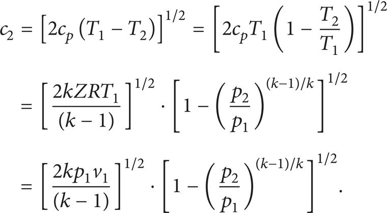
where H1 and H2 are the enthalpies of upstream and downstream correspondingly and c1 and c2 are the flow velocities of upstream and downstream correspondingly. Consider the following:

For c2 in supercritical CO2 pipeline, c1 can be neglected when c1 ≤ 50 m/s. According to the experience of industry, a typical velocity in a pipeline transporting CO2 is considered to be limited between 1 and 5 m/s [15]. Therefore,

For the flowing fluid in adiabatic process, the Mach number (Ma) of which is not very large, the equations are given by


where c p is the heat capacity at constant pressure, p1 and p2 are the absolute pressure upstream and downstream, T1 and T2 are the absolute temperature upstream and downstream, k is the adiabatic exponent which is defined as the ratio of heat capacity at constant pressure to heat capacity at constant volume, Z is the compressibility factor, and R is the universal gas constant. Therefore, the velocity of downstream when the fluid chokes can be rewritten as follows:
The propagation velocity of weak pressure disturbance in compressible fluid is defined as the local speed of sound (c), since

where ρ is the density of fluid. For “p/ρ k = Const” in adiabatic process and “p/ρ = ZRT” (equation of state, EOS), the speed of sound can be rewritten:

where “v = 1/ρ”.
In supercritical CO2 pipeline, the man-made release is performed in a condition that is usually defined as critical chocking. If the back-pressure is the ambient pressure, the downstream rate of CO2 fluid through the orifice will be a maximum. The downstream velocity will be the local speed of sound. According to (7) and (9), the following equation can be drawn:
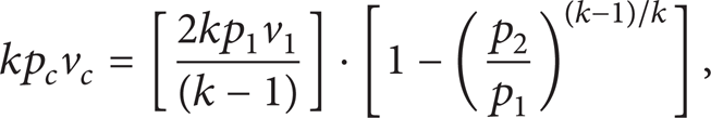
where the subscript “c” refers to the critical parameter, respectively.
The ratio of the minimum downstream pressure to the upstream pressure is denoted as β when CO2 chokes in pipe. Consider the following:

The average value of k for pure CO2 is approximately 1.3. Therefore, the value of β is 0.546. It means that the minimum downstream pressure is dependent on the upstream pressure if chocking arises in pipe.
2.2. Governing Equations of Numerical Simulation
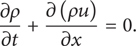
The mathematical model for simulation of chocking process, including conservation of mass, conservation of momentum, conservation of energy, and RNG k-ε turbulence model, can be written as follows.
Conservation of mass is
Conservation of momentum is

Conservation of energy is
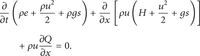
RNG k-ε turbulence model is

where
The pressure values of 8 MPa, 10 MPa, and 13 MPa and the corresponding temperature of 40°C are used as the initial inlet conditions, respectively. The outlet condition is the ambient condition of 0.101325 MPa and 15°C. And the heat transfer condition of pipe wall is assumed as insulation. The velocity, kinetic energy, and static pressure after chocking process in chocking pipe can be simulated based on the algorithm of SIMPLE.
2.3. Downstream Temperature Prediction Model
In chocking pipe of supercritical CO2, the temperature will change with the decreasing pressure as a result of the Joule-Thomson effect. The adiabatic Bernoulli equation is a reasonable application since the heat transfer between the fluid and the environment can be neglected during the CO2 chocks. Consider the following:

According to (1) and (5), the Bernoulli equation can be rewritten as follows:

The enthalpy of real gas is the sum of the enthalpy of ideal gas at constant temperature and the isothermal enthalpy difference:

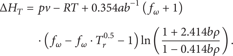
where H0 is the enthalpy of ideal gas at constant temperature and ΔH T is the isothermal enthalpy difference.
The Peng-Robinson (PR) equation of state is recommended for analysis of the properties of supercritical CO2 in pipeline [16]:

where
b = 0.07780RT c ·p c −1,
fω = 0.3746 + 1.5422ω − 0.26992ω2.
The isothermal enthalpy difference can be expressed as follows:
For supercritical CO2, the enthalpy of ideal gas at constant temperature is

The relevant equations and parameters of iteration are showed in Figure 1. According to Figure 1 of algorithm flowchart, the downstream temperature through the chocking device can be predicted using the relation of enthalpy and temperature.

Algorithm flowchart for prediction the downstream temperature through the orifice.
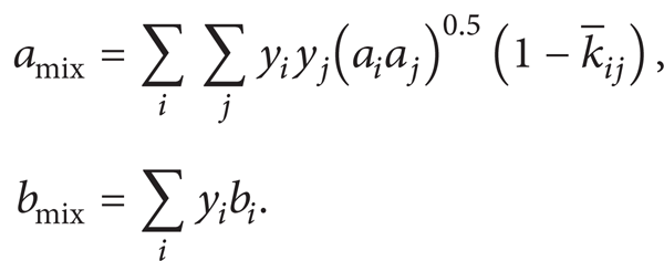
2.4. Mixing Rules
To use the equations of the model for transported anthropogenic CO2, the mixing rules must be selected. There are several different mixing rules available for different component mixtures. The mixture parameters of (19) must be determined separately for mixtures of different compositions. In general, the parameters a and b for (19) are replaced as follows for anthropogenic CO2. These are the most common mixture rules that have been developed from both empirical and theoretical studies [17]. The value of
3. Results and Discussion
The numerical simulation results about variation of the parameters in chocking pipe will be presented. And the influence of impurities on the critical chocking process of supercritical CO2 at different initial pressure will be discussed.
3.1. Variation of the Parameters in Chocking Pipe
For analyzing the process of multistage critical chocking, the numerical simulation is applied to simulate the cases of three stages of chocking of supercritical CO2 using orifice. The variation of important parameters including velocity, kinetic energy, and static pressure in chocking pipe can be presented. A chocking pipe of 1.5 m length and 50 mm diameter is used as the physical model for the initialization of numerical simulation. The geometric structure of physical model is shown in Figure 2. The geometry of chocking pipe is structured based on the real equipment in the laboratory with the length ratio of 1: 1. The CO2 fluid from the trunk pipeline will go into the buffer pipe of 25 cm to make the fluid steady before the first stage chocking orifice. A pipe of 50 cm is applied between different chocking orifices. The CO2 will be emitted to the atmosphere through a pipe of 25 cm after the last stage chocking orifice. The structured grid is used in the whole physical model. And the meshes at the axial line of chocking pipe through orifices are refined to describe the flow in pipe accurately. The contour distribution of velocity magnitude (m/s) at different inlet pressures is shown in Figure 3.

Geometric structure of chocking pipe.

Velocity magnitude (m/s) at different inlet pressures.
According to Figure 3, the critical velocity at outlet is sonic in the critical chocking process. It means that the outlet pressure is dependent on the upstream pressure because the value of k for pure CO2 is constant. According to Figure 3, the velocity at outlet of orifice will peak with the increasing upstream pressure. However, the jettison area of high velocity will be larger after the chocking orifice in chocking pipe with the increasing outlet velocity. Even though the outlet velocity has a maximum speed of sound, the jetting momentum will increase with the increasing upstream pressure. The turbulence area exists on the inwall of pipeline because the fluid is disturbed near the orifice in the jetting and expansion process due to the viscosity of fluid in pipe.
The RANS (Reynolds-Averaged Navier-Stokes) equations are used to describe the turbulent flow process. The k-ε model is a two-equation model which includes two extra transported variables, turbulent kinetic energy which determines the energy in the turbulence and turbulent dissipation which determines the scale of the turbulence to represent the turbulent properties of the flow. The contour distribution of turbulent kinetic energy (m2/s2) at different inlet pressures is shown in Figure 4.

Turbulent kinetic energy (m2/s2) at different inlet pressures.
According to Figure 4, the kinetic energy after chocking which means turbulence intensity will increase with the increasing upstream pressure. And Figure 4 shows the turbulence length after chocking in the pipe will increase when the upstream pressure increases because of the proportional relationship between the stronger turbulence intensity and the larger jetting momentum in chocking pipe. Therefore, the pipe length of nonfinal stage chocking in multistage chocking process is designed based on the flow parameters and turbulence state after chocking to ensure that the parameters at orifice inlet are steady.
Figure 5 presents the variation of static pressure with position of chocking pipe at different inlet pressures. The downstream pressure cannot decrease to the critical pressure and keep steady immediately when the fluid flows from abrupt-contractive section to abrupt-enlarging section. The downstream pressure in chocking pipe will have a small increase and then keep constant because the shock wave will be produced when the CO2 flows through chocking device to abrupt-enlarging section. The location where the static pressure is steady and the turbulence length are corresponding. In the operating process of industry scale, the pressure after chocking may be lower than the calculation value because of the existence of chocking expansion and friction factor. The deviation can be presented using experiments.

Variation of static pressure (Pa) with position of chocking pipe at different inlet pressures.
Based on the analysis on the variation of important parameters including velocity, kinetic energy, and static pressure in chocking pipe, several operational recommendations for the chocking process of pure supercritical CO2 pipeline can be recommended as follows.
In multistage chocking process, a chocking pipe is used for buffering between different chocking orifices. The length of chocking pipe is larger than the length of turbulence area produced by jetting momentum. And the length of chocking pipe can be designed according to the maximum operational pressure of pipeline because the lengths of turbulence produced by different upstream pressures are different.
For the chocking process of different operational pressures in pipeline, the trans-chocking process is applied because the chocking stage is dependent on the operating pressure of pipeline.
For the effect of noise hazard produced by large jetting velocity, a muffler can be applied at the outlet of final stage orifice to atmosphere.
3.2. Influence of Impurities on Supercritical CO2 Chocking
The impurities in transported natural or anthropogenic CO2 will influence the variation of the temperatures and pressures in chocking process. Transported CO2 sources from power plants mainly include nitrogen (N2), oxygen (O2), hydrogen sulfide (H2S), and sulfur dioxide (SO2). To study the variation in CO2 chocking, the binary systems will include 95 mol% CO2 and 5 mol% impurity. According to the calculated results using the model for supercritical CO2 chocking, the downstream temperatures and pressures at different inlet parameters in chocking process are presented in Figure 6.

Influence of 5 mol% impurities on chocking parameters at different inlet pressures.
These figures show the N2 and O2 as impurities and will reduce the downstream temperatures in chocking pipe. H2S as an impurity causes the smallest deviation of the downstream temperatures of the binary system. Conversely, SO2 as an impurity raises the downstream temperatures through the chocking device. Taking the molecular type of impurities into consideration, nonpolar impurity has weak van der Waals force and strong volatility. The nonpolar impurity will make the phase equilibrium of anthropogenic CO2 deviate to the lower temperature direction. The van der Waals force of polar impurity is strong. So, the phase equilibrium of anthropogenic CO2 with polar impurity will deviate to the higher temperature direction due to the induced effect.
According to the analysis of Figure 6, the conclusion can be drawn that the outlet pressures deviate not large each other at different inlet pressures for anthropogenic CO2 with the same impurity. The outlet temperatures at the third stage of chocking are different as a result of the different inlet pressures at constant inlet temperature. The higher outlet temperatures and pressures are dependent on the higher inlet pressures at constant chocking stages. Conversely, the lower outlet temperatures and pressures are a result of the lower upstream parameters.
For the different amount of nonpolar impurity such as N2, the deviation of outlet temperature from that of pure CO2 after the chocking orifice is different. According to Figure 7, the deviation will be larger with the increasing amount of N2 as an impurity. For the different amount of polar impurity such as SO2, the deviation to the higher temperature direction is also different. The deviation of outlet temperature from that of pure CO2 produced by chocking will increase when the amount of SO2 in the binary system increases as presented in Figure 8. And according to comparison of Figures 7 and 8, the deviation of outlet pressure has small difference when the amount of N2 is the same as that of SO2. However, deviation of outlet temperature produced by the existence of SO2 is larger than that produced by N2 as an impurity. The reason for this difference is that SO2 has a similar molecular structure as CO2 and a larger molecular weight than N2. The existence of SO2 in the binary system will increase the molecular weight of anthropogenic CO2 and make the influence of polar impurity on the outlet parameters more obvious. Particularly, the lowest outlet temperature prediction on anthropogenic CO2 chocking and the presented conclusions about the influence of impurity based on the energy laws and mixing rules can be applied in industry-scale chocking operation even though the location of solid particle formation has not been taken into account.

Influence of different amount of nonpolar impurity (N2) on chocking parameters.

Influence of different amount of polar impurity (SO2) on chocking parameters.
3.3. Operation Recommendations for Anthropogenic CO2 Chocking
The dry ice cannot form at the downstream parameters mentioned in above section. However, the low temperature will cause the safety issue of frozen hazard on pipe device such as flowmeter and environment. The low temperature cannot meet the parameter requirement of chocking device if chocking is applied for one more stage.
Several operational recommendations for the chocking of anthropogenic CO2 can be recommended as follows based on the discussion of above figures.
It is necessary to prevent the presence of N2 and O2 as impurities in the anthropogenic CO2 because the presence of them indicates a lower downstream temperature through the chocking device.
The influence of H2S on the downstream temperatures may be negligible. However, the presence of H2S will cause corrosion in the pipe at some water levels. Therefore, H2S as an impurity in transported anthropogenic CO2 must meet the relative requirement.
The presence of SO2 as an impurity is helpful for increasing the downstream temperatures through the chocking device to prevent the frozen hazard.
The higher initial temperature can prevent the dry ice formation at the outlet of vent pipe when the multistage chocking is applied.
4. Conclusion
This study validates the model for predicting the critical chocking of supercritical CO2 and demonstrates the influence of impurities on chocking process of anthropogenic CO2. The conclusions and operational recommendations of chocking process are as follows.
The downstream parameters of chocking process can be predicted based on the adiabatic process assumption.
In the critical chocking process, the critical velocity at outlet is sonic. A chocking pipe can be designed for buffering between different chocking orifices according to the length of turbulence area produced by jetting momentum. For the effect of noise hazard produced by large jetting velocity, a muffler can be applied at the outlet of final stage orifice to atmosphere.
The presence of nitrogen or oxygen as an impurity in anthropogenic CO2 indicates a lower downstream temperature through the chocking device. The influence of H2S on the downstream temperatures may be negligible. However, the presence of SO2 as an impurity is helpful for increasing the downstream temperatures through the chocking device to prevent the frozen hazard.
The higher initial temperature can prevent the dry ice formation at the outlet of vent pipe when the multistage chocking is applied.
Footnotes
Recommendations for Future Work
It is important to validate the transient flow and decompression wave models for the cases of man-made pressure release or accidental leakage by comparing the calculations with experimentally measured data. The College of Pipeline and Civil Engineering in the China University of Petroleum is in the process of conducting the relevant experiments. The research results will be published in a future paper. And the issues of thermodynamics and heat transfer in phase change and the location and variation of solid particle formation and deposition are being researched with software and experiments.
Conflict of Interests
The authors declare that there is no conflict of interests regarding the publication of this paper.
Acknowledgments
This work has been conducted as part of a research programme on safety transportation and key technology of CO2, supported by the China National Science and Technology Pillar Programme (2012BAC24B01), the Fundamental Research Funds for the Central Universities (13CX05012A), and the National Natural Science Fund of China (51374231). The authors appreciate those colleagues and associates who have assisted them in the process of the research. All reviewers and the editor are acknowledged with thanks for their constructive comments and suggestions.