
Abstract
This paper presents friction-induced vibration (FIV) caused by combined mode-coupling and negative damping effects in a simple FIV model. In doing so, a new four-degree-of-freedom linear model which consists of a slider and a block is proposed and then simulated using MATLAB/Simulink. Stability or instability of the FIV model is defined by the convergence or divergence of time domain responses of the slider and the block. Having found critical slope of friction-velocity characteristics that generate instabilities in the model, a conventional closed loop proportional-integral-derivative (PID) controller is first introduced into the main model in order to attenuate the vibration level and subsequently to suppress it. Later, the model is integrated with the active force control (AFC) element to effectively reject the disturbance and reduce the vibrations. It is found that the integrated PID-AFC scheme is effective in reducing vibration compared to the pure PID controller alone. Thus, the proposed control scheme can be one of the potential solutions to suppress vibration in a friction-induced vibration system.
1. Introduction
Friction-induced vibration (FIV) exists in almost all mechanisms that are utilizing solid components that are rubbing against each other, such as hard disks, disk brake system, chain saw, and position control robots. The studies of friction-induced vibration have been carried out over decades by analytical [1–5], numerical [6–8], and experimental method [9–12] but there is still no method available to completely suppress the friction-induced vibration issue. Furthermore, a complete understanding of the problem has still not been achieved. Papinniemi et al. [13] suggested that these are mainly due to the complexity of the mechanisms themselves and competitive nature of automotive industry which limits the amount of cooperative research that is published in the open literature or public domain. It is well accepted that there are three major mechanisms that contribute to the generation of friction-induced vibration, namely, negative damping [1, 2, 10], sprag/stick slip [3, 4, 14], and mode coupling [5, 6]. Apart from these mechanisms, moving load [15–17] is another mechanism that leads to friction-induced vibration. A detailed explanation of these mechanisms can be found in [18].
There are typically two different analysis methodologies available to predict stability or instability of the FIV assembly, namely, complex eigenvalue analysis and dynamic transient analysis. Both methodologies have their pros and cons discussed by Mahajan et al. [19] and Ouyang et al. [20]. It is common that complex eigenvalue analysis is used to predict squeal conditions and squeal frequencies [6, 7, 20]. The positive real parts of the complex eigenvalues indicate a potential unstable vibration mode of the linear model of a disc brake and are thought to show the likelihood of squeal occurrence or the noise intensity [6]. On the other hand, instability in the friction-induced vibration system can be associated with an initially divergent vibration response using dynamic transient analysis.
In analytical approach using a minimal model of a FIV system assembly, North [5] was the first researcher who studied brake noise and vibration using a 2-degree-of-freedom disk brake model with mode coupling effect and analysed them using eigenvalue analysis. The friction coefficient was assumed to be constant. The instabilities of the model were indicated by the positive real parts of the eigenvalues. Yang et al. [3] proposed a new theory of brake noise caused by FIV called sprag slip, and the mathematical model consisted of a pined bar whose end is on a horizontal plane; the bar makes an angle less than 90° with the plane. As the plane moves forward the bar sprag to it and then due to the flexibility (stiffness) within the system it allowed the bar to free itself from the spragging condition. Once the spragging has been relieved, the original contact situation is reestablished. This process continued and could lead to a sprag-slip limit cycle. The unstable oscillation in the system could also occur even with constant friction coefficient. Shin et al. [2] developed two simple 2-degree-of-freedom models of a FIV system that represented the mechanism of negative damping. In-plane and out-of-plane vibration were described. They showed that from complex eigenvalue analysis, the damping is the most important parameter for in-plane vibration, whereas the stiffness is the most important parameter for the out-of-plane vibration. Hoffmann et al. [4] employed FIV model that had 2-degree-of-freedom and it was based on the pad/block with considering the mechanism of modal coupling. In their work, through eigenvalue analysis, friction was considered as a significant factor that caused instability on both in-plane and out-of-plane vibration.
Currently, there are many techniques or methods that have been put forward to reduce or eliminate FIV noise and vibration. In a recent review, Chen et al. [21] proposed guidelines to reduce and eliminate squeal events. This included optimization of the damping, minimizing the impulsive excitation, and reducing the modal coupling. These three guidelines have been adopted by many researchers and thought to be essential for squeal reduction methods. Different techniques such as structural modifications and control methods have also been employed by previous researchers to reduce the effect of friction-induced vibration. Nakano and Maegawa [22] introduced safety-design criteria to reduce friction-induced vibration by conducting dimensionless analysis and numerical simulation for a single-degree-of-freedom system with friction. The model considered a discontinuity between static and kinetic friction and the dependence of the kinetic friction coefficient on the relative velocity. Due to dimensionless description the number of parameters reduced from nine to five, where four of the five dimensionless parameters controlled the occurrence limit of friction-induced vibration. The occurrence-limit equation was derived on the basis of a previous study on stick slip in the Coulomb friction model, and the discriminant inequalities were constructed with the four parameters in which they are sufficient conditions for preventing friction-induced vibration. Ouyang et al. [23] presented structural modification approach in order to reduce vibration using complex eigenvalue analysis, by determining the latent roots of asymmetric systems represented by second order matrix differential equations and predicting the critical value of the parameter generating the asymmetry in the stiffness matrix, based on the reacceptance of the corresponding symmetric systems. Chatterjee and Mahata [24] employed an active absorber based on the time-delayed displacement difference feedback in controlling friction-driven vibrations. The local stability analysis shows that the static equilibrium can be locally stabilized by suitably selecting the control gain and the time delay. The regions of stability are delineated in the plane of the control parameters. Numerical simulations of the system show that proper selection of the control parameters can also achieve the global stability of the system.
There is also a control method known as dither technique [25–29] that has been introduced to prevent brake noise. The dither technique makes use of high frequency disturbance signal for the suppression of the automotive disc brake squeal caused by FIV. In this scheme, the dither signal stabilizes friction-induced self-oscillations in the disc brake using a harmonic vibration, with a frequency higher than the squeal frequency generated from a stack of piezoelectric elements placed on the piston. The resulting control vibration was not heard from the brake system if an ultrasonic control signal was activated. This system is based on an open loop control mode in which there is no requirement to detect the presence of squeal.
It is found that a very few FIV models [1–30] include the effects of mode coupling and negative damping together. There are also not many FIV models for investigating the vibration response of the disk/slider. Therefore, the present work attempts to combine these two mechanisms together into a new minimal four-degree-of-freedom friction-induced vibration linear model. Stability or instability of the FIV model is defined by the convergence or divergence of time domain response of the slider and the block, respectively. In order to prevent instability to the system, a control method which is a closed loop control employing PID element with and without active force control (AFC) is proposed and integrated into the new FIV model. The main advantage of the AFC technique is its ability to reject disturbance that is applied to the system through appropriate manipulation of the selected parameters. Additionally, the technique requires much less computational burden and has been successfully established to be readily implemented in real time.
2. A Simple 4-DOF Friction-Induced Vibration Linear Model
In this paper a simple 4-DOF FIV linear model is proposed that consists of a block and a slider as shown in Figure 1. The model considers a combined effect of mode coupling and negative damping. In the model, m1 and m2 represent mass of the block and the slider, respectively. Each mass is capable of moving in the in-plane (x1, x2) and out-of-plane directions (y1, y2). Two diagonal springs are attached to the masses in order to couple the equations of motion and hence they will affect each other in the vibration response in both directions. There is one spring k c that attaches between two masses to represent contact stiffness. The friction force is generated due to the horizontal movement of the masses, through the slider and the contact spring that are connected to the masses. The slider that is connected to the mass m2 has an initial and constant velocity of V b . N0 and N are the preload force and the normal reaction force of the surface, respectively. The preload force is necessary to excite the system.

A simple 4-DOF FIV linear model.
The definition of the dynamic friction coefficient is shown in Figure 2 and is given in

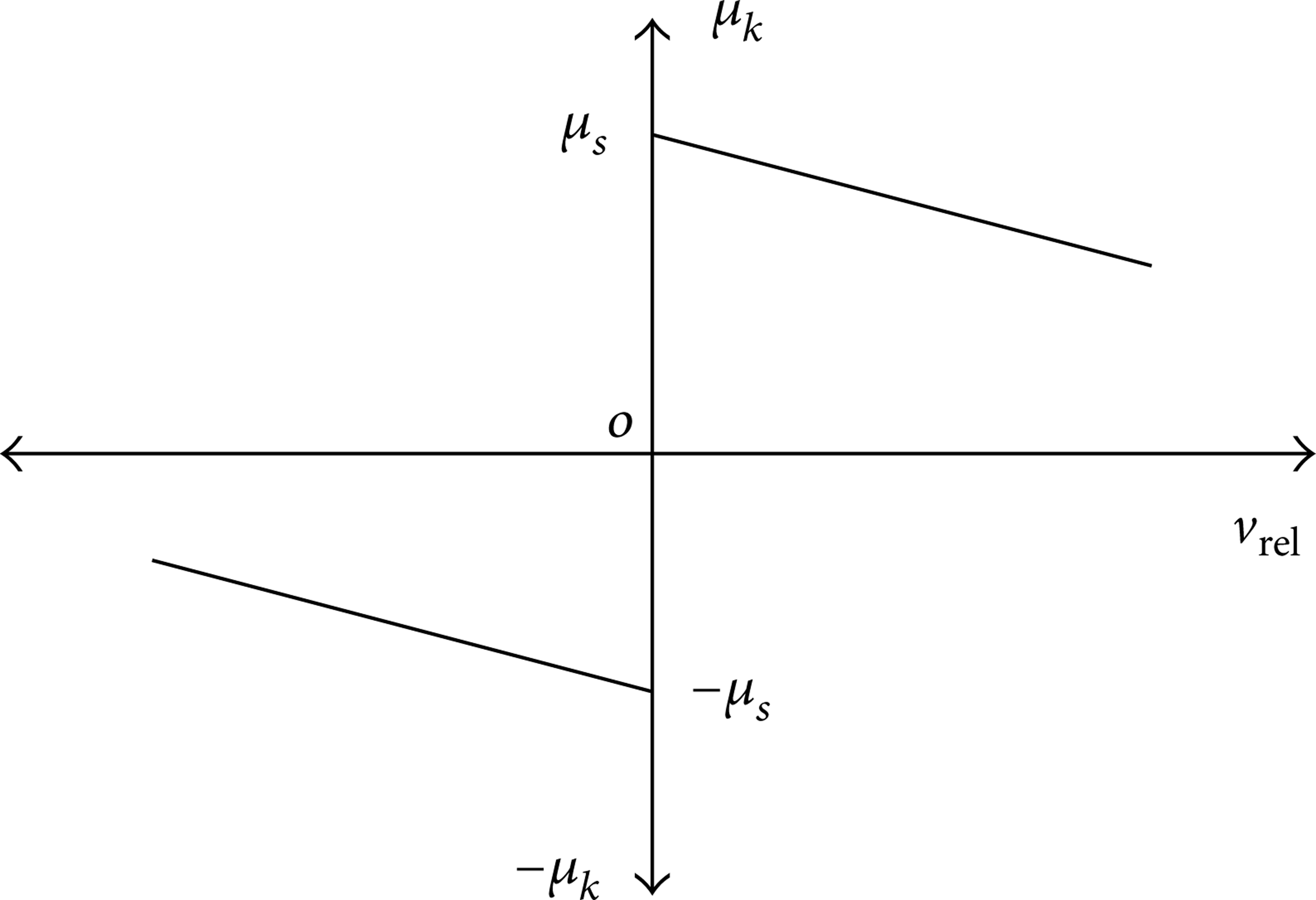
Linear dynamic friction coefficient over relative speed.
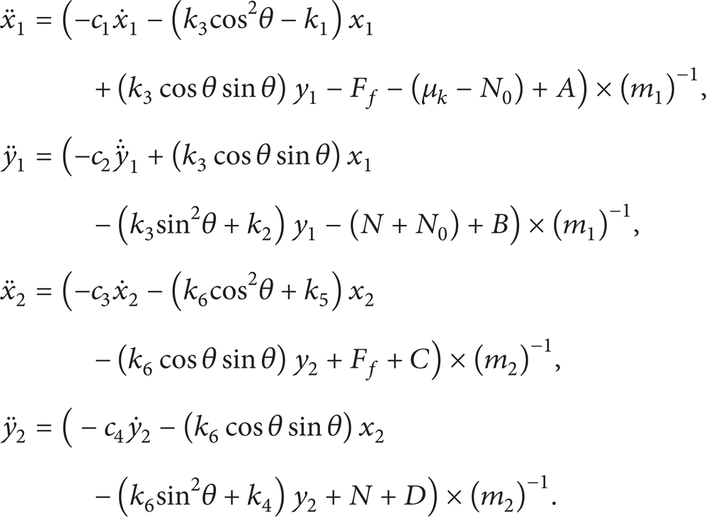
The equations of motion of the 4-DOF FIV model are given as follows:
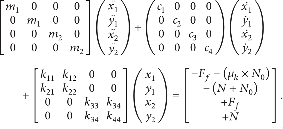
The stiffness of the spring, k, the normal force, N, and the friction force, F, are defined as follows:
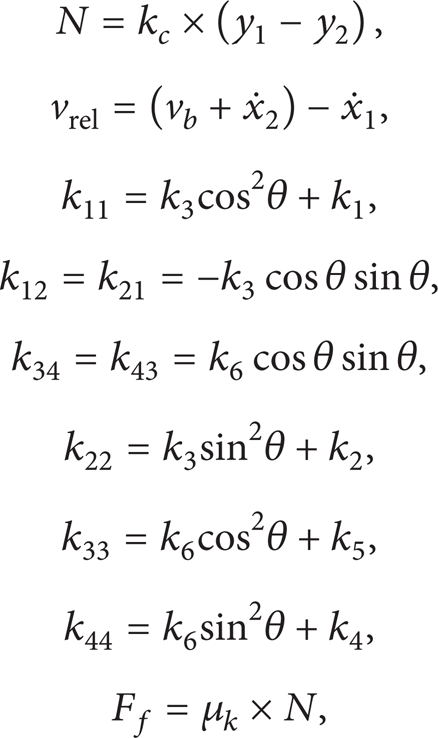
where μ k and μ s are the dynamic and static friction coefficients, respectively, v rel is the relative velocity between the slider and the block, and α is the negative slope of the linear function of friction-velocity curve. The ε in (1) is a very small positive number, and it is there to prevent the sign function from becoming zero for a situation that the relative velocity is zero. Thus if the relative velocity is zero the friction coefficient would be equal to the static friction coefficient (μ s ). It can be seen from the model that by describing the dynamic friction coefficient as mentioned in (1) the effect of negative damping is considered in the model, and with contact stiffness, K c , the stiffness matrix in (2) becomes asymmetric and hence it leads to the effect of mode coupling.
3. Control Strategy
After obtaining the mathematical model that represents the effect of negative damping and mode coupling as shown in Figure 1, it is necessary to control the vibration in all four directions x1, y1, x2, and y2 byusing actuators which can apply forces that are parallel to the given axes. Thus the equations of motion having introduced the actuators can be given as follows:
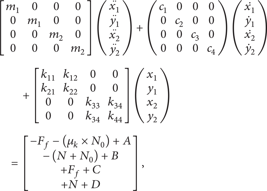
where forces A, B, C, and D are the actuator forces that are applied to the model as shown in Figure 3. Equation (4) is then derived into state space as follows:

Actuator forces applied to the model.
The control strategy that is proposed here employs an AFC-based scheme that is used in conjunction with the conventional PID controller. AFC as first proposed by Hewit and Burdess [30] is robust and effective in controlling a robot arm. Mailah and fellow researchers [31–36] demonstrated the application of the technique to include many other dynamical systems with the incorporation of artificial intelligence (AI) methods. The PID controller was first tuned with Ziegler-Nichol's method and then manipulated for fine performance. Afterwards, the AFC part is included into the system to supply the compensation of the disturbance that is inherent in the FIV system. Figure 4 shows the AFC scheme applied to a dynamic translation system of the adopted models. AFC scheme is shown to be effective in providing the actuated force and body acceleration that are precisely measured and at the same time the estimated mass suitably approximated [37, 38]. The essential AFC equation can be related to the computation of the estimated disturbance force, F d , as follows:

where F is the measured actuating force, EM is the estimated mass, and a is the measured linear acceleration. This parameter is then fed back through a suitable inverse transfer function of the actuator to be summed up with the PID control signal. The theoretical analysis with the stability of the proposed AFC method has been described in [39]. A number of methods to estimate the mass have been proposed in the previous studies such as artificial intelligence (AI) and crude approximation techniques [37, 39]. In this study, the use of crude approximation method to approximate the estimated mass is seen sufficient. The main challenge of the AFC method is to acquire suitable estimation of the mass required to compute the disturbance F d in the feedback loop. A conventional PID that is used with the AFC scheme can be typically represented by the following equation:
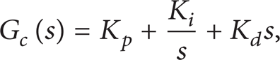
where K p , K i , and K d are the proportional, integral, and derivative gains, respectively.

Schematic diagram of AFC scheme.
4. Simulation
In order to simulate the four-DOF FIV model with the controllers, MATLAB, Simulink, and Control System Toolbox (CST) software are utilized. The actuators are assumed to be of a linear type with a suitable constant gain. They provide the necessary external energy to suppress vibration in the model. The parameters used in this study were mostly taken from the previous researchers [40–43]. However, it needs to be manipulated to suit the application in the simulation and within MATLAB capabilities. The detailed parameters are given as follows.
Mathematical model parameters:
body masses: m1 = 0.3 kg and m2 = 2 kg;
spring stiffness: k1 = 260000 N/m, k5 = 665000 N/m, k3 = 270000 N/m, k6 = 400000 N/m, k2 = 115000 N/m, k4 = 950000 N/m, and k c = 85000 N/m;
damping coefficient: c1 = 1.5 Ns/m, c2 = 1.5 Ns/m, c3 = 0.1 Ns/m, and c4 = 0.1 Ns/m;
static friction coefficient: μ s = 0.6;
normal preload: N0 = 100 N;
angle: (θ) = 60°, 45°;
initial constant velocity of the disk: V b = 20 km/h;
actuators gain: Q = 0.5 and actuators power: P = 7 Watt;
reference input = 0.00 m (i.e., no vibration).
In the simulation process, several types of operating conditions are deliberately introduced to the mathematical model to evaluate the effectiveness of the control system.
Four actuator forces for compensating the disturbance that is actually inherent in the 4-DOF model are required. The actuator forces are controlled by four individual PID controllers involving four negative feedback loops.
For better vibration prevention, AFC is integrated into the pure PID controller. The AFC Simulink diagram includes the estimated mass, EM, and the parameter, 1/Q. The input to the AFC is the mass acceleration and the output is summed with the PID controller output and then multiplied with the actuator gain which subsequently generates the actuator force. To obtain the effective results, it is required to acquire a suitable estimated mass combined with appropriate tuning of the PID controller gains. Figure 5 shows an AFC scheme used in the study to suppress vibration and it can be seen that each PID controller is added to the AFC loop. It can be noticed that four AFC loops are added to the four PID controllers.

Simulink diagram of the proposed AFC model.
In order to tune the PID controllers, Ziegler-Nichol's method is used with manipulation to suit the system performance and the results are tabulated as shown in Table 1. Also, it shows the values of the estimated mass in which they were mainly obtained by trial and error or crude approximation method. It should be mentioned that the percentage of the AFC used is 100% (switch is set to ON).
The values for the estimated mass and the PID parameters.

5. Results and Discussion
In this section the results of the four-degree-of-freedom model of friction-induced vibration, which represents both effects of negative damping and modal coupling. At first in Section 5.1 in order to approve the correctness and appropriate operation of the model some simulation tests were executed from the model when it did not have any controllers applied to it (i.e., the passive model). Then in Section 5.2 simulation tests were carried out from the 4-DOF model that was equipped with PID and AFC controllers.
5.1. Passive 4-DOF Model
By giving different values of the slope and considering the angle (θ) to be 60° [41], a number of simulations were performed using the passive FIV system, that is, without any controller attached to it. These simulation tests are executed by giving different values of the slope (α) in (1). First, a value of α = 0.01 was given and the results are shown in Figure 6. It can be seen that the response of the block (m1) and the slider (m2) in both in-plane (x1 and x2) and out-of-plane (y1 and y2) directions under the given value of the slope is converging and it is indicated that the system is under stable condition. Due to the reason that the value of the negative damping slope is considerably low, the changes of the friction coefficient with the increase of the relative velocity are superficial and thus the system is stabilizing with time. The offset that can be seen in the out-of-plane results is mainly due to the natural behavior of the system. The preload N o will initially press the block and slider down until they reach the equilibrium condition.

Vibration response of the passive FIV system with α = 0.01 and θ = 60°.
Later the slope (α) was increased to 0.03 and time domain results are shown in Figure 7. It can be seen that the block (m1) and the slider (m2) are clearly under unstable condition in the out-of-plane direction and in-plane direction. Because the slope of negative damping is higher than the previous case it causes the friction coefficient to decrease with a noticeable amount with the increase of relative velocity, and thus the response of the system goes toward instability.

Vibration response of the passive FIV system, α = 0.03 and θ = 60°.
One more simulation was performed by considering the angle θ to be 45° in order to examine its influence on the system stability. The slope was set to 0.03 and the results of this simulation are shown in Figure 8. It can be seen that when the angle θ is set to 45° both m1 and m2 are less diverging, compared to the case where the angle was set to 60°. It is also found that when the angle θ is decreased from 60° to 45°, the value of the slope that is required to make the FIV model unstable is higher.

Vibration response of the passive FIV system with α = 0.03 and θ = 45°.
5.2. Reducing the Vibrations of the 4-DOF Model with AFC
After studying behavior of the four-DOF passive FIV model, it is necessary to reduce and eliminate the vibration in it. At first the simulation is performed at the angle θ of 60° with the slope of 0.03 and results of this simulation are shown in Figure 9. It can be seen that when AFC is applied to the model, in-plane and out-of-plane vibration of the block (m1) and the slider (m2) are better reduced compared to the case that the model has only PID controllers.

Vibration response of the FIV model with α = 0.03 and θ = 60°.
By increasing the slope to 0.08 the results show that the PID controllers are not effective in reducing the vibrations and the FIV model is diverging, but by engaging the AFC loop into the PID controllers the vibrations are very effectively reduced to nearly zero as shown in Figure 10. This shows that a PID plus AFC controller is very effective in preventing vibration for a quite large range of the slope.

Vibration response of the FIV model with α = 0.08 and θ = 60°.
In order to evaluate the robustness of the system the simulation was executed with having the mass m1 reduced by 10%. The results of this simulation are shown in Figure 11, and it can be seen that AFC is still capable of reducing the vibrations to a noticeable amount.

Vibration response of the FIV model with α = 0.08 and θ = 60° and the mass m1 reduced by 10%.
Another simulation was executed with considering a nonlinear relation between the friction coefficient and relative velocity [44]; in this case the friction coefficient is considered to be in a sinusoidal format. The results of this simulation are represented in Figure 12 and they show that after AFC is engaged into the system the noise or vibration reduces to a suitable manner. The out-of-plane vibrations showed the same behavior.

Vibration response of the FIV model with α = 0.08 and θ = 60°, with a nonlinear sinusoidal friction coefficient.
6. Conclusion
A four-degree-of-freedom linear model of a friction-induced vibration system has been developed, in which both mechanisms of negative damping and mode coupling which are two of the most important mechanisms that cause friction-induced vibration are represented. An active force control-based method has been developed and implemented to significantly reduce the vibration caused due to the effects of negative damping and mode coupling. The AFC component is readily incorporated into a PID controller and the resulting four-DOF scheme has been shown to be very effective in suppressing the vibration in the 4-DOF FIV model for a number of different operating conditions. It was observed that, in some cases, a pure PID controller alone is able to reduce the vibration but more often than not it is much less effective compared to the PID plus AFC scheme.
With the increase in the slope of the linear friction coefficient in negative damping, a pure PID controller was unable to stabilize the system and the vibration was shown to gradually increase in amplitude with time. However, when the AFC mode is activated, the vibration was very much reduced, thereby rendering the system very effective. It is worth to see whether the AFC mode is capable of suppressing vibration if nonlinear aspects of the surface contact and of mu-velocity slope are considered. This is the authors’ recent work. Due to the equipment and the required hardware that are used for the AFC system, the cost of this method at the moment is expected to be expensive and thus it can be used as a luxury option or in sensitive cases.
Conflict of Interests
The authors declare that there is no conflict of interests regarding the publication of this paper.