
Abstract
In order to reduce the environmental contact force and make the operation task completed successfully, the robot is frequently required with force perception and active compliance control. Based on the six-axis wrist force sensor measuring, a robot model of surface tracking motion is proposed, and its force control algorithm and experiment are studied. The measurement principle of the six-axis wrist force sensor and the inadequacy of the sensor measuring the six-dimensional force online are introduced firstly. The surface tracking motion model and its coordinate system are established. On this basis, the relationship between the pose adjustment of surface tracking motion and the measuring results of the six-axis wrist force sensor is deduced. At last, the experimental study of the surface tracking robot system that applied the force control algorithm is conducted. The experiment shows that the robot can adjust the current position and orientation in real time according to the six-axis wrist force sensor measuring, which demonstrates the feasibility of the surface tracking motion model and the correctness of the force control algorithm.
1. Introduction
Sensor-based intelligence is the highest expression of automation, the important feature of robot intelligence is perception, adaptation, and action to external environment and object. The active force control of robot is the essential tool to achieve automation and intelligence, the essence of that is some extent imitation to the function of body force sensing [1, 2]. When robots execute some operation task, the terminal actuator and rigidity environment will generate a big environment constraining force due to tiny displacement. Robot often needs to possess the force sensing perception and the capability of active supple control for reducing environment contact force and then for operation task could be able to finish.
Force sensor is an essential tool of intelligent robot active supple control research, and the performance of sensor affects force control performance directly [3]. High precision (resolution, sensitivity, linearity, etc.), great reliability, and the strong capacity of anti-interference are the targets of intelligent robot force sensor research. Scholars have developed different structure form six-axis force sensors and apply them to robot wrist, ankle, six-axis controller, heavy force measure, and so forth field [4, 5]. Estevez et al. [6] presented the design, fabrication, and characterization of a piezoresistive 6 degrees of freedom force and torque sensor to be used in micromanipulation. Dwarakanath et al. [7, 8] reported the sensor with the idea of “joint less” structure and beam and designed a Stewart platform-based force sensor by considering maximization signal-to-noise ratio and satisfying the dual objective of isotropy and sensitivity. Kim et al. [3, 9] developed some kinds of six-axis force/moment sensor for a humanoid robot's intelligent foot. Palli and Pirozzi [10] presented the design and experimental evaluation of a miniaturized optical force sensor for tendon-driven mechatronic systems. Cappelleri et al. [11] presented a two-dimensional, vision-based force sensor, capable of sensing micro-Newton level forces for use in microrobotic applications and discussed the modeling, design, microfabrication, calibration, and experimental validation of the force sensor. Kondoa et al. [12] developed a new measurement system of reaction force from snow surface which consists of four compact size 3-axis force sensors to measure the force of 6-axis components. Buttafuoco et al. [13] described a force sensor for 2 degrees of freedom haptic applications and apply it to a force feedback teleoperated device to allow the medical doctor to essentially feel the lung without making physical contact.
The curved surface contour tracking based on six-axis wrist force sensor is the very familiar typical compliant motion. Currently, most of them adopt laser sensor to complete measuring and tracking to the curved surface [14–16]. Ding et al. [17] have researched one kind of contacting curved surface measure robot system and solved the question of curved surface pattern measure. Thus, applying wrist force sensor to do the contacting curved surface contour tracking is judging the contact status of robot and environment in real time which according to the detected force by force sensor, so that the robot can track the unknown surface. This can avoid the interference of external environment, reduce the unstable factors, and enhance the tracking precision and the responding speed.
This paper proposed a kind of robot surface tracking motion model based on the wrist six-axis force sensor feedback control. The surface tracking motion measuring of force control and experiment are performed. The model of surface tracking motion can apply to clean surface glass, weld surface spare parts, explore wound, measure complex surface, and so forth in industrial production.
2. Measuring Principle and Limitation of Six-Axis Wrist Force Sensor
2.1. Screw Theory Basis
Screw theory [6] is presented to analyze the measure theory of robot end wrist six-axis force sensor. Mathematical model of robot end wrist six-axis force sensor measure theory based on screw theory is created firstly, which is the basis to propose and verify the limitation of six-axis force sensor in advance measure. It is has great significance to the improvement of curved surface tracking model based on six-axis force sensor.
Space forces system which acts on a rigid body can finally be synthesized as a force screw with determined position. Expressed in the form of Plücker coordinates, the summation of a force vector and couple vector with lines of the force vector can be expressed as f i (S i ;S i 0 − h i S i ) and f i (0;h i S i ).
Force screw can be expressed as scalar product of a force f i and an unit of screw $ i , f i $ i = f i S i + ϵf i S i 0. It can be written as follow:

where ϵ is the dual sign and ϵ2 = ϵ3 = ⋯ = 0. First item of (1) is force of direction with S i . The second item is the summation that the moment f i S0i of force to origin and the couple vector of direction with S i , which is also the moments of the force system to origin. Equation (1) can also be abbreviated as f i $ i = f i + ϵC0. With f i and C i 0, the force screw can be shown as

The pitch of force couple C i , which with the same axis of the screw shaft, is simplified as

The pitch of force screw is that the module of force couples with the same axis of the screw shaft divided by force module, which is the invariant of origin.
When the force couples C i of the force screw which along the direction of S i equals 0, then the pitch is zero too and the only force has an effect on the rigid body. When the force f i of the screw force is 0, the pitch is infinite and the rigid body is only affected by force couple.
2.2. Measuring Principle of Six-Axis Wrist Force Sensor
Six-axis wrist force sensor is an important sensor of intelligent robot which can simultaneously measure the full force/torque information in three-dimensional space (Cartesian coordinates), that is, three force components and three moment components, to make robot to engage in precision assembly, automatic grinding, contour tracking, hands, and coordination operations like precision assembly, automatic grinding, contour tracking, and hand coordination. It has been widely used in the aerospace, machining, and assembly, automotive, and other fields.
Measurement system of six-axis wrist force sensor usually consists of six-axis wrist force sensor, data acquisition devices, computers, and so on. As shown in Figure 1, when an external force is applied to the sensor, each sensitive parts’ output voltage of sensor will change, and then output voltage is transferred to the computer by the data acquisition. In Figure 1, V1 ∼ V
n
represent each sensitive parts’ output voltage of six-axis wrist force sensor and matrix [

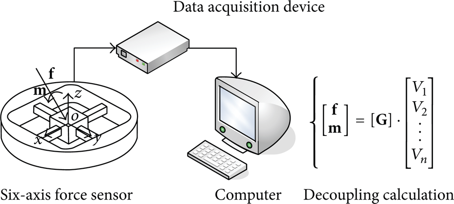
Measurement system of six-axis wrist force sensor.
2.3. Limitation of Six-Axis Wrist Force Sensor
Although the six-dimensional space force can be detected by six-axis wrist force sensor, the result detected is only six-dimensional form expressed of external force in the sensor measurement coordinates. Well known, there are three elements of the force that size, direction, and action points. Is it possible to get the three elements of six-dimensional space force from the six-dimensional wrist force sensor's measuring results, that is, the size, direction, action points of force, and the size, veer, action surface orientation of the force couple.
Next, the information which can be measured by six-axis wrist force sensor will be labor from the different form of applied six-axis external force. Figure 2 shows generalized six-axis external force in sensor measurement coordinate system o
s
-x
s
y
s
z
s
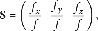
. The scalars f, m express size of force vector and couple vector, unite vectors
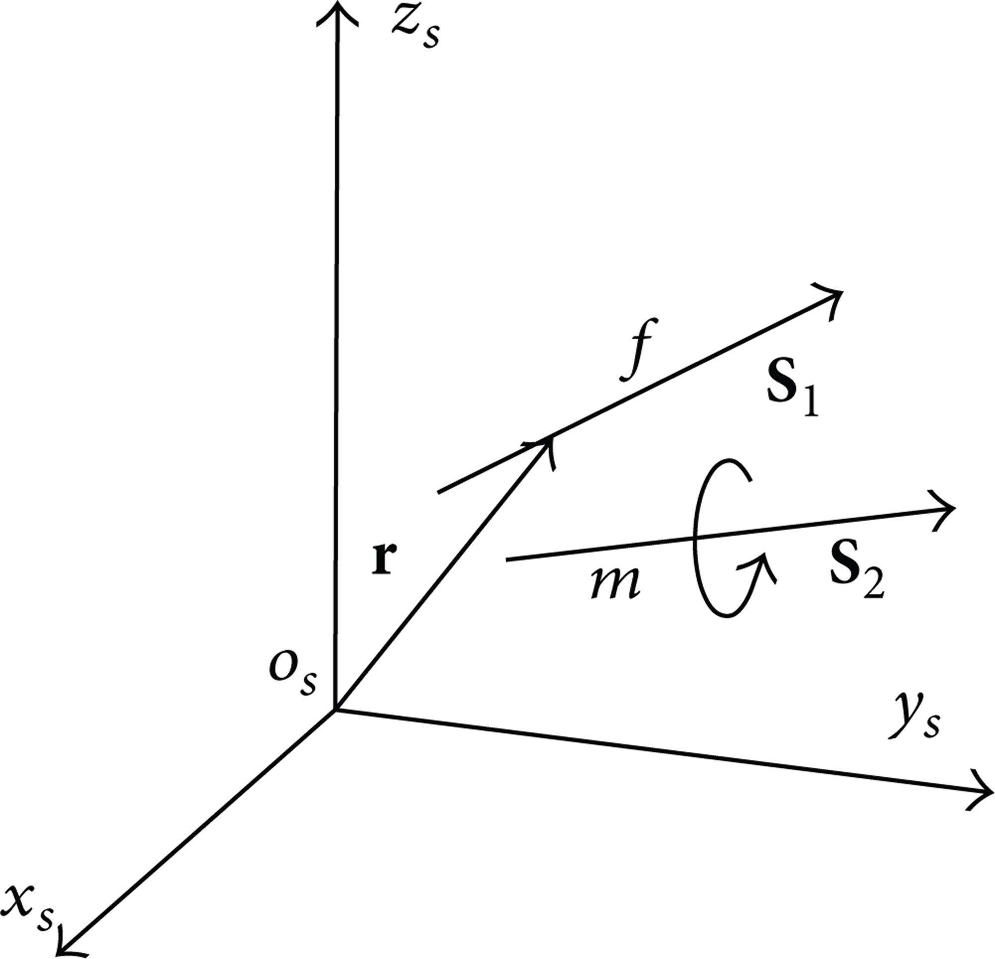
General six-axis force expressed on the measurement coordinate system.
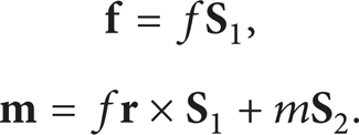
According to (1), in sensor coordinate system, force vector in the form of screw can be expressed as

where
Equation (5) in the form of Plücker coordinates can be expressed as

Similarly, the couple vector can be expressed as

where m
By (6) and (7) force vector and couple vector are combined into one volume by screw algebra, which can be written as

Equation (8) represents the generalized six-axis force screw as the scalar product of force
Combined (4) and (8), a relationship between the expression of generalized six-axis force screw and the measurement results of sensor obtained
Measurement results [
Measurement results of the six-axis force sensor with different forms of external forces.
As can be seen from the table, no matter what form of the six-axis wrist force (force vector, couple vector, and force screw) is, the action point cannot be obtained by six-axis wrist force sensor. When the form of external force is force vector, the size, orientation, and action line can be detected. Since the couple vector is free vector, the effect of their position can be ignored. When the external force is couple vector, the size, veer, and action surface orientation of it can be detected. When it is force screw, the size and orientation can only be detected, while the action line and the magnitude of the force vector and the couple vector in measurement results cannot be decided. Therefore, to obtain accurate form of six-axis force acting on the sensor, the actual operation of the contact surface equation must be combined to solve.
3. Model of Surface Tracking Motion
The curved surface tracking motion is one of common motion models in robot force control operation in some occasions, such as cleaning glass, welding, curved surface polishing, curved surface measuring, and so forth, which request robot to track or detect unknown curved surface and achieve to move along the unknown curved surface with some kind of posture. The curved surface tracking motion proposed in the paper is achievement through force feedback information of the six-axis wrist force sensor.
The model of robot curved surface tracking motion based on the six-axis wrist force sensor force control is shown in Figure 3. One end of six-axis wrist force sensor mounted on the robot arm, another end connected a ball finger. The finger is equipped with spring, which ensures that the finger only can retract along the axial of the finger. The planned curved surface tracking motion is that the process of robot finger motion keeps contact with the curved surface and ensures the finger keeps vertical always with the tangent plane of curved surface contact point. The ball finger keeps a certain pressure with the curved surface. The projection on level of the finger and curved contact point is a given trajectory. The curved surface tracking motion model is a simplified model in actual production such as cleaning glass, welding curved surface, and so forth operations, which express contact and stress form of these operations from some extent. The theory analysis and experiment research to the model have important practical value on the application of six-axis wrist force sensor and achievement of force control.

Diagram of surface tracking motion model.
4. Force Control Algorithm of Surface Tracking Motion
4.1. Establishment of the Coordinate System
In order to complete the planned trajectory of surface tracking motion, when the robot trajectory planning is completed, it must be based on the six-axis wrist force sensor measuring of the contact force and in accordance with a certain force control algorithm to adjust the current position and orientation in real time. The coordinate system of curved tracking motion model is created as shown in Figure 4. Trajectory of curved tracking motion is the contact point of the surface and the robot finger movement from point o1 to point o2. The coordinate system o-xyz is built with the coordinate origin on sphere center of robot finger. The coordinate system o s -x s y s z s indicates the sensor measuring coordinate system. Those two coordinate axes are on the same direction, and the z-axis is collinear.

Coordinate system of surface tracking motion model.
Because the resultant of contact force is line vector in process of surface tracking motion, assuming the contact surface friction ignored, the force
4.2. Force Control Algorithm
Robot pose adjustment coordinate system is built as shown in Figure 5. Coordinate system o-xyz is the initial robot coordinate system, denoted by {A}, and o-x′′y′′z′′ is the robot coordinate system after pose adjustment denoted by {B}. Describe the transformation with X-Y-Z Euler angle as that coordinate system {A} rotate angle α about the x-axis first, then rotate angle β about the y′-axis, and finally rotate angle γ = 0 about the z′′-axis and coordinate system {B} is obtained. Whereby a rotational transformation matrix can be obtained as

where sα = sinα and cα = cos α.

Coordinate system of pose adjustment.
Let γ = 0 in (10); then

Assuming the six-axis force measured in the sensor measuring coordinate system o
s
-x
s
y
s
z
s
is

where
The relationship of the position and attitude between the two coordinate systems can be obtained as

where d is distance between two coordinate origins o and o s .
The unit direction vector of force vector
where
Assuming that the orientation of three axes of the coordinate system {B} relative to the coordinate system {A} was

Since the posture after adjustment is that the force vector

Combining (11), (15), and (16), we have

Consequently, solving (17) we can obtain

Equation (18) obtains the force control algorithm of the end effector posture adjustment when robot finished surface tracking motion. Then the robot finger axis position adjustment amount can be deduced as the following derivation. Assuming a constant force between the finger and the surfaces needs to be maintained in the process of curved surface tracking motion. The following expression can be obtained by the measured z-orientation force

where q z is the position adjustment amount of robot finger along its axis. k is the stiffness coefficient of spring on robot finger.
The relationship between adjustment amount of robot posture and position needed and detection value of six-axis wrist force sensor is obtained so far, which can make the sphere center of finger moves as the reference point in the process of curved surface tracking motion. It laid the theoretical foundation for the force control experiment of robot curved surface tracking motion.
5. Experimental Research
5.1. Experimental System
Surface tracking motion experiment system is shown in Figure 6, which consists of six-axis wrist force sensor, 6-Dof robot, IPC, data acquisition instrument, and so forth. The robot and wrist sensor of the experiment system are independently developed. The six-axis wrist force sensor [18] has several characteristics such as less coupling, high precision, good measurement stability, and so forth. And the measurement error of wrist force sensor is less than 1% F.S. which can ensure the accuracy requirement to force control. The 6-Dof robot to complete the curved tracking motion is the 6-PUS parallel robot [19]. This kind of robot has characteristics of symmetrical structure, high precision, flexible drive, and so forth. It can be used to research on the vision measurement, contour tracing and force control, and so forth. The control system software is compiled by VC++ language.

Surface tracking motion experiment system.
5.2. Experimental Results
The flow chart of robot surface tracking motion control system which based on feedback of six-axis wrist force sensor is as shown in Figure 7. After program initialization, task trajectory planning is proceeded based on the completion of the motion firstly, and then the feedback algorithm is put into the robot control system based on the derived results in Section 4. Every time when the program executes a cycle, it may determine that whether there are forces on the wrist force sensor and turn the forces of sensor detection into the posture and position alteration of robot control system. Finally the robot finger keeps vertical to the surface and move along the planning trajectory.

Control flow chart of the surface tracking motion.
The planning experiment trajectory is that the robot finger moves along y-axis direction of fixed-coordinate system O-XYZ as shown in Figure 8. At this time, the displacement of robot finger along z-axis and the rotation angle α around x-axis of the moving coordinate system o-xyz will change based on force feedback of the wrist sensor measuring in real time, so that the robot finger may keep vertical with surface throughout.

Planning trajectory of surface tracking motion.
The experimental results of surface tracking motion are shown in Figure 9. In the whole experimental process, the demand of system precision and ability of real-time are ensured by the six-axis wrist force sensor, and the parallel robot is able to keep the finger vertical with the contact surface according to the deduced force control algorithm. Thereby force sensing and force control to an unknown environment of the robot are achieved finally.

Experimental results of the surface tracking motion.
Figure 10 shows the variation curve of robot posture angle α versus the horizontal direction displacement y of the finger center. Figure 11 is the variation curve of z-direction displacement versus y-direction displacement of the finger center. The experimental results show that the experimental values are agree well with theoretical values. The maximum deviation of the posture angle α- and z-direction displacement between the experimental results and the theoretical ones is 1.5° and 0.8 mm, respectively. The experiment indicates that the robot can detect the external force of the contact surface according to the six-axis wrist force sensor and feedback it to control algorithm. According to the control algorithm, position and orientation of the robot can be changed correctly, which demonstrates the correctness of the force control algorithm analysis. Because of the existences of the system error and interface friction, the position and orientation of robot after adjustment are slightly lagging behind the theoretical values. Through the methods of surface lubrication and reducing the system error, it can enhance the control precision of robot system.

Curve of the pose angle α versus the horizontal displacement of the finger.

Curve of the displacement along z-axis versus the horizontal displacement of the finger.
6. Conclusions
By the analysis above it is concluded that no matter what form of the six-axis wrist force (force vector, couple vector, and force screw) is, the action point cannot be obtained by six-axis wrist force sensor. Therefore, to obtain accurate form of six-axis force acting on the sensor and achieve further precise control of robot gripper ends, the actual operation of the contact surface equation must be combined to solve.
The force control algorithm of the surface tracking motion based on six-axis wrist force sensor measuring information in unknown environment is developed. The surface tracking motion model is established firstly. Then according to the model, the force control algorithm of surface tracking motion based on six-axis wrist force sensor measuring is inferred. Finally, the surface tracking motion robot system is developed, and the experimental research is performed. By the variation curve of robot position and orientation, the experimental values are agree well with theoretical values which demonstrates the correctness of the force control algorithm analysis. The experimental results show that based on the force feedback by six-axis wrist force sensor, robot can change the current pose in real time and complete the planning surface tracking motion. The contents of research have practical value to six-axis wrist force sensor application and the robot force control research based on six-axis wrist force sensor.
Conflict of Interests
The authors declare that there is no conflict of interests regarding the publication of this paper.
Footnotes
Acknowledgments
This work is financially supported by Natural Science Foundation of Hebei Province under Grant no. E2012203130 and the Scientific Research Foundation of Hebei Provincial Education under Grant no. QN20131105.