
Abstract
The aim of this work was to present iterative learning tracking control of a hybrid-driven based three-cable parallel manipulator (HDCPM). The HDCPM has the advantages of both cable parallel manipulator and hybrid-driven planar five-bar mechanism. Design of the HDCPM is described and dynamic model is developed on the basis of Lagrange method. Consider the HDCPM system with nonlinear, time-varying characteristics and repetitive unknown disturbances; an adaptive iterative learning control strategy, which can control gains change with the iterations, is designed. By means of Lyapunov function, the stability of the controller is proved. Finally, simulation results indicate that a perfect trajectory tracking of the HDCPM is achieved by the adaptive iterative learning controller, which also illustrate the correctness of the dynamic modeling and effectiveness of the proposed control strategy.
1. Introduction
Cable parallel manipulators (CPMs) are parallel manipulators in which cables are used instead of rigid links, which are generally known for simple and light-weight structure, large reachable workspace, high acceleration capability, and easy reconfigurability [1–5]. Based on the preceding characteristics, the CPMs play an important role in many engineering fields, such as load lifting and positioning, coordinate measurement, aircraft testing, super antenna, and haptic devices [6, 7]. The CPMs are incompletely restrained if they rely on gravity to determine the pose (position and orientation) of the end-effector, while they are completely restrained if the pose of the end-effector is completely determined by the lengths of the cables. As far as previous research on the CPMs is concerned, Baser and Konukseven developed an analytical method for predicting the transmission error [8]. Workspace and stiffness analysis of cable-driven manipulators considering cable mass has been investigated by Arsenault [9]. Different aspects like time optimal trajectory tracking [10], workspace [11], and bounded cable tensions [12] were also investigated extensively. Notash and Kamalzadeh [13] investigated the dynamics of wire-actuated parallel manipulators with a constraining linkage by Lagrangian method. Flatness-based trajectory tracking control for a kinematically undetermined three-cable suspension manipulator has been investigated by Heyden and Woernle [14]. Oh and Agrawal [15] have considered a problem of positive tension controllers for cable suspended robots with redundant cables.
In recent years, the CPMs are finding increased use in a wide variety of modern engineering applications. Therefore, they are required not only for operations with high accuracy and high payload but also for output with greater flexibility, which can change the law of output motion quickly and conveniently [16]. Nevertheless, the existing research on the drive system of the CPMs usually uses the low power controllable motor. The low power controllable motor cannot directly drive the high-loading CPMs due to the restrictions of power and torque. Hence, it is necessary to carry out for a new-type drive system for the CPMs. The hybrid-driven planar five-bar mechanism (HDPM) is a kind of machine whose drive system consists of a constant velocity (CV) motor and a servomotor [17, 18]. The CV motor provides main power and motion required; however, it lacks flexibility. On the other hand, the servomotor acts as a motion regulation device which suffers from the limited power capacity and high cost. The HDPM can, therefore, take the advantage of the complementary characteristics of both motors to generate a programmable range of highly nonlinear output motions with high power capacities at low costs [19]. In this investigation, the design of a hybrid-driven based three-cable parallel manipulator (HDCPM) is described. The HDCPM can take the advantages of the characteristics of both mechanisms to generate a high-performance output motion [20, 21].
It is well known that dynamic performance has a great impact on the operation of the manipulator, and this is on the basis of its dynamic control. As demonstrated in [22], servomechanism dynamics constitute an important component of the complete robot dynamics. Therefore, for the HDCPM, the dynamics should not only consider the CPM but also include the HDPM, which can be seen as a type of servomechanism. There are many different approaches for derivation of the dynamic equation of the parallel mechanism. The Lagrange method is applied to investigate the dynamics of the HDCPM in this paper. The HDCPM is a nonlinear multivariable dynamic system and suffers from structured and unstructured uncertainties, such as payload variation and external disturbances. In addition, because of the changes in cable length and joint force, the CV motor of the HDPM will bring in the velocity fluctuation, which cannot be attenuated by the CV motor itself, due to the lack of a control mechanism in the CV motor, yet be propagated to the servomotor, and further to the end-effector of the HDCPM. Therefore, it is of interest to investigate the control of the HDCPM, and the control problem of the multivariable systems becomes more challenging [23, 24]. The adaptive control can cope with parameter uncertainties including the link length, mass, and inertia [25]. However, it requires extensive computation and will not guarantee the estimated parameters of the manipulators to converge to their true values, and the tracking errors would repeatedly be brought into the system when the manipulators repeat their task [26].
In order to achieve a high-precision performance, the HDCPM control system must effectively and accurately manipulate the motion trajectory of the end-effector. Since the HDCPM is generally used in repetitive task, one should take advantage of the fact that the reference trajectory is repeated over a given operation time. Iterative learning control (ILC) is a well-established technique that presents itself as the most suitable method to improve on repetitive tasks without excessive requirements on sensor-feedback quality or control-loop bandwidth. Specifically, ILC is a simple and effective technique of tracking control aiming at improving system tracking performance from trial to trial in a repetitive mode [27]. The basic principle of ILC is to use information collected from previous executions of the same task repetitively to form the control action for the current operation so as to improve tracking performance from iteration to iteration [28]. For this kind of control scheme, it has a lot of applications such as robot arm manipulators, assembly line tasks, chemical batch process, reliability testing rigs, continuous casting process [29]. The aim of the work presented in this paper is to develop dynamic model of the HDCPM, and in view of the nonlinear, time-varying characteristics and repetitive unknown disturbances of the HDCPM system, a control strategy incorporates traditional feedback PD control with iterative learning control which is designed for the high-precision trajectory tracking of the HDCPM control system.
The paper is organized as follows. Section 2 describes the design model of the HDCPM. Following, dynamic modelling of the HDCPM is performed based on Lagrange method in Section 3. An adaptive ILC method is designed for the HDCPM in Section 4. In Section 5, illustrative simulation studies highlight its performances. Finally, some concluding remarks are summarized in Section 6.
2. System Description
The incompletely restrained HDCPM with three translational motions suspends an end-effector by three cables and restrains all motion degrees of freedom for the object using the cables and gravitational force when the end-effector moves within the workspace (see Figure 1). For each cable, one end is connected to the end-effector, and the other one rolls through a pulley fixed on the top of the relative cable tower rack and then is fed into the HDPM [21].

Three-dimensional model of the HDCPM.
A simple schematic sketch of the HDCPM structure model with the associated coordinate systems is depicted in Figure 2. At the bottom of one cable tower rack, a global coordinate system O(XYZ) is established. The end-effector has location coordinates G(X, Y, Z). The distance between each cable tower rack top A i (X i , Y i , Z i ) and the end-effector is L i (i = 1, 2, 3). The three cable tower racks have the same height and are arrayed in a triangle on the ground, when deformation is ignored. In order to simplify the model, the cables are treated as a massless body with no deformation. At the bottom of the HDPM, a local coordinate system (x′o′z′) is established.

Schematic sketch of the HDCPM.
3. Kinematics and Dynamics
Figure 3 displays the structure diagram of the ith group of the HDPM and cable. Link AE is fixed on the ground. Link AB driven by a CV motor and link DE driven by a servomotor are two driving links. Link BC and link CD are driven by the two driving links, so that the joint C is the output. This paper assumes that the links have the same density, and the centroid is in the center of links. The lengths of the links are l1, l2, l3, l4, and l5, the angle between links and x′-axis are θi1, θi2, θi3, θi4, and 0°, the mass of links are m1, m2, m3, and m4, the rotational inertia of links is J1, J2, J3, and J4, and the mass of the end-effector is m, respectively.
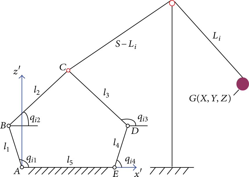
Structure diagram of the ith group of the HDPM and cable.
3.1. Kinematics
Link AB driven by a CV motor and link ED driven by a servomotor are the two driving links, as shown in Figure 3, and the joint C is the output. There are two independent constraints in the HDPM, which can be used to derive the kinematic equation of the HDPM:

In (1), θi1 and θi4 are known. Consequently, θi2 and θi3 can be calculated by θi1 and θi4 specificity as follows:

where

Let (x C ′, z C ′) be the coordinates of joint C in the local coordinate system, and it can be expressed as

According to the geometric relationship of the HDCPM, L i can be derived as

where p represents the distance
Hence, the end-effector coordinates (X, Y, Z) of the HDCPM can be obtained by

3.2. Dynamics
Mathematical dynamic models of the HDCPM system are essential for good control design and analysis. In order to obtain a sufficient representation of the dynamical HDCPM behavior, a rigorous model of the HDCPM is derived using the method of Lagrange method.
Angular displacements θi1 and θi4 of the two driving links are selected to be as generalized coordinates, and the angular velocity of all links can be expressed as

The centroid velocity of each link in x′ and z′ directions can be expressed as follows:

From (7) and (8), one can derive the kinetic energy of the ith group of the HDPM:

where
Then, the sum of kinetic energy of three groups of the HDPM is the following:

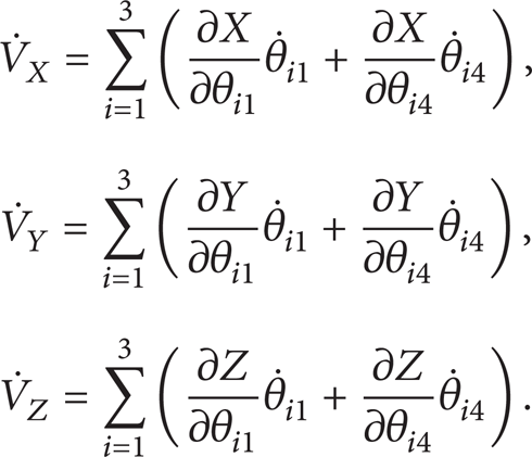
The velocity of the end-effector of the HDCPM in X, Y, and Z directions can be written as
Thus, the following kinetic energy of the end-effector of the HDCPM will be obtained:

where

In view of (11) and (13), the total kinetic energy of the HDCPM system can be generated as

The potential energy of the HDCPM system can be expressed as

Using Lagrange's equation,

where
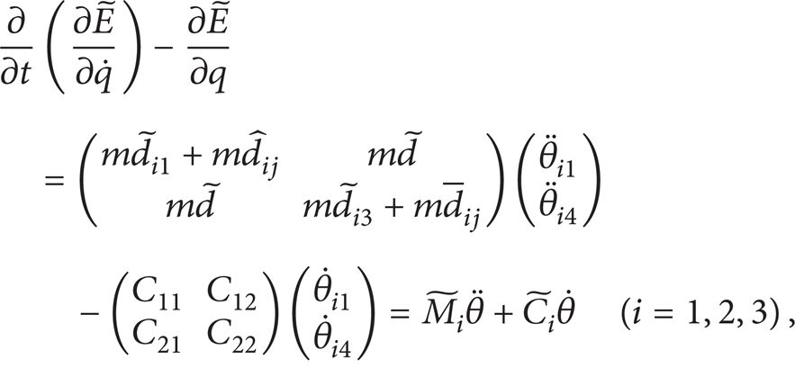
Substituting (9)–(16) into (17) yields

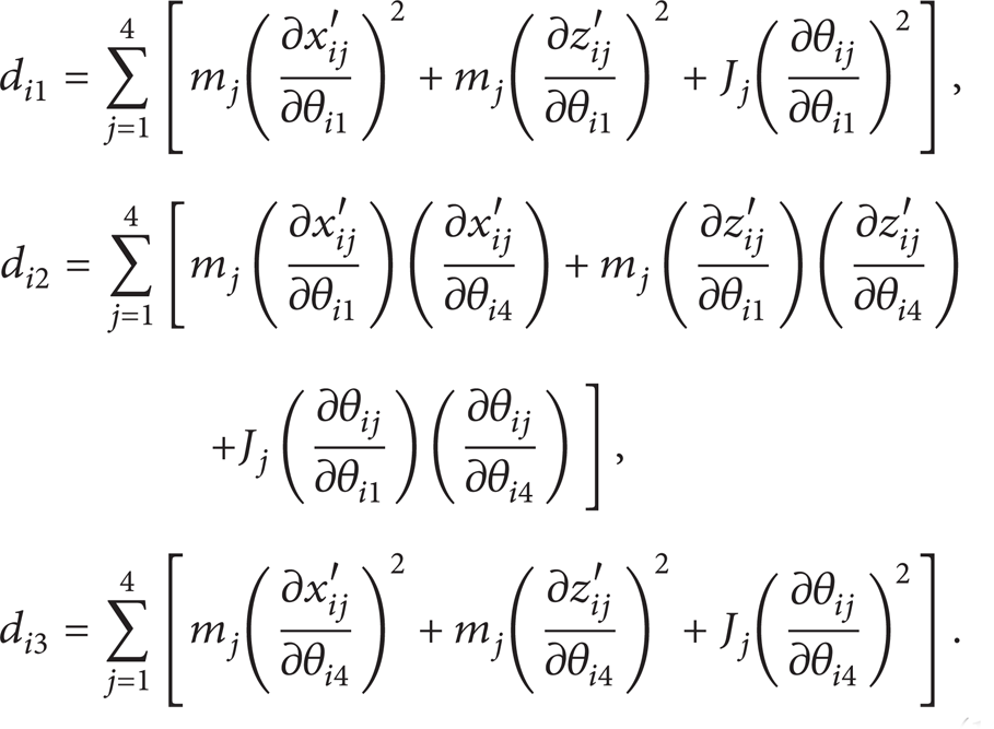
Each item in (18) can be described as follows:

where

In the case of the HDCPM model subject to random disturbances, the generalized forces can be written as

where
Based on (18)–(22), the nominal model of the HDCPM system can be described as

where
4. Adaptive ILC Design
An adaptive ILC method is designed for control of the HDCPM system [28]. Consider the dynamic model (23) of the HDCPM system in iteration domain; it can be described as

where t ∈ [0, T] is the time and n ∈ N denotes the operation or iteration number.
It is common knowledge that robot manipulators have the following properties.
(B1) The desired input angular q d (t) is of the third-order continuity for t ∈ [0, T].
(B2) For each iteration, the same initial conditions are satisfied q
d
(0) − q
n
(0) = 0,
In the single operation mode, the PD control feedback with the gain is used, where information from the present operation is utilized. In the iterative operational mode, a simple iterative learning control is applied as feedforward where information from previous operations is used. Together with these two operational modes, all information from the current and previous operations is utilized. For system (24), consider the nth iterative operation with requirements B1 and B2 in the light of the following control law:

where K
p
n
= β(n)K
p
0, K
d
n
= β(n)K
d
0, β(n + 1) > β(n) > 1 (n = 1, 2,…, N), K
p
0 represents the initial proportional control gain, K
d
0 represents the initial derivative control gain, and K
p
0 and K
d
0 are the diagonal matrix. K
p
n
and K
d
n
are the control gains of the nth iteration. t−1(t) = 0, e
n
(t) = q
d
(t) − q
n
(t),
The gain computational method is used to adjust the PD gains from iteration to iteration. Such a control method acts not only in the time domain but also in the iterative domain, which is the main difference with the traditional control method. The block diagram of adaptive ILC system for the HDCPM is shown in Figure 4.

Block diagram of adaptive iterative learning control system for the HDCPM.
Equation (24) can be linearized by Taylor formula along the desired value

where

For the n + 1 th iteration, (26) can be rewritten as follows:
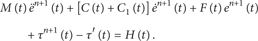
To simplify the analysis, let K p 0 = ΛK d 0 for the initial iteration, and define the parameter
The following theorem can be proved.
Then, for t ∈ [0, T], the resulting HDCPM system guarantees q
n
(t) → q
d
(t) and
Proof. To analyze the stability of the HDCPM system, a Lyapunov function candidate V is designed as [26]
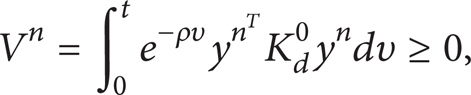
where K d 0 > 0 and ρ is a positive constant.
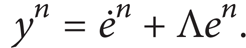
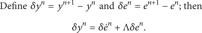
Define δy n = yn + 1 − y n and δe n = en + 1 − e n ; then
In view of (25)–(28) and (32), one can get

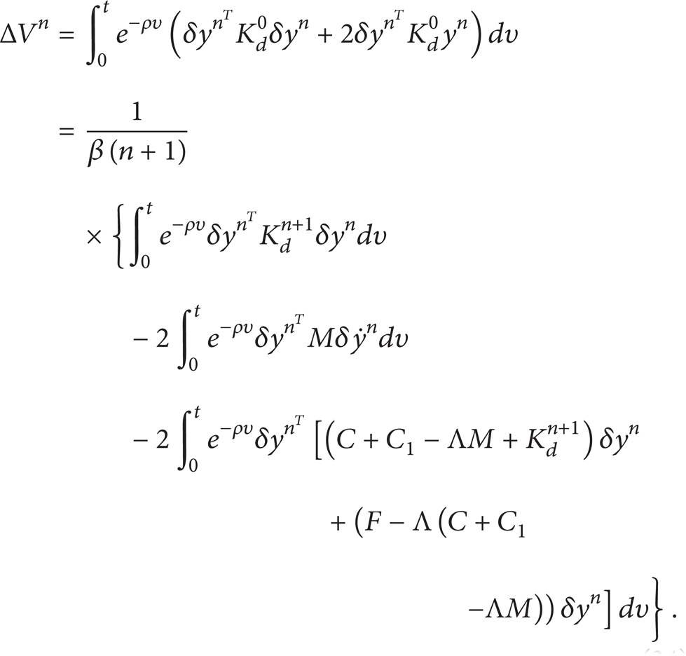
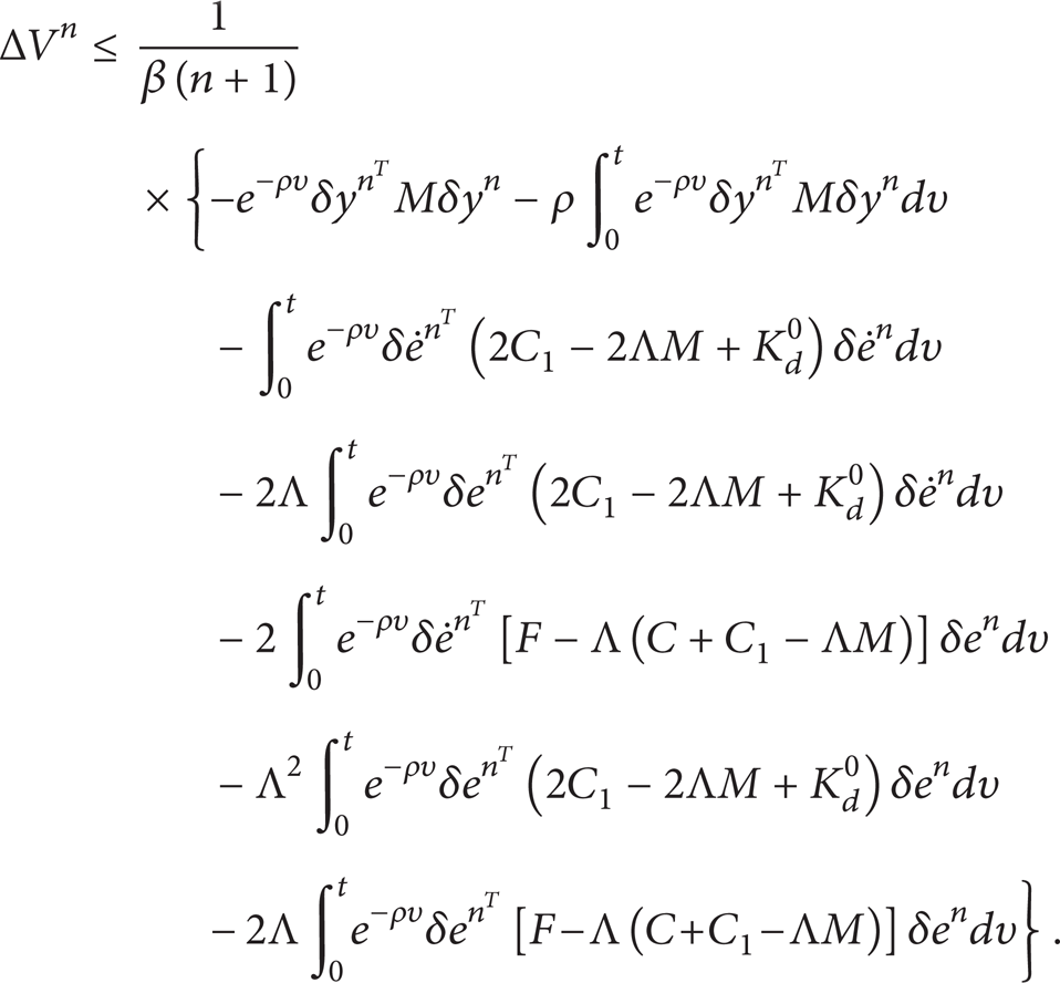
Define ΔV n = Vn + 1 − V n ; combining (31), (32), and (33), the following equation can be derived:
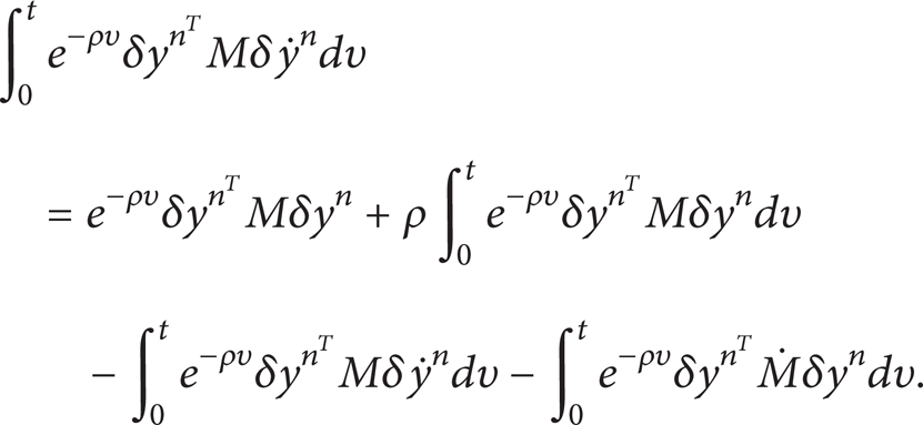
Applying the partial integration, and considering δy n (0) = 0, we have
Consider the following equation:
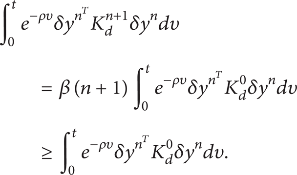
Combining (32), (34), and (35), and considering (36), one can obtain the following equation:
For the sake of simplicity, we further have

where

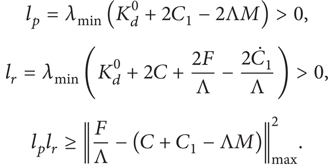
Let Q = F/Λ − (C + C1 − ΛM); then from (30), we can get

Using the Cauchy-Schwartz inequality equation [30],
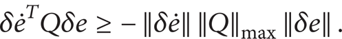
According to (30) and (41), (40) can be rewritten as
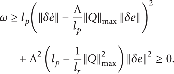
From dynamic equation, M(q) is the symmetric positive definite inertia matrix, and from (30) and (38), it can be ensured that ΔV
n
≤ 0. Therefore, Vn + 1 − V
n
≤ 0. Since K
d
0 is a positive definite matrix, V
n
> 0 and V
n
is bounded. As a result, y
n
(t) → 0 when n → ∞. Then,
It can be concluded that for t ∈ [0, T] under the action of controller (25) the tracking errors converge arbitrarily close to zero. Thus, q
n
(t) → q
d
(t) and
5. Numerical Results and Discussion
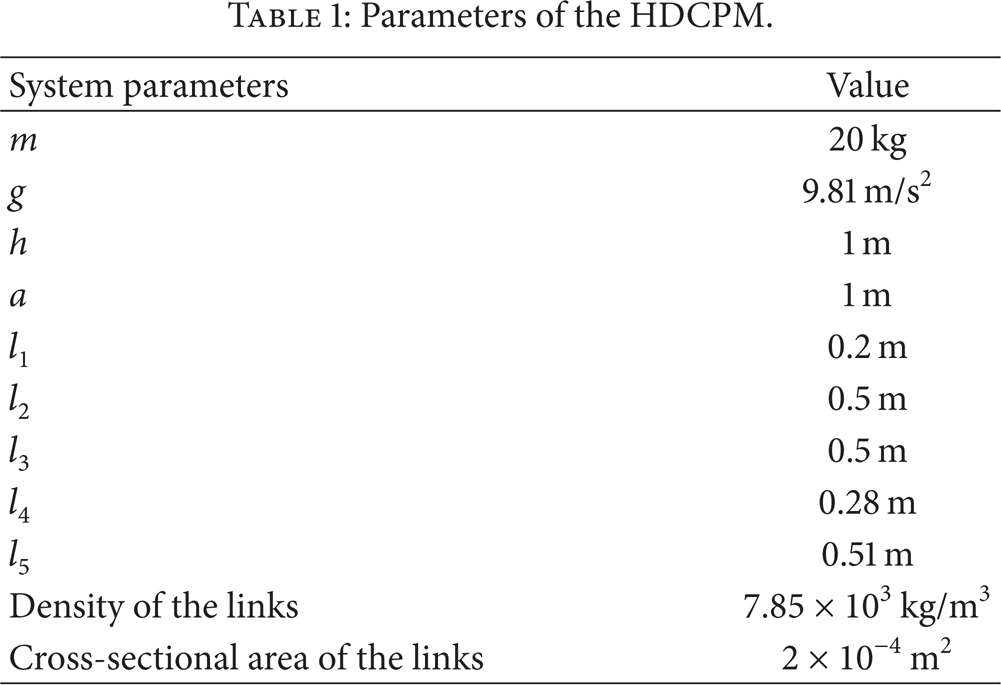
In this section, simulation study is carried out to illustrate the performance of the HDCPM control system. A three-dimensional simulation model of the HDCPM whose schematic sketch is shown in Figure 2 has been established. Three groups of the HDPMs have the same structure parameters and the mechanisms have the symmetrical design in the three-dimensional space. The parameters of the HDCPM are listed in Table 1. In the adaptive iterative learning control method, the control gains are switched from iteration to iteration based on the following rule:
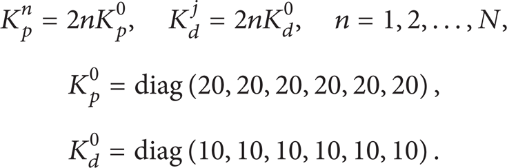
Parameters of the HDCPM.
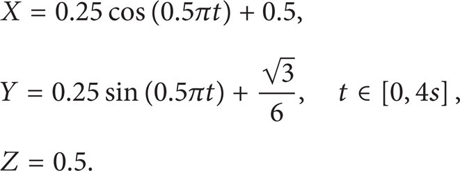
The desired path is selected as
In this example, the random disturbances are
Figure 5 shows the sport demo interface of the HDCPM control system when the end-effector tracks the desired circle trajectory in different time. From the spot demo interface of Figure 5, it can be noted that the HDCPM system runs smoothly, and the movement of all joints is fluent, so by which tracking the desired trajectory movement is accompanied well.

Spot demo interface of the HDCPM: (a) t = 1 s, (b) t = 2 s, (c) t = 3 s, and (d) t = 4 s.
Figure 6 shows the desired trajectory and actual trajectory of the end-effector along the given circle motion path in the different iterations. From it, one can see that the actual trajectory tracks the desired trajectory with high accuracy.

Trajectory tracking of the end-effector.
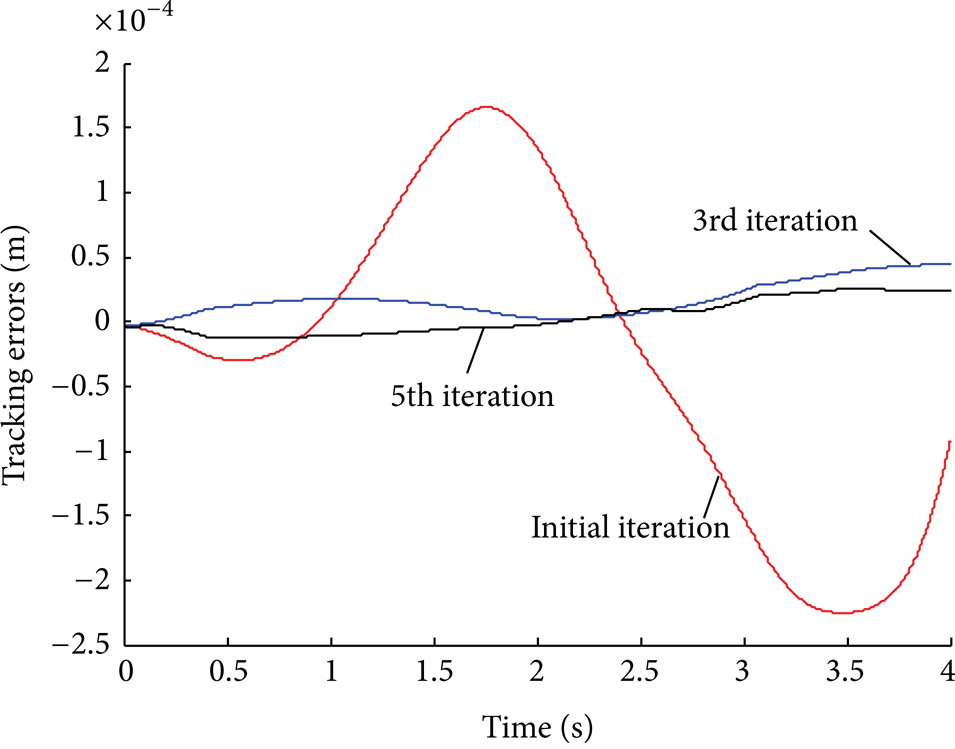
The tracking errors of the end-effector in X, Y, and Z directions under the controller can be seen in Figures 7, 8, and 9, respectively. It is clear that the tracking errors are small and the corresponding tracking performance improvement from iteration to iteration, and eventually could converge close to zero. From the simulations, we can see that the performance of the proposed control strategy is effective for the HDCPM system.
Tracking errors in X-direction.

Tracking errors in Y-direction.

Tracking errors in Z-direction.
Figure 10 shows the desired angular curves and tracking angular curves of the CV motors and servomotors for end-effector tracking in different iterations. It can be seen that the actual angular tracks the desired trajectory with high accuracy.

Angular tracking curves of the CV motors and servomotors in different iterations.
Figure 11 displays the position tracking error curves of the six driving links of three groups of the HDPMs in different iterations. From it one can see that, at the initial iteration, the maximum position errors of the θi1 driven by CV motors are 0.0008, 0.0017, and 0.0007 rad, respectively; the maximum position errors of the θi4 driven by servomotors are 0.0024, 0.0026, and 0.0019 rad, respectively; finally, after five iterations, θi1 is reduced to 0.0003, 0.0001, and 0.0002 rad, respectively; θi4 is reduced to 0.0001, 0.00005, and 0.0001 rad, respectively.
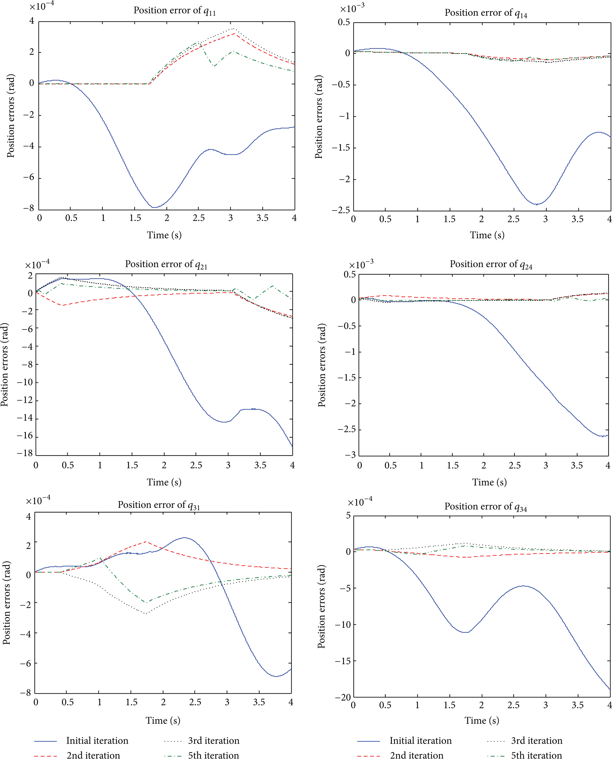
Position tracking error curves of the six driving links in different iterations.
Figure 12 shows the desired curves and tracking curves of cable length in different iterations. It is illustrated in Figure 12, which that shows the cable lengths vary reasonably and are consistent with the desired motion law.

Cable length tracking curves in different iterations.
The driving force of ith cable exerted on the end-effector is defined as a tension cable force T i . Given the total and inertial forces together through every virtual displacement in X, Y, and Z directions, and using the assumptions along with various substitutions and algebraic manipulations of the CPM which are derived, the dynamic model is expressed as

where

is the matrix of coordinate transformer,
Figure 13 depicts the curves of cable tension exerted on the end-effector related to the circle trajectory. Since the end-effector moves on a horizontal circle trajectory, the changes of cable tensions in Figure 13 are reasonable and the transition is smooth.

Cable force tracking curves in different iterations.
Referring to Figures 12 and 13, it should be noted that while the cable length tracking performance is improved from iteration to iteration, the cable forces to drive the end-effector are nearly the same from iteration to iteration after a few iterations. From the above simulation results, it may be concluded that the proposed control system can achieve a relatively favourable control performance and has high robustness.
6. Conclusions
In this paper, iterative learning tracking control of an incompletely restrained HDCPM with three translational motions was presented. The dynamic equation of the whole HDCPM system is addressed. In view of nonlinear, time-varying characteristics and repetitive unknown disturbances of the HDCPM system, a controller incorporates adaptive traditional feedback PD control with iterative learning control which is designed for the high -precision trajectory tracking of the HDCPM system. In addition, the proposed control method is asymptotically stable based on Lyapunov stability analysis. Finally, simulation studies for trajectory tracking control of the HDCPM system illustrate that the dynamic equation is correct and the proposed control method is effective.
Conflict of Interests
The authors declare that there is no conflict of interests regarding the publication of this paper.
Footnotes
Acknowledgments
This work was supported by the National Natural Science Foundation of China (50905179, 51275515) and the State Key Laboratory of Robotics and System (SKLRS-2012-MS-08).