
Abstract
The axle whine noise will eventually affect the vehicle noise performance. In this study, a systematic modeling approach is developed to analyze the axle whine problem by considering the hypoid gear mesh from the tooth contact process as well as the system dynamics effect with gear design parameters and shaft-bearing-housing system taken into account. Moreover, the tuning of the dominant air-borne path is modeled analytically by using the sound transmission loss idea. First, gear tooth load distribution results are obtained in a 3-dimensional loaded tooth contact analysis program. Then mesh parameters are synthesized and applied to a linear multibody gear dynamic model to obtain dynamic mesh and bearing responses. The bearing responses are used as the excitation force to a housing finite element model. Finally, the vibroacoustic analysis of the axle is performed using the boundary element method; sound pressure responses in the axle surface are then simulated. Transmission losses of different panel partitions are included in the final stage to guide the tuning of air-borne paths to reduce the radiated axle whine noise. The proposed approach gives a more in-depth understanding of the axle whine generation and therefore can further facilitate the system design and trouble-shooting.
1. Introduction
There are several noise sources inside a vehicle cabin, such as engine, tire-road, wind, and various electrical components. The engine noise is typically dominant when the engine is in idle or changing speeds. On the other hand, the dominant vehicle interior noise is structure-borne road noise when driving at speed over 30–40 km/h [1]. Those two noises are the primary disturbance annoying the passengers and will significantly influence the perceived quality of the whole vehicle performance. Hence, most of current automotive manufacturers are strengthening more efforts to control and/or tune the engine noise and road noise, either by adopting common refining approaches such as adding mass, tuning stiffness, and damping properties of certain components and designing various types of mufflers or applying novel active noise control techniques [2–8]. It is generally known that the gear whine noises from the transmission and axle systems are normally masked by the dominant engine and road noises. It will, however, become an issue if the noise control methods are targeted to reduce the sound pressure levels of engine and road noises. For instance, several recent observations show that the axle-gear whine noise becomes dominant source in a sport utility vehicle (SUV), especially in a light SUV due to the adoption of light-weighting materials. In order to achieve a better NVH (noise, vibration, and harshness) performance to further fulfill demanding requirements from customers, it is highly desirable to achieve a better understanding of gear axle noise in order to apply certain control techniques to reduce it.
Generally, the gear pair assembly has been considered as one of the major noise and vibration sources in rotating machineries typically seen in automotive, aerospace, and industrial applications [9–12]. The primary excitation force of gear pair vibration is the dynamic mesh force of engaged gear teeth caused by the transmission error (due to tooth profile, spacing error, and elastic deformation of the gear pair). The resultant vibration can be subsequently transmitted through the shaft-bearing system and excite the vibration of housing that radiates annoying noises. The real axle system is widely used in the driveline of SUVs, passenger cars, and light trucks. The hypoid gear pair is the major excitation source inside the gear axle; hence, both structure-borne and air-borne transfer axle whine noises will be transmitted into the interior cabin [13, 14]. Figure 1 gives an illustration of the source-path-receiver analysis of the interior axle whine generation mechanism.

In-vehicle axle whine generation & transmission Scheme.
There have been many research efforts on the dynamic analysis of parallel axis geared rotor systems, but limited investigations can be found on the nonparallel axis gears such as hypoid and bevel gears due to the complex gear geometry and meshing characteristics. Most recently, the research work by Lim's team attempted to reveal the hypoid gear dynamic characteristics. One of the basic frameworks of hypoid gear dynamics was established by Cheng and Lim [15–17], who developed a lumped parameter model based on quasi-static 3-dimensional loaded tooth contact analysis. A single-point mesh model represented by mesh stiffness, mesh point, and line of action was formulated to describe the dynamic coupling between the engaging gear pair. A nonlinear time-varying (NLTV) model took both backlash nonlinearity and time-varying mesh parameters into account. Wang and Lim [18] further developed a multipoint mesh model instead of using a single mesh stiffness coupling for the whole gear pair by constructing an individual mesh stiffness coupling for each tooth pair in contact. As a result, the dynamic mesh force at each individual tooth pair can be obtained. Then, in-depth nonlinear analysis considering the backlash, asymmetric mesh stiffness, and time-varying parameters was conducted by Wang et al. [11, 19] using the harmonic balance method. More recently, Peng [20] proposed the coupled multibody dynamic and vibration model by including the large shaft rotation. Yang et al. [21–23] further investigated the nonlinear dynamic behavior of hypoid gearbox considering a time-varying bearing stiffness and extended to emphasize the whole driveline system by coupling the elastic housing and propeller shaft components.
In spite of these promising successes on the studies of the dynamic analysis of hypoid geared rotor system, there is no reported literature on the systematic study by combing the gear tooth contact analysis all the way down to the vibroacoustic analysis to evaluate and control the radiated axle whine noise. As shown in Figure 1, the interior axle whine noise is due to both structure-borne and air-borne paths. Here, the structure-borne path includes the mounts and suspensions and the air-borne whine noise directly propagates through the floor panel. Recently, Lee et al. [24] conducted a mixed experimental and analytical approach to reduce the axle whine noise by using vibrational transfer path analysis, modal analysis, and operational deflection shape analysis. It was reported that the interior whine noise is dominated by the air-borne noise that transfers from the axle into the passenger compartment. The chassis floor behaves as the dominant transfer path in the air-borne axle whine case. Therefore, traditional path control approaches by using acoustic packages and/or tuning the panel properties to optimize the transmission loss property can be applied. To circumvent the computational cost incurred by numerical approaches such as finite element method and boundary element method for modeling sound transmission loss (STL) through panel partitions, an analytical solution is required. Fortunately, there is a great deal of research papers published recently on analytical modeling of the STL through panels [25–35]. In this study, an analytical model for the transmission loss of single-panel and double-panel systems is developed to couple with the vibroacoustic model of hypoid geared rotor system. Parametric studies are performed to optimize the overall noise reduction performance considering various panel materials and thickness of air cavity.
The organization of this paper is as follows: Section 2 introduces the lumped parameter model for the hypoid gear system. In Section 3, the radiated axle whine noise is estimated through the vibroacoustic analysis using coupled FEM and BEM model. Next, an efficient analytical model is developed for modeling the transmission loss property of chassis panel in Section 4. Finally, a concluded summary is given in Section 5.
2. Geared Rotor Dynamic Model
In this study, a 14-DOF (degree of freedom) lumped parameter model is employed to represent a typical hypoid gear rotor system as shown in Figure 2. The equations of motion for this dynamic system can be developed by applying Lagrange formulation. More detailed derivation and solution of this model can be referred to in several previous studies [10, 20, 36]; the equations of motion in matrix form can be written as

where the coordinate vector is {x} = {θ D , x p , y p , z p , θ px , θ py , θ pz , x g , y g , z g , θ gx , θ gy , θ pxgz , θ L } and the mass matrix is [M] = diag[I D , M p , M p , M p , I px , I py , I pz , M g , M g , M g , I gx , I gy , I gz , I L ], and [K] and [C] are stiffness and damping matrices. The gyroscopic matrices [G] and [G a ] are associated with the absolute rolling velocities and accelerations of pinion and gear, respectively.

14-DOF hypoid geared rotor system model.
Some parameters in the above equations can be derived from the gear contact cells model shown in Figure 3. The position vector of the contact cell in the mesh coordinate system is r i (r ix , r iy , r iz ), the contact force is f i , and the normal vector is n i (n ix , n iy , n iz ). The total contact force is calculated by summing the contact forces on each contact cell (assuming there are N contact cells):

The line-of-action vector L(n x , n y , n z ) can be obtained from
The total contact moment is given by

The mesh point R(x m , y m , z m ) can be obtained from


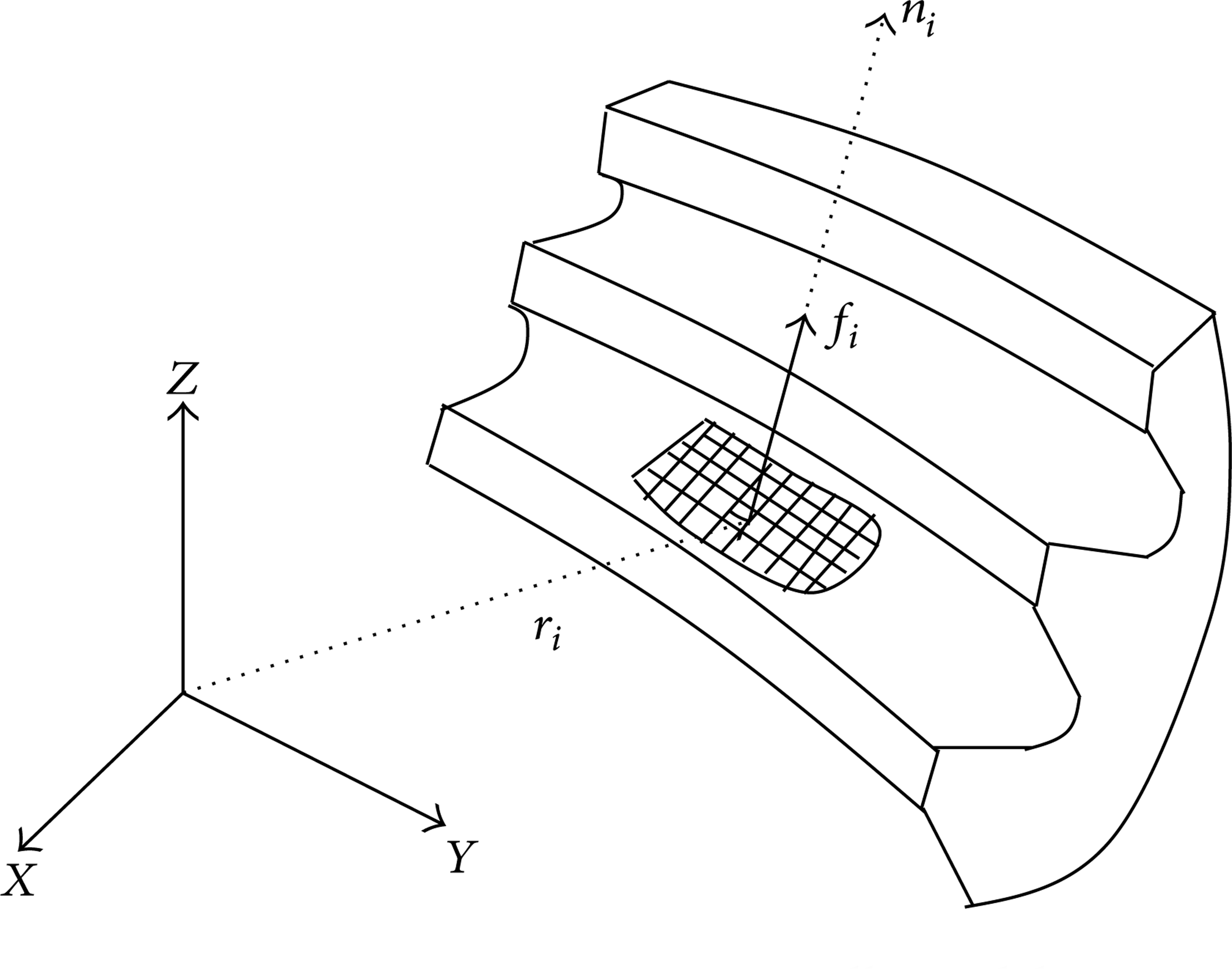
Basic gear contact cells model.
The translational loaded and unloaded transmission errors e L and e0 are the projections of corresponding angular transmission error along the line of action. Finally, the mesh stiffness is defined by

The dynamic mesh force F m is

where b c is the gear backlash, ε0 is unloaded transmission error, and rotational radius is defined as

where L i and R i are the line of action and mesh point in pinion coordinate system (l = p) or gear coordinate system (l = g) and X l , Y l , Z l are the unit vectors in the pinion or gear coordinate system.
Finally, the dynamic transmission error δ d is given by

The parameters k m , c m , and ε0 are obtained from multipoint mesh model; thus the dynamic mesh force for each contact gear pair can be calculated.
3. Radiated Axle Noise
To predict the radiated axle whine noise, a combination of finite element method (FEM) and boundary element method (BEM) were used. The FE model of the axle housing is shown in Figure 4. It should be noted that in order to improve the computation efficiency, some small geometry structures, like fillet and chamfer, are eliminated in the FE model. The mode shapes and natural frequencies of the axle housing structure are first calculated by using Lanczos method. Then the forced vibration response of the axle housing is calculated by using the modal superposition method. The frequency range of interest covers a broadband from 100 Hz to 4000 Hz and the frequency incremental step is 10 Hz.

Axle housing FEM model.
For the axle whine noise estimation, the Coustyx (made by ANSOL) was used as the solver for calculating exterior radiated noise [37]. This tool can efficiently estimate the acoustic radiation of a gearbox to high frequency regime. The axle housing BEM model is shown in Figure 5. This model consists of 9491 elements and 18894 nodes and satisfies the classical 5 or 6 elements per wavelength criterion up to 4000 Hz. The axle housing surface vibrating velocity response is applied as the BEM model boundary condition. The sound power is calculated using hemisphere measurement surface according to ISO3745 and the result is shown in Figure 6. The classic automotive hypoid gear set design parameters are listed in Table 1. The 14-DOF gear rotor system dynamics parameters are listed in Table 2.
Base case design parameters.

Dynamic model parameters.


Axle housing BEM model.

The predicted axle noise.
4. Transmission Loss Modeling
In this section, transmission loss characteristics of the vehicle chassis panel are analyzed to facilitate the design of system components to reduce the air-borne axle noise transmitted into the interior cabin. To circumvent the computational cost incurred by numerical approaches such as finite element method and boundary element method, an analytical approach is adopted to model the sound transmission loss through panel partitions. Furthermore, parametric studies are conducted to illustrate the effect of panel parameters such as material, thickness, and inclusion of air cavity on the transmission loss. This methodology can be easily coupled with the above-proposed systematic hypoid gear dynamic and axle radiated noise simulation scheme.
4.1. Single Panel
The following mathematical derivations are based on the original study proposed by Roussos [25]. The vehicle floor panel over the rear axle is modeled as a simply-supported flexible plate. The plate is assumed to be infinitely baffled, where the incident sound waves will purely excite the vibration of the plate that radiates noise into the transmitted sound field. The governing equation of motion for the single-panel system can be described as

where S = (Eh3/12(1 − v2))∇4 is a linear differential operator, m = ρh is the area density of the panel (ρh are the material density and thickness of the panel),

where the blocked pressure p
b
is twice the incident pressure (
where I is the amplitude of the incident pressure and k x = k0sinφcos θ, k y = k0sinφsinθ are the wave number components in the directions of x, y. Here, k0 = ω/c0 denotes the wave number in air, ω is the angular frequency, c0 is the acoustic speed in air, and φ and θ are the elevation and azimuth angles presenting direction of the uniform plane sound wave impinging on the panel. At this point, the incident sound power can be calculated as

where L x and L y are the dimensions of the rectangular plate and ρ0 is the air density. Next, the power of transmitted sound power can be calculated by solving the panel equation of motion and radiated sound field due to the surface velocity of the panel. The EOM of panel can be further simplified by using modal superposition approach as

where

where u m and v m are the mth mode indices in two directions. It is assumed further that the boundary condition of the acoustic pressure and panel vibrational responses should be compatible under the steady-state solution:

where P m is the generalized forcing pressure, given by
By substituting (16) and (17) into (14), the generalized displacements W m can be solved.
Next, the transmitted sound pressure due to the vibration of the panel can be represented by using Rayleigh integral as

where r is the displacement from the vibration surface to the point in the radiated sound field. Detailed derivation can be seen from the reference paper, and the radiated sound power can be expressed in terms of the generalized displacements of the vibrating panel:

Finally, the transmission loss (TL) is defined as
4.2. Double Panel
The modeling of transmission loss for double panels enclosed with air cavity can be calculated from the formulation proposed by Xin et al. [31]. The double panel with enclosed air cavity system is located in an infinite baffle. The mathematical derivation is very similar to the derivation introduced in the above section; here the governing equations of motion of the two simply-supported plates are considered:
where

where Φ i is the velocity potentials and the relation between velocity potential and pressure fields can be expressed as

Similarly, the modal superposition approach is applied to solve the EOM of two panels. Here the flexural displacements of bottom and upper panels excited by a harmonic sound wave can be expressed as that shown in (15). The modal equations of the panels are described as

where


where the unknown coefficients I m , β m , ε m , and ζ m are expressed in the same form as (17). As shown in the reference paper, these four terms are related to the generalized displacements W m 1, W m 2 by following the velocity compatibility conditions. Finally, the modal equation (24) can be further simplified as matrix equations in each frequency ω, and the sound transmission coefficient is defined as

And the sound transmission loss across the double-panel partition is inverse of the power transmission coefficient:

4.3. Results and Discussions
Numerical simulations were conducted to model the STL through panel partitions based on the analytical model adopted in this study. The vehicle floor panel is simplified as 0.4 m by 0.4 m square plate and simply supported in an infinite acoustic baffle. The thickness of the panel is 3 mm, and the thickness of the enclosed air cavity is 2 cm. Note that the double-panel system with cavity is assumed to simulate wrapping an aluminum panel onto the steel body when in practical applications. Also, the STL model applied in this study can be easily implemented to model the sound transmission property through the door frame that is typically panel partitions with a large enclosed air cavity. The approach will facilitate the acoustic design of driveline and body frame in an early stage.
Figure 7 shows the comparison of the transmission loss for a single-panel system with different panel materials. Here modal damping with ε = 0.05 was added in the modal EOM of the panel. It can be seen that the steel panel has a higher transmission loss value than the aluminum. The first dip in the frequency around 100 Hz is due to the resonant vibrational mode of the panel, which means most of the acoustic waves will transmit through the panel. Figure 8 presents the effect of panel thickness on the STL curve; here the material is aluminum. The thin solid line is thickness of 3 mm, the dash dotted line is 2 mm, and the bold dotted one is 4 mm. It is noted that the mass law controls the overall sound insulation property and the STL values increase as the panel thickness is increased. Hence, it requires more careful sound insulation performance design in the development of light-weight vehicle chassis panel. For instance, the STL values might drop drastically when adopting light alloy materials or other composites. Figure 9 gives the estimated axle noise after the reduction of single steel panel. We can see that most of the dominant tonal peaks are reduced to nonaudible (below 0 dB) with simple adoption of single-layer steel panel. This is consistent with the practical axle whine noise problem since the air-borne noise can be well treated without affecting the overall interior sound quality. However, the STL of chassis panel still needs to well design a light SUV that might have a very poor acoustic package.

Transmission loss of a single panel with different materials.
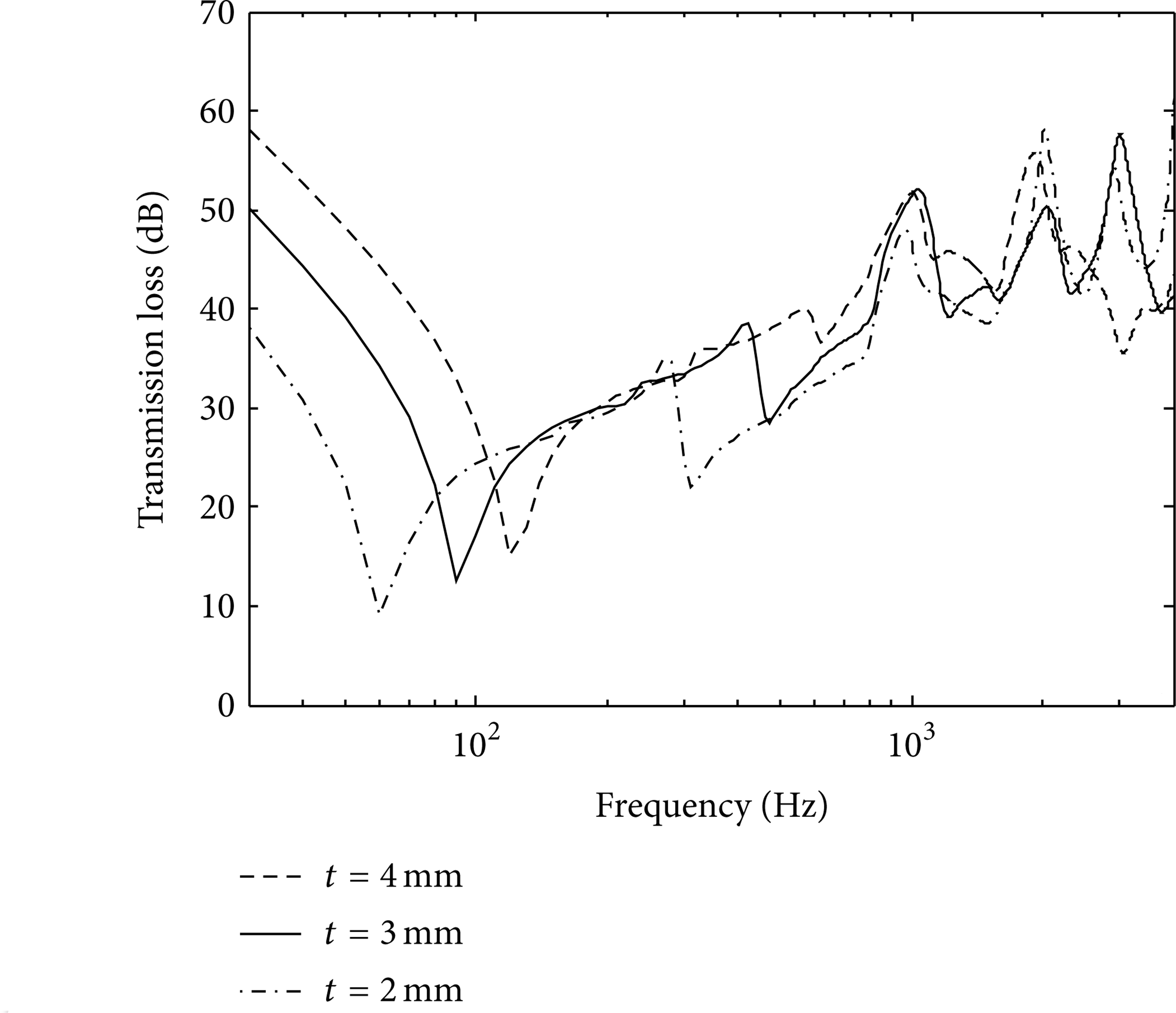
Effect of panel thickness on the transmission loss for a single aluminum panel.

Reduction of the radiated axle whine noise after a single steel panel.
Next, sound transmission loss property through double panel with air cavity is studied. Here, the inclusion of air cavity is used to simulate the covering of vehicle chassis with a thin aluminum or other light-weight materials. Figure 10 shows the comparison of transmission loss for the single-panel and double-panel partition systems. It can be seen that the sound insulation property is significantly increased for the double panel with cavity, especially in the lower and higher frequency range. Note that the STL performance is primarily controlled by the vibration of panel while the double-panel system is more complex since there are mass-air-mass mode and standing wave mode. The enclosed air cavity can be considered as a spring with certain stiffness and the panel is with mass; hence for some frequency points, the modes of the mass-spring-mass system will dominate. In addition, the wave transmitted through bottom panel and reflected by the top panel will superimpose and become a standing wave. The thickness of the air cavity and the frequency or wavelength will determine the standing wave resonances. Similarly, the transmitted axle noise after the double-panel system is calculated by simple mathematical formulation, as shown in Figure 11. It is obviously seen that the overall noise reduction performance is significantly improved with the application of double-panel partition system. For the lower frequency, the resonances of panel-cavity-panel lead to the dip of TL curves which can be further tuned by adding more damping.
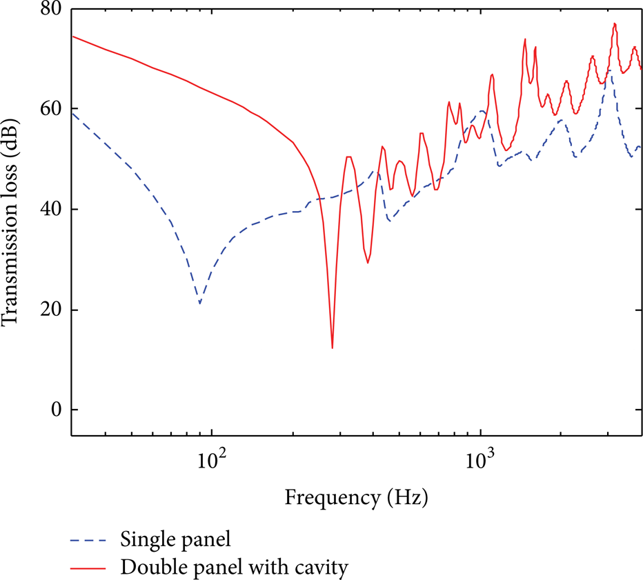
Transmission loss comparison of a single panel and double panel with enclosed air cavity (note the depth of air cavity H = 2 cm).

Reduction of the radiated axle whine noise after the double panel with enclosed air cavity.
Figure 12 shows the parametric study of the effect of cavity thickness on the TL of double-panel system. The positions of the first mass-air-mass mode shift to lower frequencies with increasing of the air cavity thickness. Also, there is certain increase in the high frequency range since the increase of the air gap yields more insulation. Here, it can be implied that the overall sound insulation performance can be tuned by tailoring the depth of the air cavity. Moreover, the thickness of each panel can be tuned to optimize the noise reduction performance. The idea of using double-panel partitions has been widely used in the body structure of high-speed train, some components on vehicle body, and aerospace industry. On the other hand, it might be more complicated to directly apply the double-panel partition into the vehicle chassis. However, it might be practical to add thin cover to the vehicle floor panel. In summary, the systematic approach proposed in this study gives a solution for the design and optimization of axle system and air-borne noise transmission through chassis panel.

Effect of air cavity thickness on the transmission loss for the double-panel system.
5. Conclusions
In this paper, a systematic approach is proposed to model the gear whine noise generation by considering the hypoid gear mesh via the tooth contact analysis and the subsequent system dynamic effect by modeling the shaft-bearing-housing-axle components. The dominant air-borne transfer path is modeled by using the sound transmission loss idea considering different panel partitions, material properties, and thickness and air cavity depths. In the first part, a 14-DOF hypoid gear dynamic model is constructed by using a lumped parameter model where the gear meshing parameters were calculated from a 3D tooth contact analysis program. The bearing forces were calculated and used as an input into the FEM model of the housing-axle structure, where the surface velocity can be computed. Then, the BEM approach was conducted to predict the radiated gear axle whine noise. Finally, the modeling of transmission loss for the floor panel was directly formulated in an analytical form and applied for predicting the interior air-borne axle whine noise. Various system parameters can be tuned to optimize the procedure to reduce the whine noise. The systematic modeling approach gives an idea of understanding the gear axle whine noise generation and can be further coupled with a more real driveline system. Also, the practical air-borne and structure-borne transfer path analysis will be conducted in the future on a light SUV to pinpoint the noise and vibration issue.
Conflict of Interests
The authors declare that there is no conflict of interests regarding the publication of this paper.
Footnotes
Acknowledgments
The authors wish to express grateful thanks to the China Scholarship Council (CSC). This work is also completed as part of the collaboration with the College of Engineering and Applied Science at the University of Cincinnati.