
Abstract
In order to obtain better vibration suppression effect, this paper designs a semiactive/fully active hybrid isolator by using magnetorheological elastomer (MRE) and piezoelectric material. Combined with multimode control scheme, full frequency vibration suppression is achieved. Firstly, series type structure is determined for the hybrid isolator, and the structure of hybrid isolator is designed. Next, the dynamic model of hybrid isolator is derived, the dynamic characteristics measurement for MRE isolator and piezoelectric stack actuator (PSA) is established, and parameters such as voltage-displacement coefficient, stiffness and damping constant are identified from the experimental results, respectively. Meanwhile, the switch frequency is determined by experimental results of PSA and MRE isolator. Lastly, influence of the stiffness of MRE, control voltage of PSA, and intermediate mass on hybrid isolator system is analyzed by simulations, and the results show that the hybrid isolator proposed is effective.
1. Introduction
Along with the development of micro-nano-fabrication and precision measurement technology, how to reduce effectively the adverse effects of vibration has become a difficult and hot problem [1]. The vibration frequency, which is brought by earth's rotation and change of earth's crust, is 0-1 Hz, building swinging is 10–100 Hz, transformer and motor are 6–65 Hz, and occupant movement is 1–3 Hz. So the frequency range of vibration suppressed is 0–100 Hz. The existing microvibration control methods mainly include active [2] and passive [3] vibration isolation methods. However, the two methods have some disadvantages. The active one includes piezoelectric actuators [4–6] and electromagnetic actuators [7–10]. Among the active elements, the piezoelectric actuator features fast response speed, small stroke, compact structure, and high force generation. However, it has large energy consumption, poor stability, and high frequency suppression effects. Correspondingly, the passive one such as rubber has poor low frequency suppression effects.
Combining the advantage of active control and passive vibration isolation, full-active/passive hybrid isolation is employed to avoid the disadvantages of the two isolation methods. Moshrefi-Torbati et al. [11] designed a kind of hybrid isolator to prevent the high-tech precision instrument from being damaged in space structures. Young et al. studied active control with the piezoelectric actuators and passive interaction of composite beams [12]. Lin realized the hierarchical control of active and passive piezoelectric actuator via fuzzy vibration control method [13]. Jang et al. [14] propose a new hybrid mount system with air springs and PSA, and the results show that the hybrid mount had excellent performance in the microvibration control of high-tech facilities. However, when passive control of hybrid isolation technology is actuated to implement passive vibration control, the damping and stiffness of the system are not adjustable, so there is bad effect of vibration isolation under the changing of external excitation frequency. The appearance of the magnetorheological materials provides a new way for the vibration isolation technique.
Isolator based on magnetorheological material belongs to semiactive type, which requires less energy to generate the control magnetic field. And the vibration can be suppressed by adjusting the damping or stiffness coefficient of the isolator. It has advantages such as fast response time (in milliseconds), wide range, and good reversibility, which has been applied to vehicle suspension [15], civil construction [16], and so forth; MRE is a new branch of magnetorheological materials, which is composed of polymer and ferromagnetic particles. The shear modulus and loss modulus of MRE can be controlled by applying the real-time magnetic field strength [17–19]. Compared with the magnetorheological fluid, MRE overcomes the problem of poor stability, easy settlement, and easy leakage and has a broad application prospect in engine vibration isolation [20], intelligent vibration absorber [21], and so forth. Experiments show that MRE with small strain can obtain more obvious magnetorheological effect and better controllability [22]. Therefore, MRE is more suitable for the inhibition of microvibration.
In view of the above problems, this paper proposes the semiactive/fully active hybrid isolator with combination between MRE and PSA, which corresponds to the combination between many “passive” isolators and active vibration isolator, and the “passive” isolator can be adjusted arbitrarily with some stiffness and damping. The additional magnetic field changes the stiffness and damping parameters of MRE isolator. By switch control between MRE isolator and PSA, full frequency vibration is suppressed. In this paper, the series type structure of hybrid isolator is determined and designed. The dynamic model of hybrid isolator is established, then the dynamic characteristics measurement for MRE isolator and PSA is established, the switch frequency is obtained, and parameters such as voltage-displacement coefficient and stiffness and damping constants are identified from the experimental results, respectively. Simulations of switch control for MRE isolator and PSA are established to verify the effect of the proposed hybrid isolator. The micro-vibration control method proposed in this paper is a helpful exploration, which covers the stability, the controllability, and the advantages of good dynamic characteristics and large output force, realizes the effective attenuation band of all band microvibrations including ultralow frequency vibration, and solves the vibration problems of micronanoprocessing caused by uncertain excitation. Meanwhile, the volume and quality of vibration isolator can be reduced.
2. The Structure of Hybrid Isolator
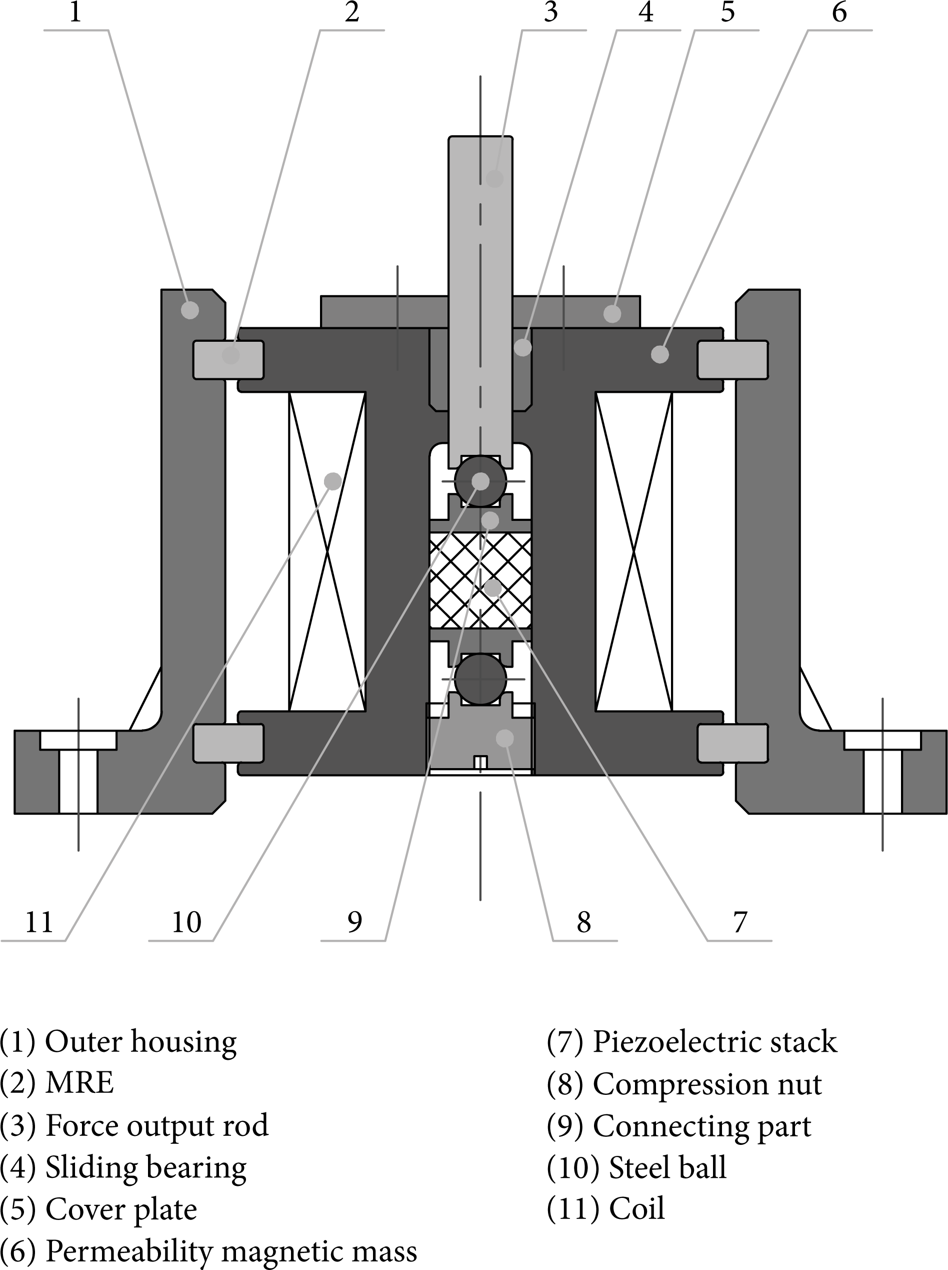
The designed hybrid isolator is made to suppress the vertical vibration by MRE and PSA in series type structure, and the scheme is shown in Figure 1, which consists of eleven parts. The hybrid isolator is used to micro-nano-fabrication platform, which is shown in Figure 2. The principle of the hybrid isolator is described as follows.
Scheme of designed hybrid isolator.
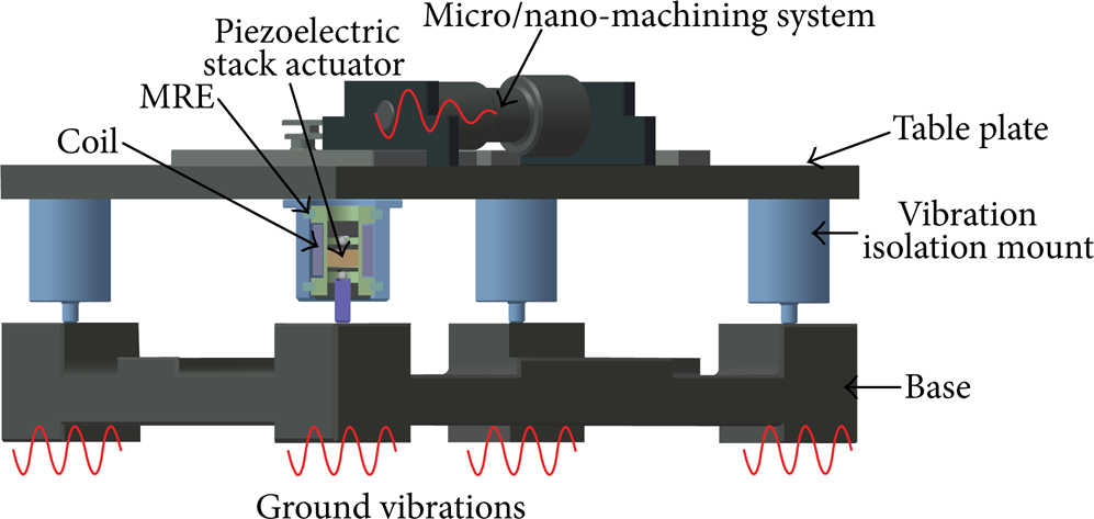
Scheme of micro-nano-fabrication platform.
Under low-frequency excitations, the piezoelectric stack is actuated to implement active vibration control while the stiffness of the controlled MRE is constant, which can be regarded as a passive vibration isolation device. The excitation displacement restricted by the vibration isolation system will generate excitation force. The piezoelectric stack 7 shown in Figure 1 under the control voltage generates an axial force, which pushes the force output rod 3 to cancel the excitation force. The low-frequency excitations are thus controlled. The torque induced in the assembly process is eliminated by the steel ball 10 to protect the piezoelectric stack from damage.
Under high-frequency excitations, MRE is actuated to implement semiactive vibration control while the piezoelectric stack can be regarded as a rigid component, the stiffness of which is constant. Since the coil 11 carries the exciting current, permeability magnetic mass 6, MRE in shear mode 2, and outer housing 1 form a closed magnetic circuit. The storage shear modulus and loss modulus of MRE controlled by the excitation magnetic field modify the stiffness and damping characteristic of the structure, which results in changes in the resonant frequency and vibration decay rate of the system. The control algorithm for excitations with different frequencies and amplitudes is designed to obtain appropriate exciting current to attenuate actively the high-frequency vibration.
3. Dynamic Model of Hybrid Isolator
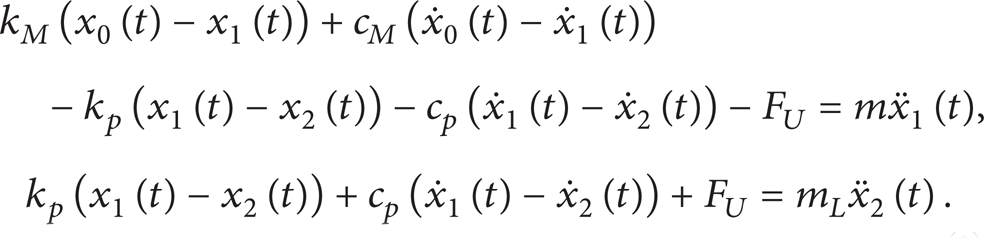
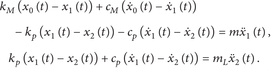
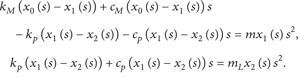
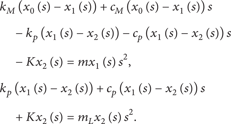
The mechanical model of the hybrid vibration isolator, which consists of PSA, intermediate mass, and MRE, is shown in Figure 3. In Figure 3, k p and c p are the stiffness and damping constant of the piezoelectric stack actuator, k M and c M are the stiffness and damping constant of the MRE, m L and m are the load and intermediate mass, x0(t) is the displacement transmitted from base, x1(t) and x2(t) are the displacements of the intermediate mass and load, and F U is the force generated by the PSA under the control voltage. The equations of motion of the hybrid isolator can be obtained from Figure 3 as follows:

Dynamic model of hybrid isolator.
It is important to study the dynamic characteristics and obtain the parameters of hybrid isolation system. However, for there is a coupling relationship between PSA and MRE isolator, it is difficult to obtain the parameters of hybrid isolation system experimentally. So MRE isolator and PSA are studied experimentally, respectively, in the following, which is an approximation to hybrid system in series.
4. Parameters Identification of PSA
Based on inverse piezoelectric effect, the actuating force of the PSA is given in the following [23]:

where F is the actuating force generated by the actuator, Δl is the practical displacement of the actuator, Δl0 is the displacement of the actuator without mechanical load, k p is the stiffness, F U is the force exerted by the voltage, and α is defined as the voltage-displacement coefficient. The equation states that the restriction of output displacement results in the actuating force.
4.1. Voltage-Displacement Coefficient Identification
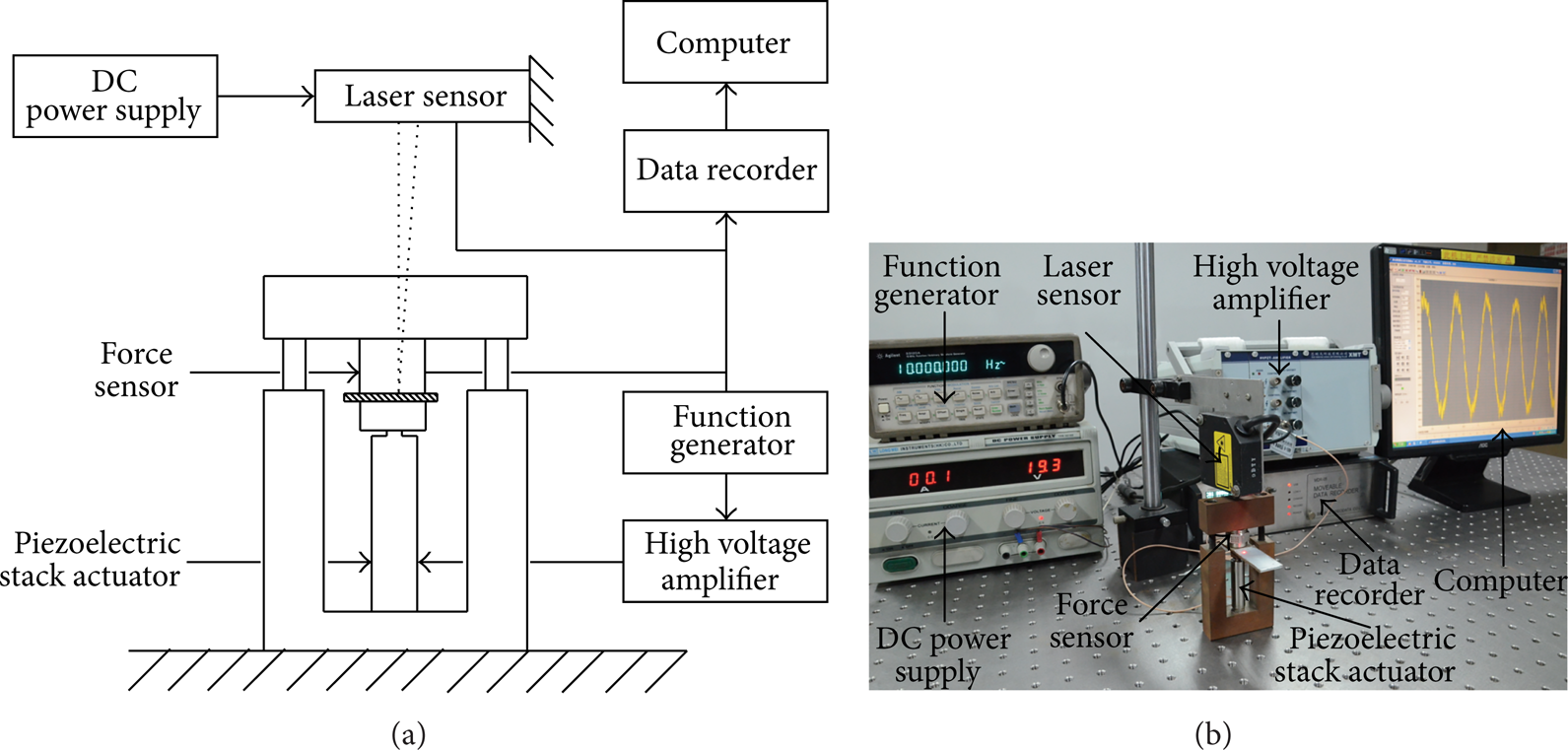
Experimental setup without mechanical load is established as shown in Figure 4, which is used to identify the voltage-displacement coefficient of piezoelectric stack actuator.

Experimental setup for the dynamic characteristics measurement of PSA without mechanical load: (a) schematic configuration and (b) photograph.
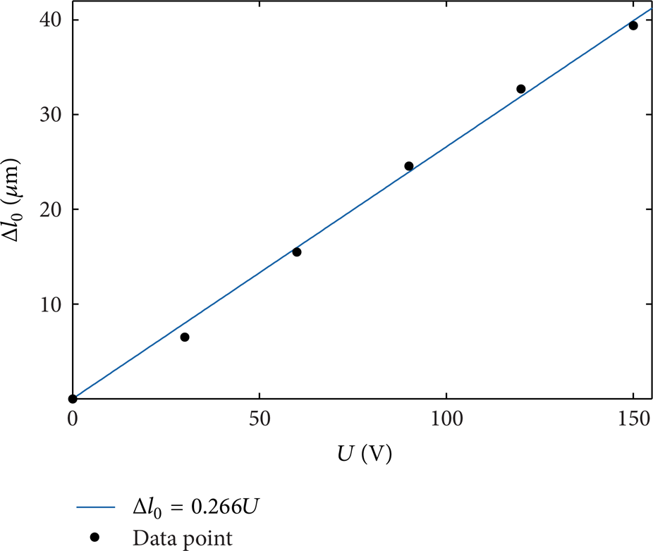
The sinusoidal voltage with a bias is applied to the actuator, and Figure 5 presents the magnitude-frequency response of the displacement of the actuator without mechanical load. It can be seen from Figure 5 that the curves are approximately straight lines, which indicates that the displacement of the actuator is independent of the frequency of the input voltage with the range of 50 Hz. And the displacement increases as the voltage increases. The displacement of the actuator under different voltages can be acquired from Figure 5, which is shown in Table 1. The voltage-displacement coefficient is obtained by the linear fitting from Table 1, which is shown in Figure 6. The fitting equation is Δl0 = 0.266U, so the coefficient is α = 0.266 μm/V.
Displacement of the actuator under different voltages without mechanical load.


Magnitude-frequency response of displacement of PSA without mechanical load.
Linear fitting result.
4.2. Stiffness Identification
Experimental setup with mechanical load is established as shown in Figure 7, which is used to identify the stiffness of piezoelectric stack actuator. The clamping structure is used to restrict the displacement of the actuator. The working process of the experimental setup is similar to the one introduced above.
Experimental setup for the dynamic characteristics measurement of the actuator with mechanical load: (a) schematic configuration and (b) photograph.
Both force and displacement are generated by the actuator with mechanical load. The magnitude-frequency response of the output force of the actuator with mechanical load is shown in Figure 8. It can be seen that the force increases as the voltage increases within the frequency range of 50 Hz. The curves in Figure 8 declined in the low frequency range, which is caused by the deficient low-frequency performance of the piezoelectric force sensor (Type 5110, CALT, China) used in this paper.

Magnitude-frequency response of output force of PSA with mechanical load under different voltages.
The curve of the force displacement of the actuator is drawn in Figure 9. It can be known from (2) that the points with mechanical load and unload are the two endpoints of the curve, respectively. The slope of the force-displacement curve is the stiffness of the actuator. The stiffness of the actuator under different voltages is shown in Table 2, and the average value is regarded as the true value of the stiffness.
Stiffness of PSA under different voltages.


Force-displacement curves of PSA under different voltages.
4.3. Damping Constant Identification
In order to identify the damping constant, the experiment of step response of the actuator is established, in which the square signal is used to generate step signal. And the experimental setup is similar to that of above. The normalization result is shown in Figure 10. It can be clearly seen that the actuator system is an overdamped second order system. The transfer function is given in the following:

where

Normalization result of the step response.
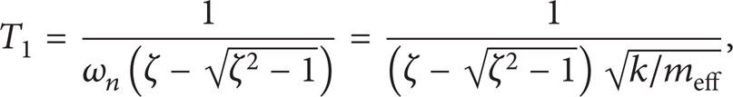
The setting time of the step response of the actuator t s is as follows [24]:

In order to obtain the damping constant, the hypothesis method is employed in the following. It is assumed that the ratio β approaches infinity, and then (4) can be written as

That is, t s /T1 = 3. It can be known from Figure 8 that the setting time t s is 4.1554 ms, so the time constant is T1 = 1.3851 ms. For
where meff is the effective mass of the PSA, which is one-third of the mass for a unilaterally clamped PSA, the mass of the PSA used in this paper is 25.4 g, and the effective mass meff = 8.5 g. So the damping ratio is ζ = 34.1861.
Submitting ζ = 34.1861 into
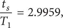
which is equivalent to the assumption t s /T1 = 3.
So the assumption is valid, and the damping constant is as follows:

Then the damping constant c p is 2.8681 × 10⁴ N·s/m.
The comparison between experimental and simulation results of step response is shown in Figure 11. It can be seen from Figure 11 that the steady state results are similar, so the model is effective. But there is an error in the dynamic process. The reason lies in the relatively narrow bandwidth of the experimental setup, and the high frequency component of the displacement signal cannot be collected. So the experimental result in Figure 11 does not respond as fast as the simulation result.

Comparison between experimental and simulation results.
Remark 1. In general, the delay time, rising time, and setting time of the step response are all used to identify the damping constant of the system. However, it is clearly shown in Figure 11 that setting time should be chosen for identification, rather than delay time or rising time.
5. Parameters Identification of MRE Isolator
The scheme of MRE isolator designed is shown in Figure 12, which consists of MRE, iron core, sleeve, coil, and base, where the iron core, MRE, sleeve, and coil constitute closed-loop magnetic circuit, which can reduce the leakage of magnetic field. So the designed isolator can enlarge the shear area effectively and enhance the structural-load-carrying capacity. Two MREs are clung to both the iron core and sleeve. The MRE operates on shear mode with excitation application. The magnetic field can be controlled by applied current in the coil, which makes stiffness of MRE controllable.

Structure of MRE.
Remark 2. For stiffness of MRE can be controlled by magnetic field, when the magnetic circuit is designed, the simple structure and magnetic flux leakage should be considered.
The experimental platform has been set up, which is shown in Figure 13. The test system includes the MRE isolator, acceleration sensor, electromagnetic vibration table, and data acquisition instrument. A sinusoidal steady-state sweep frequency is selected to test the property of MRE isolator. A logarithmic sweep frequency mode is set from 10 Hz to 100 Hz in a cycle. The excitation and response acceleration signal of MRE isolator under 0-1 A currents are shown in Figures 14 and 15, respectively. It is noted that maximum peak-to-peak value of displacement is 0.2 mm.

The testing device.

The excitation signal of experimental device under sine sweep.

The response signal of experimental device under sine sweep.
The transmissibility with acceleration input for input electric currents ranging from 0 to 1 A is shown in Figure 16, which is calculated by the ratio between output amplitude obtained by Figure 15 and excitation amplitude obtained by Figure 14. From Figure 16 the following can be obtained.
The transmissibility is attenuated with the increasing of applied current. Compared with the transmissibility with 0 A, the decrement of the transmissibility with 1 A is 51.6%.
The natural frequency increases with the increasing of applied current due to the changes of MRE stiffness under the applied current; the natural frequency is 40 Hz and 60 Hz with 0 A and 1 A, and the increment is 50%.
The resonance peak decreases obviously with the increasing of applied current, which is caused by the increasing damping.
Next, by kinetic equation, we can get the transfer function of MRE isolator system as follows:

where η is the ratio of the excitation frequency and the natural frequency of MRE isolator; the natural frequency is expressed as follows:

So the stiffness coefficient can be obtained as follows:


The vibration transmissibility of experimental device under sine sweep.
The sprung mass m s is 1.7 kg, Tr is chosen for transmission from Figure 16, so η = 1. f n is the resonance frequency which can be obtained from Figure 16. From formula (9) to (12), the stiffness and damping coefficient of MRE isolator under different currents can be given in Table 3.
Stiffness and damping constants of the MRE under different currents.

6. Influence of Parameters on Dynamic Characteristics of Hybrid Isolator
6.1. Influence of the Stiffness of MRE on Dynamic Characteristics of Hybrid Isolator
Under high-frequency excitations, MRE is actuated to implement semiactive vibration control while the piezoelectric stack can be regarded as a rigid component, the stiffness and damping constant of which are constant. So, the force generated by the piezoelectric stack actuator F U = 0. From Figure 3, it can be known that the equations of motion of the isolator under high-frequency excitations are as follows:
Take the Laplace transform for the above equations, which can be obtained as follows:
The transfer function between x1(t) and x0(t) is as follows:
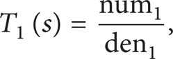
where num1 = (k M + c M s)(k p + c p s + m L s2) and den1 = k M k p + (k M c p + c M k p )s + (k M m L + c M c p + k p m L + mk p )s2 + (c M m L + c p m L + mc p )s3 + mm L s4.
The transfer function between x2(t) and x1(t) is as follows:

The transfer function between x2(t) and x0(t) is as follows:

where num = k M k p + (c M k p + k M c p )s + c M c p s2 and den = k M k p + (k M c p + c M k p )s + (k M m L + c M c p + k p m L + mk p )s2 + (c M m L + c p m L + mc p )s3 + mm L s4.
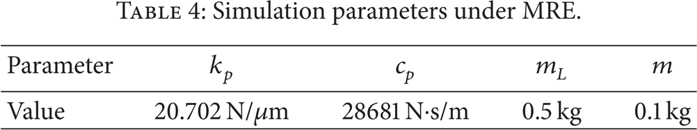
The parameters for simulation are given in Table 4. Based on Tables 3 and 4, the transfer functions of the isolator under different currents can be obtained, and the bode graphs are shown in Figure 17. And the amplitude-frequency curves are the transmissibility-frequency curves of the isolator. It can be seen from Figure 17 that the resonant frequency of the isolator increases with the increase of the current and the transmissibility shows the opposite trend, and the resonant frequency is 60 Hz and 95 Hz with 0 A and 1 A. So the MRE isolator can suppress the vibration of high frequency with 50–100 Hz.
Simulation parameters under MRE.
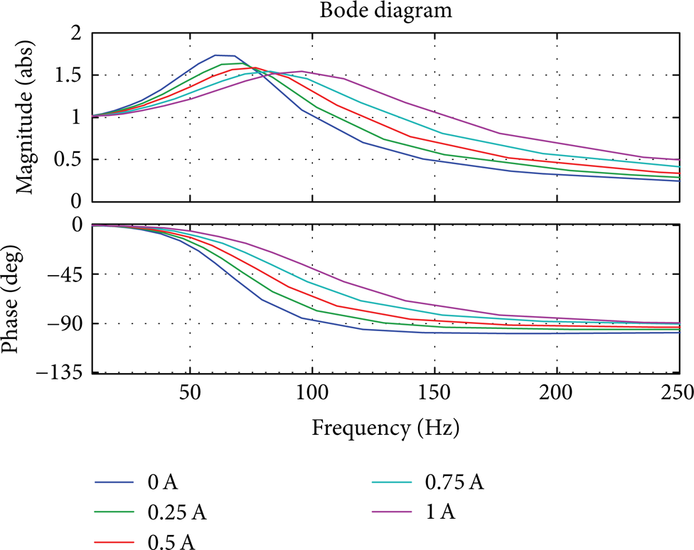
Bode graphs of the hybrid isolator under different currents.
6.2. Influence of the Intermediate Mass on Dynamic Characteristics of Hybrid Isolator
For system presented by (13) of motion, the bode graphs of the hybrid isolator under different intermediate mass are simulated to show the influence of the intermediate mass, which is shown in Figure 18. In the simulation process, the exciting current is set to 1 A, and other parameters are given in Tables 3 and 4. The amplitude-frequency curves are the transmissibility-frequency curves of the isolator. It can be seen from Figure 18 that the mass is in proportion to the transmissibility and in inverse proportion to the resonant frequency. Thus a relatively small intermediate mass should be chosen for the manufacture of the hybrid isolator.

Bode graphs of the hybrid isolator under different intermediate mass.
6.3. Influence of Control Voltage of PSA on Dynamic Characteristics of Hybrid Isolator
Under low-frequency excitations, the piezoelectric stack is actuated to implement active vibration control while the stiffness and damping constants of the uncontrolled MRE are constant, which can be regarded as a passive vibration isolation device. The state feedback controller is designed to attenuate the vibration, so the force generated by the PSA is F U = Kx2(t), where K is the state feedback coefficient. The equations of motion of the isolator under low-frequency excitations are as follows:

Take the Laplace transform for the above equations, which can be obtained as follows:
The transfer function between x1(t) and x0(t) is as follows:

where num1 = (k M + c M s)(k p − K + c p s + m L s2) and den1 = k M k p − k M K + (k M c p + c M k p − c M K)s + (k M m L + c M c p + k p m L + mk p − mk)s2 + (c M m L + c p m L + mc p )s3 + mm L s4.
The transfer function between x2(t) and x1(t) is as follows:

The transfer function between x2(t) and x0(t) is as follows:

where num = k M k p + (c M k p + k M c p )s + c M c p s2 and den = k M k p − k M K + (k M c p + c M k p − c M K)s + (k M m L + c M c p + k p m L + mk p − mk)s2 + (c M m L + c p m L + mc p )s3 + mm L s4.
The force F U and displacement x2(t) should be in opposite directions to attenuate the vibration, so the state feedback coefficient K is negative. As shown in Figure 19, the bode graphs of the system under different state feedback coefficients are simulated to show the influence of the state feedback coefficient on the dynamic characteristics of the system. Simulation parameters are given in Table 5, and the amplitude-frequency curves are the transmissibility-frequency curves of the system. It can be seen from Figure 19 that the larger the absolute value of K, the smaller the transmissibility under one certain frequency, and the better the vibration control result.
Simulation parameters under PSA.


Bode graphs of the system under different state feedback coefficients.
7. Conclusions
This paper proposes a semiactive/fully active hybrid isolator by using MRE and piezoelectric material. The structure of the hybrid isolator is designed and the dynamic model of hybrid isolator is established. The dynamic characteristics measurement and parameters identification for MRE isolator and PSA are established by experiments, respectively, and the results show that the PSA within the frequency range of 50 Hz is linear, and there is 50% increment frequency for MRE isolator with 0 A and 1 A. The influences of changements of the stiffness of MRE, control voltage of PSA, and intermediate mass on hybrid isolator system are analyzed by simulation, and the simulation results show that PSA is effective for 0–50 Hz low-frequency excitation and that MRE is effective for 50–100 Hz high-frequency excitation.
Conflict of Interests
The authors declare that there is no conflict of interests regarding the publication of this paper.
Footnotes
Acknowledgments
This work is supported by the National Natural Science Foundation of China (Grant no. 61203098), National Science-Technology Support Plan (Grant no. 2012BAF06B04), the Fundamental Research Funds for the Central Universities (Grant nos. CDJZR13120090, CDJZR120018, CDJZR11128801).