
Abstract
A comparative and numerical study on the formability of a sheet formed into a V-shaped die using a conventional stamping operation and an electromagnetic forming (EMF) process was performed. To evaluate the damage evolution and failure prediction using a finite-element method (FEM), the Gurson-Tvergaard-Needleman plasticity material model was employed in the numerical simulation. The impact of the sheet with the die generates a complex stress state during the EMF process. Damage suppression due to the tool-sheet interaction may be one of the main factors contributing to the increased formability in the EMF process compared to the conventional forming operation. In addition, a high level of kinetic energy produces high strain-rate constitutive and inertial effects, which delay the onset of necking and may also be responsible for the increased formability using EMF.
1. Introduction
Among conventional forming processes, sheet-metal stamping is a crucial and fundamental manufacturing technology in the automotive, appliance, aerospace, and heavy industries because of its high production rate and low cost. Recent interest in lightweight materials and structures has led to the increased use of aluminum or magnesium alloys as an alternative to mild steel in these industries. Aluminum and magnesium alloys offer the possibility of reduced product weight, which in turn leads to reduced fuel consumption and increased energy efficiency. However, extensive application of these alloys has been restricted because of the poor formability of these parts at low (quasi-static) forming velocities; the parts tend to fail at sharp corners and bend when the conventional forming and tooling technology is used [1].
Researchers have focused on developing new processing techniques or exploring traditional methods to improve the formability of the lightweight materials. Efforts to improve formability have revived interest in high-velocity forming processes such as explosive forming, electrohydraulic forming, and electromagnetic forming (EMF) [2]. EMF is a high-speed forming technology that involves the application of a pulsed magnetic field to a workpiece that is preferably made of a highly electrically conductive material, without mechanical contact and a working medium. In this process, the deformation of the workpiece is caused by a Lorentz force that results from the interaction of the pulsed magnetic field with induced eddy currents in the workpiece. The magnetic field is triggered by a tool coil, which is excited by the current produced by a capacitor bank located adjacent to the workpiece. EMF processes are usually grouped with media-pulsed forming processes such as electrohydraulic forming or explosive-pulsed forming processes, and media-based quasi-static forming processes such as hydroforming, rubber forming, and gas forming. The common characteristic of these technologies is that one side of the conventional stamping punch is replaced with the pressure of a liquid, elastic media, or gas or with an electromagnetic field. There is one specific point that differentiates EMF from all media-based forming methods: it does not require a physical medium to fill the space between the coil and the conductive blank to transmit pressure from its original source to the blank. However, in EMF, the blank must be in close vicinity to the coil to make the process more energy-efficient [3].
An increase in the formability of several commercial aluminum alloys has been reported in EMF and other high-speed forming processes. Balanethiram et al. [4] observed significant increases in the formability of AL6061 using electrohydraulic forming. It has been suggested that inertial and wave propagation effects become significant at high velocities and the constitutive behavior of the material can be changed, resulting in increased postuniform elongation. A few studies have reported that inertial effects increase ductility by delaying the onset of necking in both uniaxial tensile [5] and ring expansion [6] tests. Imbert et al. [7] experimentally analyzed the formability of AA5754 and AA6111 using EMF and the effect of the tool-sheet interaction on damage evolution and failure and found that the formability increased and damage was suppressed. A numerical analysis showed that complex deformation occurs with impacts and includes bending and straightening; this deformation results in high hydrostatic stresses. From the results, they concluded that high strain rates and inertial stabilization are not solely responsible for the enhanced formability; instead, high through-thickness compressive and shear stresses and strains, as well as nonlinear strain paths, account for the enhanced formability [8, 9].
In recent years, a hybrid method that integrates traditional sheet-metal stamping with the EMF process has been suggested to overcome the drawbacks of the quasi-static conventional stamping process and to achieve the advantages of the high-velocity EMF process [1, 10–12]. Okoye et al. [10] proposed a high-velocity electromagnetic-assisted stamping (EMAS) technique in incremental sheet-metal forming. The EMAS technique, which is based on the Lorenz force, is a hybrid forming process that uses both the quasi-static conventional stamping technique and EMF actuators, built into sharp corners and other difficult-to-form contours, to form sheet metals. Liu et al. [11] reported that, under specific conditions, the EMAS process could significantly enhance the formability of AA5052-O sheet, compared to the conventional deep-drawing process. These results indicate that EMAS can improve the formability of aluminum sheets. Furthermore, a “multi-step, loose coupling” numerical scheme was proposed to investigate the deformation behaviors; the scheme, which establishes user-defined subroutines, is based on the ANSYS Multiphysics/LS-DYNA platform. The reduction of a 20 mm radius to 5 mm in a 1 mm thick AA5754 sheet using a conventional metal-forming process and EMF was undertaken by Imbert and Worswick [12]; in their method, the 20 mm radius was first preformed from a flat sheet using a conventional die, punch, and binder that allowed the material to be drawn in.
Despite well-documented studies that show an increase in the formability using an EMF process, the reasons for the enhanced formability have not been investigated thoroughly, nor has an in-depth comparison of the process and conventional forming been performed. In this study, we performed a comparative and numerical study of the use of the conventional stamping operation and the EMF process to form a V-shaped die. In the numerical model, a 0.7 mm AL5052 sheet was formed into a V-shaped die through both conventional forming with a punch stroke and the EMF using a flat-spiral coil. First, an electromagnetic field analysis was performed using ANSYS/Emag and then the electromagnetic force results were transferred as the input load to an explicit finite-element method (FEM) code, LS-DYNA, to analyze the transient dynamic plastic deformation of the sheet material. The electric circuit was coupled to an FEM, and a current was applied to the FEs of the working coil. Because of the high speed of the process and the tooling used, it is difficult to record the process as it happens. Thus, numerical simulations are important for analyzing the process, despite the inherent limitations of the software. Hence, for the high-speed EMF phase, quasi-static data were scaled to adapt to the high-strain-rate conditions using the Cowper-Symonds constitutive model. Further, to evaluate the damage evolution and failure prediction, the Gurson-Tvergaard-Needleman (GTN) plasticity material model was employed in the numerical analysis.
2. Conventional Forming Process
2.1. Sheet Forming with a V-Shaped Die
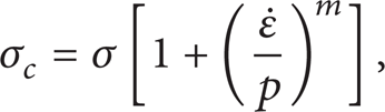
The sheet-forming tool used for the conventional operation consists of a punch, blank holder, and V-shaped die, mounted in a hydraulic press. A schematic of the tool is shown in Figure 1. To investigate the inertial effect on the formability, the punch speed was increased by setting the termination time to 10, 5, 1, 0.5, 0.1, and 0.01 s. Numerical simulations were performed to examine the formability differences between the conventional and EMF operations. Specifically, the simulations were used to extract the void volume fraction, stress, strain, and kinetic and internal energy histories from the FE results. Considering the complex nonlinear characteristics of contact and friction algorithms and the high-speed dynamic behavior, LS-DYNA was used in the transient dynamic plastic-deformation analysis. This is an explicit FEM code capable of analyzing the plastic deformation and contact between the V-shaped die and the sheet blank associated with sheet-metal forming. A two-dimensional (2D) plane-strain problem with a horizontal length of 150 mm is assumed in this study to simplify the load application and geometry definition. The V-shaped die, punch, and blank holder were treated as rigid tools and meshed with 4-node quadrilateral elements. The FE meshes for the conventional sheet-metal forming simulation are shown in Figure 2. The sheet blank used in the simulation was made of AL5052 and had a thickness of 0.7 mm. This aluminum alloy was chosen because it is used quite extensively in the automotive, appliance, and aerospace industries. The constitutive behavior of the AL5052 sheet is described by (1), obtained on the MTS Landmark-370 tensile-testing machine:

where σ is the true stress and ε is the true strain. In the quasi-static deformation phase, the strain-rate sensitivity is ignored, whereas in the high-speed EMF phase, the quasi-static data are scaled to adapt to the high-strain-rate conditions using the Cowper-Symonds constitutive model [11]:
where σ
c
is adjusted flow stress. The
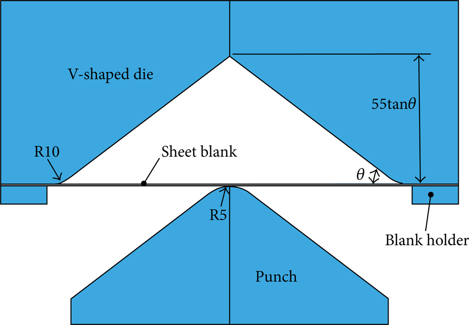
Schematic view of conventional sheet forming into a V-shaped die.

Finite-element mesh for conventional sheet-forming simulation.
2.2. Gurson-Tvergaard-Needleman Material Model
The evolution of ductile damage inside ductile materials can be classified into three phases: void nucleation, void growth, and void coalescence with subsequent crack growth. Usually, these processes can occur sequentially. Many investigations have been conducted to characterize the behaviors of ductile materials. Rice and Tracey [14] studied the enlargement of a single void due to plastic strain in a medium subjected to a uniform remote strain field. To model the plastic flow and failure of ductile materials, Gurson [15] proposed an approximate yield criterion for porous materials that considers the effects of hydrostatic stress, whereas classical plasticity assumes that yielding is independent of the hydrostatic stress. This yield criterion can describe the local necking and failure of ductile materials due to void growth and also illustrates macroscopically the occurrence and growth of damage inside the material without setting a specific void. In addition, the material matrix first is assumed to be isotropic elastic/perfectly plastic and to obey the von Mises yield function. Tvergaard modified the original Gurson model by introducing three material parameters (q1, q2, and q3) for the void volume fraction and pressure terms [16, 17]. Moreover, Tvergaard and Needleman attempted to consider void coalescence by replacing the specific void volume fraction, f, with the effective void volume fraction f* [18]. Now, the yield function of the GTN model can be described as follows:

where σ V , σ Y , and σ H are the von Mises equivalent stress, the yield stress of the matrix material, and the hydrostatic stress, respectively. The effective void volume fraction f* = f*(f) is defined as

In the above relationship, f
c
is the critical value of the void volume fraction, f
F
is the specified void volume based on the macroscopic fracture, and f
u
* is the ultimate value of f* at the ductile fracture. The void volume rate
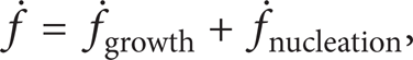
with
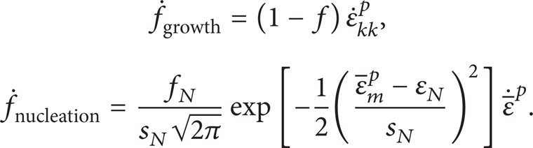
The normal distribution of the nucleation strain has a mean value ε
N
and standard deviation s
N
. f
N
is the volume fraction of the nucleated voids.
According to the yield function given by (3), nine parameters must be identified in the GTN model. In particular, f c , f F , and f0 are significant parameters because they are very closely related to the nucleation and coalescence of the voids inside the material. The initial void volume fraction f0 is determined according to factors of the manufacturing condition, surface defects, and chemical composition [20]. For typical metals, the ranges of the parameters reported in the literature are q1 = 1.0–1.5, q2 = 1.0, and q3 = q12 = 1.0–2.25 [16]. He et al. [21] adopted the modified GTN model to identify the necking initiation area of an AL5052 sheet and determine the parameters of the GTN model using an in situ tensile test. These parameters are listed in Table 1 and were used in this study.
Damage parameters used in GTN material model.

3. EMF Process
3.1. EMF with a V-Shaped Die
The EMF system consists of a low-inductance electrical circuit with large capacitance and high-speed switches for delivering a high-frequency current pulse to a working coil. The procedure for the EMF process with a V-shaped die is shown schematically in Figure 3. The coil (1) is embedded and mounted inside an insulation block (2), which is press-fit into a steel ring (3). The insulation block serves the following dual purpose: it acts as a bandage for the coil, preventing its expansion, and acts as a flat lower binder for the blank (4) that is being formed into the die. The V-shaped die (5) used for the simulation has a height of 55 tanθ mm and an entry radius of 10 mm, which also serves as an upper binder for the bulging process. Here, θ is the side angle of the die. The die has several holes for inserting bolts to attach the forming coil. The flat coil for these simulations is made from square-cross-section copper with a width and height of 5 mm each. The forming coil is based on an eight-turn flat spiral with an outer diameter of 110 mm. The die was clamped onto the working coil using long bolts (6) after positioning the sheet blank on the working coil.

Schematic view of electromagnetic forming apparatus with a V-shaped die.
3.2. Electromagnetic-Structural Coupling Simulation
To predict the deformation behavior and investigate damage evolution and failure in the EMF process, an electromagnetic-structural coupling simulation was performed using the FEM. First, an electromagnetic field analysis was performed using ANSYS/Emag, and then, the electromagnetic force results were transferred as input load to the explicit FEM code, LS-DYNA, to analyze the transient dynamic plastic deformation of the sheet material. In addition, the electric circuit was coupled to an FEM, and a current was applied to the FEs of the working coil. The electromagnetic model consisted of a far-field air region, a workpiece, a forming coil, and an unbounded air region, as illustrated in Figure 4. The geometry was assumed to be a 2D plane, and half of the full model was considered for the simplification, owing to the geometric symmetry of the model. The FE meshes for the electromagnetic and mechanical models are shown in Figure 5. Most regions were meshed using the mapped meshing method with the PLANE53 element, a 2D eight-node planar element for the electromagnetic model in ANSYS. In total, 3,166 elements and 9,587 nodes were used in the electromagnetic model, as shown in Figure 5(a); these were compatible with the 778 elements and 925 nodes of the 2D plane-strain element used in the mechanical model, as shown in Figure 5(b). Although the magnetic field is unbounded, the modeling region was limited by the computation capability and efficiency. In the electromagnetic model, the dimension of the entire analysis region was 2.5 times the width of the sheet, and a specific element, INFIN110 (a 2D eight-node infinite solid element of the electromagnetic model), was employed to represent the open boundary of a 2D unbounded field problem. Finer meshes were utilized to describe the sheet blank, to take the skin effect into account and obtain more accurate results.
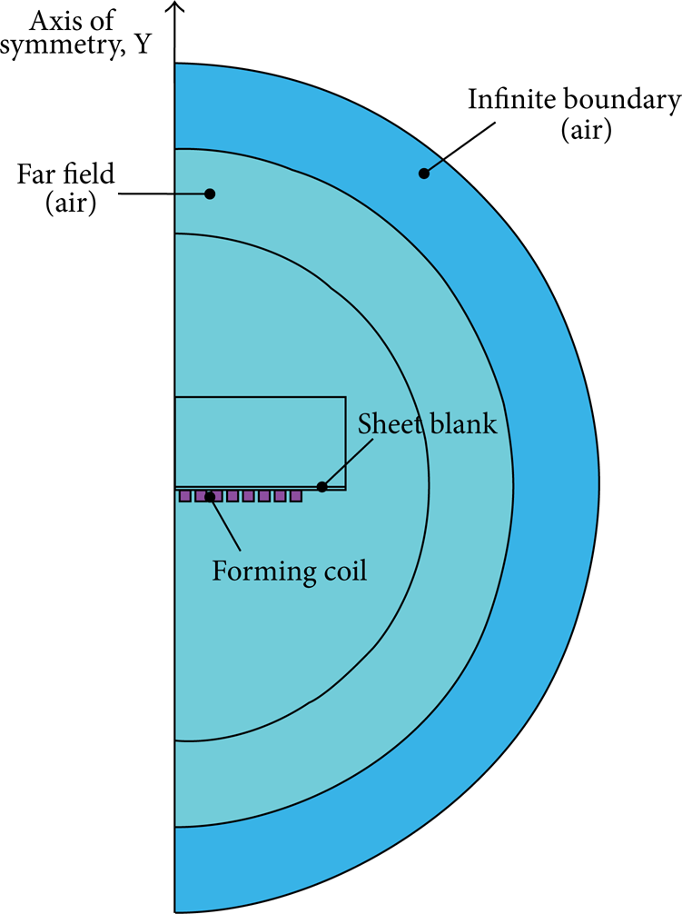
Geometric model for an electromagnetic field analysis using ANSYS/Emag.

Finite-element mesh for (a) electromagnetic model and (b) mechanical model.
The main load in the electromagnetic field analysis is the current flowing in the forming coil. To find the current load generated by the EMF apparatus, the discharge current from the capacitor bank should be modeled by coupling the forming coil to the equivalent electric circuit of the equipment, where the continuity of the current flowing from the circuit to the coil and the equality of the potential drop across the coil are enforced. Initially, all of the electric and magnetic fields can be considered as equal to 0 everywhere in the massive conductor and free space. In ANSYS, coupling involves the degrees of freedom (DOF) CURR (current) and the electromotive force drop (EMFD), which are coupled across the electric circuit to the electromagnetic domain. DOF CURR represents the total current flowing in the massive conductor and EMFD refers to the potential drop across the ends of the conductor. In general, a typical setup for EMF corresponds to an RLC circuit, which consists of a capacitor C, an inductance L i , and a resistor R i . Hence, the CIRCU124 element of ANSYS was used in the construction of the RLC circuit, which considers the coupled electromagnetic-circuit field interaction. In addition, PLANE53, with the DOF of the magnetic vector potential in the Z-direction (AZ), was adapted to the electromagnetic domain of the workpiece and the surrounding air. In particular, PLANE53 elements with characteristics of the circuit-coupled massive conductor and the DOF of the AZ, CURR, and EMFD specified were employed to model the forming coil. The total capacitance (C = 500 μF), equivalent inductance (L i = 5.0 μH), and total resistance of the discharge circuit (R i = 0.01 Ω) were assigned as the physical properties of the electric circuit element CIRCU124. In addition, the capacitor voltage at the beginning of the process was imposed as an initial condition on the CIRCU124 element. The electrical, magnetic, and structural material properties used in the simulation are summarized in Table 2.
Electric, magnetic, and structural material properties used in the simulation.

LS-DYNA was used for the structural coupling numerical modeling in the conventional forming simulation. The Lorentz forces from the electromagnetic field analysis can be stored simply as input loads to the structural model by setting a user-defined subroutine based on the ANSYS Parametric Design Language (APDL). Using the user subroutine, all necessary data, such as the finite-element model of the sheet blank as well as the die, contact conditions, material properties, boundary conditions, and Lorentz forces, can be written to a keyword file as an LS-DYNA input file. For the sequential electromagnetic-structural coupling simulation, the mechanical model and its mesh division were duplicated from the electromagnetic model. The PLANE53 element in the electromagnetic model was replaced with the 2D plane-strain element for the sheet blank in the structural model, and all of the elements in the air region were set to null. In a similar manner, the V-shaped die and binder were treated as rigid tools and the Cowper-Symonds constitutive model was used to model the sheet blank to take the strain-rate sensitivity into account.
3.3. Results of Electromagnetic Field Analysis
When the capacitors are charged and switched across the forming coil through the discharge circuit, a charging current I(t) flows rapidly through the coil. Figure 6 shows the variation in the current density in the coil and the sheet blank when a capacitor voltage of 25 kV is applied. The total simulation time was 500 μs and one time step was 2 μs. When current flows through the coil, a transient magnetic field is generated that fills the space closely surrounding the coil. This magnetic field, in turn, generates a time-varying current in the conductive workpiece, which generates a magnetic field that opposes the field of the coil. According to Faraday's law of electromagnetic induction, the current in the workpiece (denoted as on sheet in Figure 6) is opposite that of the coil. To determine the strength of the magnetic flux developed by the current induced in the workpiece, the magnetic flux densities along the horizontal direction at three different locations—the center, at a 1/4 distance from the edge, and almost near the edge of the workpiece—were compared, as shown in Figure 7. Based on the simulation results for the three locations, the maximum value for the magnetic flux density was found to be 4.12 T at 72 μs at location II. However, it does not cause much of a difference over the sheet blank. The two magnetic fields between the coil and the workpiece repel each other, generating a body force called the Lorentz force; this force repels the workpiece from the coil. The time variation of these Lorentz forces in the vertical direction caused by the interaction of the magnetic fields is illustrated in Figure 8. The maximum value of the Lorentz force was 2431.33 N at 72 μs at location II, whereas at 74 μs, it was 2057 N at location I and 1652.97 N at location III. The Lorentz forces acting on the sheet decayed gradually with processing time owing to the resistance of the discharge circuit. These Lorentz forces obtained from the electromagnetic field analysis were used as the structural loads that were applied to the sheet blank during the plastic-deformation analysis.

Time variation of current density on the coil and the sheet blank.
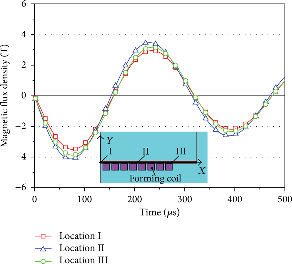
Time variation of magnetic flux density along the X-direction.

Time variation of Lorentz forces along the Y-direction.
4. Comparison of Formability between Conventional and EMF Processes
4.1. Formability
Figure 9 shows the predicted void volume fraction history obtained from the transient dynamic plastic deformation of the sheet using the conventional and EMF operations. As mentioned previously, the punch speeds were increased by setting the termination time to 10, 5, 1, 0.5, 0.1, and 0.01 s, and the corresponding results are listed in Table 3. To consider the inertial effects accurately, no time scale and no mass scale were employed in the simulation. Thus, the total CPU time is dramatically increased with decreasing punch speed. For the computational effort, 6 3.47 GHz Intel Core i7 CPUs were utilized. In Figure 9, “T” denotes the termination time to complete the forming operation. The normalized time represents each time step divided by the terminal time in each case. We found that the predicted void volume fractions met the 0.04854 failure criteria, given as f F in (4), for conventional forming, regardless of the termination time. The element considered for calculating the void volume fraction was the point at which the onset of fracture during deformation was expected for the conventional forming operation, as shown in Figure 10. Moreover, the starting time of the failure occurrence accelerated with decreasing punch speed, whereas increasing speed enhances the formability owing to delaying of the onset of failure. The increases in formability predicted in the EMF have been attributed to constitutive and inertial effects. The constitutive effects are introduced by the so-called high-strain-rate behavior of materials, whereas the inertial effects include those caused by the velocity difference within the sheet blank being formed, which delay the onset of necking during the deformation.
Maximum height with respect to punch speed.


Comparison of void volume fraction at fracture position.
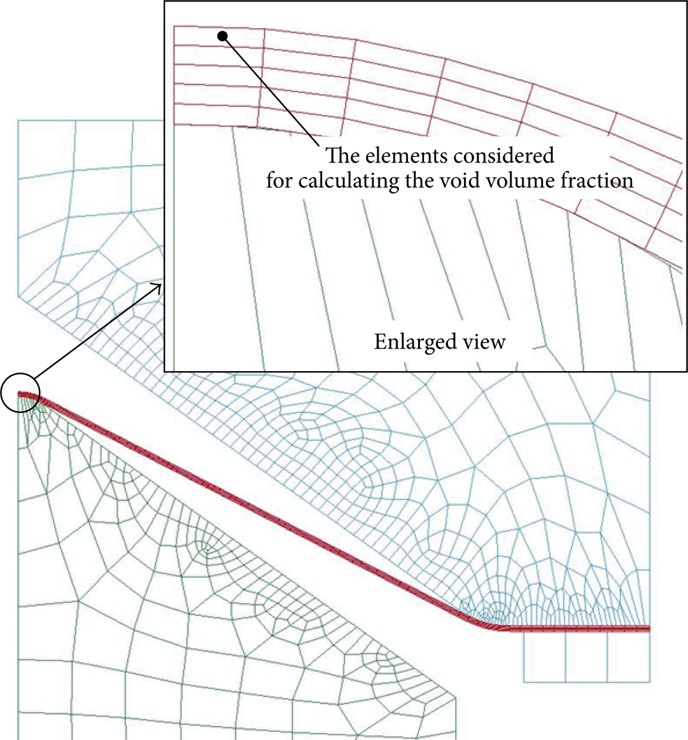
The element at the onset of fracture during deformation.
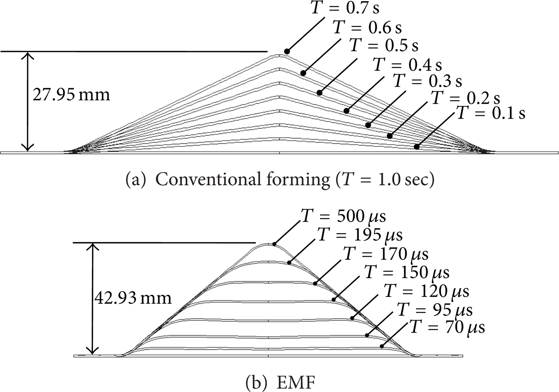
In Figure 11, the displacement at the center of the sheet blank as the vertical height is plotted as a function of normalized time. Because the deformation behaviors of the sheet are almost the same for conventional forming, the results from the case of T = 1 s are compared in the graph. Using the EMF, the blank can be formed completely into the die, whereas using the conventional forming, the bursting failure is predicted at 0.0089 s for T = 0.01 s, 0.088 s for T = 0.1 s, 0.39 s for T = 0.5 s, 0.74 s for T = 1 s, 3.4 s for T = 5 s, and 6.8 s for T = 10 s, as listed in Table 3. For the EMF with complete sheet deformation, the maximum value of the vertical height is expected to be 42.93 mm, but using the conventional forming operation, the maximum value reaches only 25.69 mm until failure for the case of T = 10 s. Because the general stamping operation may take about 1 s of the cycle time, the conventional forming into the given V-shaped die is expected to result in failure of the sheet. In Figure 12, the deformed shapes of the sheet forming into the V-shaped die are compared and they show that the sheet blanks apparently have different deformation histories. For the case of the EMF in Figure 12(b), the sheet progressively rolls up against the die surface; the material contacts the die nonuniformly, leading to a circular line contact that moves upward as the sheet bulges. However, for the conventional forming shown in Figure 12(a), the sheet gradually deforms following the punch and the material is in contact with just the punch-tip surface; it does not interact with the die. Therefore, severe deformation and excessive strain occur on the top surface of the sheet at the center location and lead to failure during the conventional forming operation. It must be noted that the interaction between the tool and the sheet makes the EMF process significantly different from the conventional sheet-forming operation. With conventional forming, most of the damage in the sheet occurs in the apex area, where substantial thinning occurs prior to the final fracture. Figure 13(a) shows that the maximum value of the void volume fraction is 0.031 at the apex of the deformed sheet in the case of T = 1 s. However, no thinning and no fracture are observed in the case of the EMF, as shown in Figure 13(b). For the EMF process, the maximum void volume fraction appears on the sidewall of the deformed part; the maximum value of 0.0186 is much smaller than the failure criteria value.
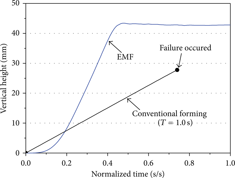
Comparison of vertical height at the center of the sheet.
Comparison of deformed shape of the sheet until fracture.

Comparison of void volume fraction distribution.
The sheet was formed successfully into the V-shaped die only using the EMF process; the conventional stamping operation resulted in failure. Consequently, neck retardation because of the inertial effect and damage suppression due to the tool-sheet interaction may be the main factors contributing to the increased formability in the EMF process compared to the conventional forming operation.
4.2. Effect of Stress, Strain, and Energy History
To better understand the differences in the deformation process with conventional forming and EMF, we examined the detailed stress, strain, and energy histories for the element located at the top of the sheet in the area of failure for conventional forming. All stress and strain components are described in the element coordinate system, where the X-axis represents the length direction and the Y-axis represents the through-thickness direction of the sheet. Figures 14 and 15 show stress histories in the X- and Y-directions, respectively. Because the noise in the stress data was due to the explicit nature of the code used, the results were not filtered to avoid any loss of detail. As can be seen, the stress states are significantly different between the conventional forming and the EMF process. For the conventional forming process, the X-direction stress is consistent with the sheet undergoing uniaxial stretching and gradually increasing owing to the tension imposed by the bending. In addition, at high strain rates, the material exhibits an increase in flow stress and ductility. However, for the case of the EMF, the stress in the X-direction increases owing to the tension imposed by bending; then, as the sheet comes into contact with the die (around a normalized time of 0.45), the stresses decrease dramatically because of the straightening of the sheet. The fluctuations are attributed to the reversed bending that occurs during deformation. Substantial through-thickness stresses are observed to occur at the time of impact, as shown in Figure 15. This large and localized application of through-thickness stress may play an important role in enhancing formability because it changes the stress state and suppresses damage in the region of the deformed sheet that comes into contact with the die. The hydrostatic pressure in the region considered is presented in Figure 16. The hydrostatic pressure history is examined for the elements in question because of the contribution of this pressure to the damage evolution. Once voids nucleate, they must grow for the material to fail eventually. The rate of growth depends on the magnitude of the hydrostatic pressure. In general, the most favorable stress state for void growth is the large negative hydrostatic pressure (hydrostatic stress) produced when the principal stresses are all positive. After the normalized time of around 0.5, higher negative hydrostatic pressures are predicted to occur during conventional forming than those produced during the EMF, which leads to high porosity values on the sheet. Figure 17 compares the predicted effective plastic strain histories between the conventional and EMF processes. The trends in the plastic strain variation are nearly similar to the trend of the predicted void volume fraction that it increases sharply and exceeds the failure criteria. This implies that the product will fail when the conventional stamping operation is used.

Comparison of X-direction stress variation.
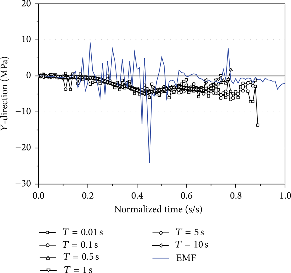
Comparison of Y-direction stress variation.
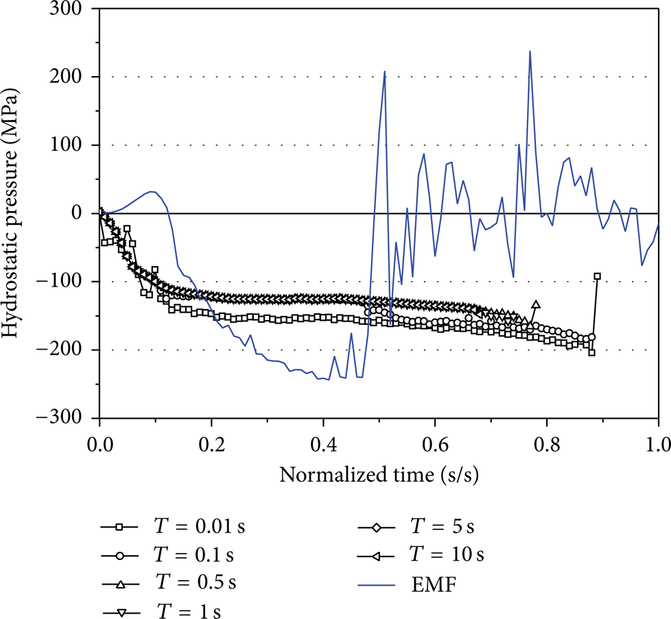
Comparison of hydrostatic pressure variation.
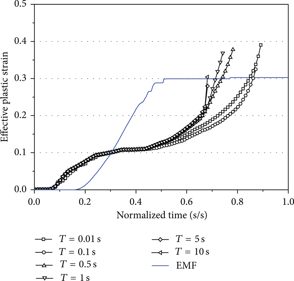
Comparison of effective plastic strain variation.
In Figures 18 and 19, the predicted kinetic energy and internal energy stored in the sheet blank using the conventional forming operation are compared to those using the EMF process. Although the kinetic energy increases as the punch speed increases in conventional forming, its value is extremely small when compared to that in the EMF process; thus, in the conventional forming operation, the kinetic energy can be ignored. Meanwhile, early in the EMF process, the kinetic energy rapidly increases and then dramatically decreases when the sheet comes into contact with the die. The presence of these high kinetic energies produces high strain-rate constitutive and inertial effects, which may be responsible for the increased formability using EMF.

Comparison of kinetic energy variation.

Comparison of internal energy variation.
5. Conclusions
EMF is an impulse or high-speed forming technology that uses pulsed magnetic fields to deform a sheet-metal workpiece without mechanical contact and without a working medium. Despite the fact that an increase in the formability of the EMF in a V-shaped die or in a conical die has been proven, it is not completely clear why formability is enhanced in the EMF process compared to the conventional stamping operation. In this study, we performed comparative and numerical studies of the conventional stamping operation and the EMF process to form a V-shaped die. In the numerical simulation, an electromagnetic field analysis was performed using ANSYS/Emag. The electromagnetic force results were transferred as input loads to the explicit FEM code, LS-DYNA, to analyze the transient dynamic plastic deformation of the sheet material. Finally, using the Gurson-Tvergaard-Needleman plasticity material model, we investigated the effect of process speed on the damage evolution and failure in the conventional forming and the EMF process. The main conclusions of this work are summarized as follows.
The sheet could be formed successfully into the V-shaped die only when the EMF was used; forming with the conventional forming operation resulted in failure.
The impact of the sheet with the die generates a complex stress state during the EMF process and this makes the associated deformation behavior fundamentally different from traditional manufacturing processes such as stamping. Therefore, damage suppression due to the tool-sheet interaction is probably the main factor contributing to the increased formability in the EMF process compared to the conventional forming operation.
A high level of kinetic energy provides high-strain-rate constitutive effects and the inertial effect, which delay the onset of necking and are responsible for increased formability using EMF.
Conflict of Interests
The authors declare that there is no conflict of interests regarding the publication of this paper.
Footnotes
Acknowledgments
This work was supported by the National Research Foundation of Korea (NRF) Grant funded by the Korea Government (MSIP) through the Engineering Research Center (no. 2012R1A5A1048294) and the Human Resource Training Project for Regional Innovation (no. 2012H1B8A2026095).