
Abstract
The composite structure-similar flutter model (ComSSM) not only shows higher structural efficiency but also provides convenience for the purpose of fabrication in the aerodynamic flutter model. The manufacturing process of ComSSM is different from conventional composites structures. The geometry parameters and nongeometry parameters of ComSSM need to be controlled cooperatively and precisely to obtain higher product quality. A method of precise manufacturing is developed based on the error calibration of nongeometry parameters. The accuracy of structural performance of ComSSM is ensured by reducing the manufacturing stiffness, controlling the error of mechanical performance, and calibrating the error of modal frequency.
1. Introduction
Transonic flutter wind-tunnel test is an important way to investigate the characteristics of transonic flutter. The flutter model plays an important role in wind-tunnel tests [1]. The model of experiment similarity theory requires that the scaled model must be similar to the original structure, such as the wing. This means that the surface contour, stiffness, and mass of the scaled model need to have a certain scaling relation with the wing. Otherwise, it is difficult to obtain a useful flutter boundary in the wind-tunnel test.
There are several types of scaled models that are developed for flutter wind-tunnel tests. The metallic (mainly aluminum or steel) skeleton model is a typical aeroelastic scaled model. It is composed of metallic skeleton, closed-cell foam, and skin. The metallic skeleton is the major supporting structure, which provides of the major bending stiffness and torsional rigidity. The skin structure only transmits the external loadings to the metallic skeleton and bears little bending and torsional deformation [2]. Compared with the wing-box structure, the structural efficiency of metallic skeleton model is relatively lower. In order to keep the similarity of mass to the original wing, the metallic skeleton model needs to add some additional balance weights to adjust the position of center of gravity, which makes the total weight exceeding the design objective. Such an overweight will affect the result of wind-tunnel test especially in subsonic state [1, 2]. Variable stiffness spar scaled model is another model type in wind-tunnel tests [3]. It adopts a variable stiffness metallic spar to simulate the bending stiffness and torsional rigidity. The variable stiffness metallic spar is easier to design compared to the metallic skeleton model. However, alike the metallic skeleton model, the variable stiffness spar model also faces the problem of overweight. Recently, a rapid prototyping (RP) based aeroelastic model was developed [4, 5]. This is a kind of the metallic skeleton model based on the constructing features. The only difference from the metallic skeleton model is that the metallic skeleton model is mainly fabricated by numerical control machining and RP method is mainly fabricated by the rapid prototyping (also known as layered manufacturing) process. For wind-tunnel test, the overweight problem is still a challenge for engineering applications.
Composites structural-similar model (ComSSM), as shown in Figure 1, is an advanced scaled model which was first presented by TsAGI of Russia [6]. In order to improve the similarity of aerodynamic to the original aerostructure, ComSSM takes a partly structure-similar to the original structure. Namely, ComSSM is composed of composites beams, ribs, and skins which are close to the structure of wing box (see Figure 3). All of the beams, ribs, and skins were made of fiber reinforced plastic (FRP) and designed to provide similar rigidity characteristics compared to the original structure. Such a structure can increase the material utilization rate and reduce the structure weight. This process can easily realize the similarity of stiffness and mass between scaled model and original aerostructure.
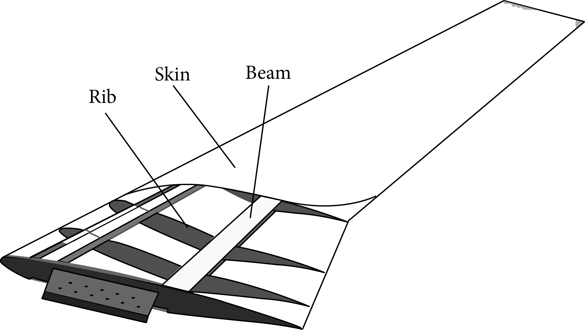
The structure of aircraft wing ComSSM.
According to the demand of transonic flutter wind-tunnel test, the manufacturing of ComSSM needs to guarantee the dynamic stiffness (generally using modal frequencies to measure it) of ComSSM, which needs to be in a given error range. Such a demand of manufacturing is different with conventional composite structures. The manufacture of common complex composite structures is usually dedicated to improving the process to enhance the static stiffness and dynamic stiffness. So, the traditional manufacturing method of composite structure is insufficient for ComSSM manufacturing.
There are too many factors that affect the accuracy of ComSSM manufacturing. For example, the natural frequencies are one of the most important objectives for ComSSM manufacturing. However, some studies show that the dispersion in composite material properties could be a big problem for natural frequencies of the composite structures [7, 8]. Sarangapani and Ganguli have also shown that the effects of uncertainty in composite material couplings can be quite significant [9]. In addition, due to the inability of FEM to capture all the dispersion in geometry, boundary condition, and so forth, the analysis errors also have an important influence on the manufacture precision except the material property dispersion. The finite element model updating is the typical approach to improve the analysis results, such as that discussed in Ren and Chen [10], Marwala and Sibisi [11], and Mottershead et al. [12].
In this paper, a precise manufacturing method based on the controlling of nongeometry parameters is presented to solve the manufacturing problem of ComSSM. The procedure of this method is to control the dynamic stiffness of ComSSM in a specific range that is close to the object firstly, and then to measure the error of dynamic stiffness of ComSSM to reverse an error correcting scheme according to the result of measuring. Finally, the anisotropy of composite is utilized to adjust the local stiffness characters to achieve the precise manufacturing of ComSSM.
2. Error Analysis and Manufacturing Process
ComSSM is a complex composite structure and many manufacturing factors will affect its modal frequency errors, which generally includes four aspects. First, the engineering assumptions errors in the design will make the simulating result different from the actual structure. Second, the material properties of those close-cell foam and FRP, such as elasticity modulus, and density, and so forth, are not stable enough and the dispersing of structure materials can make the modal frequency of ComSSM away from the design objective. Third, to ensure that ComSSM surface is smooth, beams, ribs and foam must be bonded to the skins in the assembling, which means that there will be an epoxy resin layer under the skins. As the surface of foam will absorb uncertain resin, it is difficult to predict the amount of stiffness that epoxy resin would provide. That will produce additional stiffness to ComSSM and result in producing errors. Finally, the geometry errors produced in FRP structure forming and assembling also can affect the precision of the modal frequency.
Without efficient control manufacturing, the modal frequency errors of ComSSM have higher opportunity to exceed design tolerance. Sometimes the error rate will reach up to 20%.
The manufacturing process of ComSSM is a typical functionally complex structure manufacturing process. Considering the characteristics of composites structural fabrication, method of nongeometry parameters precise manufacturing based on modal frequency error calibration is developed in this paper.
3. Method of Precise Manufacturing
The forming process of composites is a typical material-increase manufacturing process, so the stiffness of composite structure can be easily increased by adding in new composite layers. As the precise mechanical removing process of a single layer of composite fiber after curing is difficult to achieve, the stiffness of composite structure has difficulties to be decreased. With the design-ability of composites, specific lay-up design of different thickness and orientation can provide the corresponding calibration of structural parameters. So the modal frequency error of the aircraft wing ComSSM can be calibrated with negative stiffness deviation control. The standard procedure of nongeometry parameters precise manufacturing is provided in Figure 2.
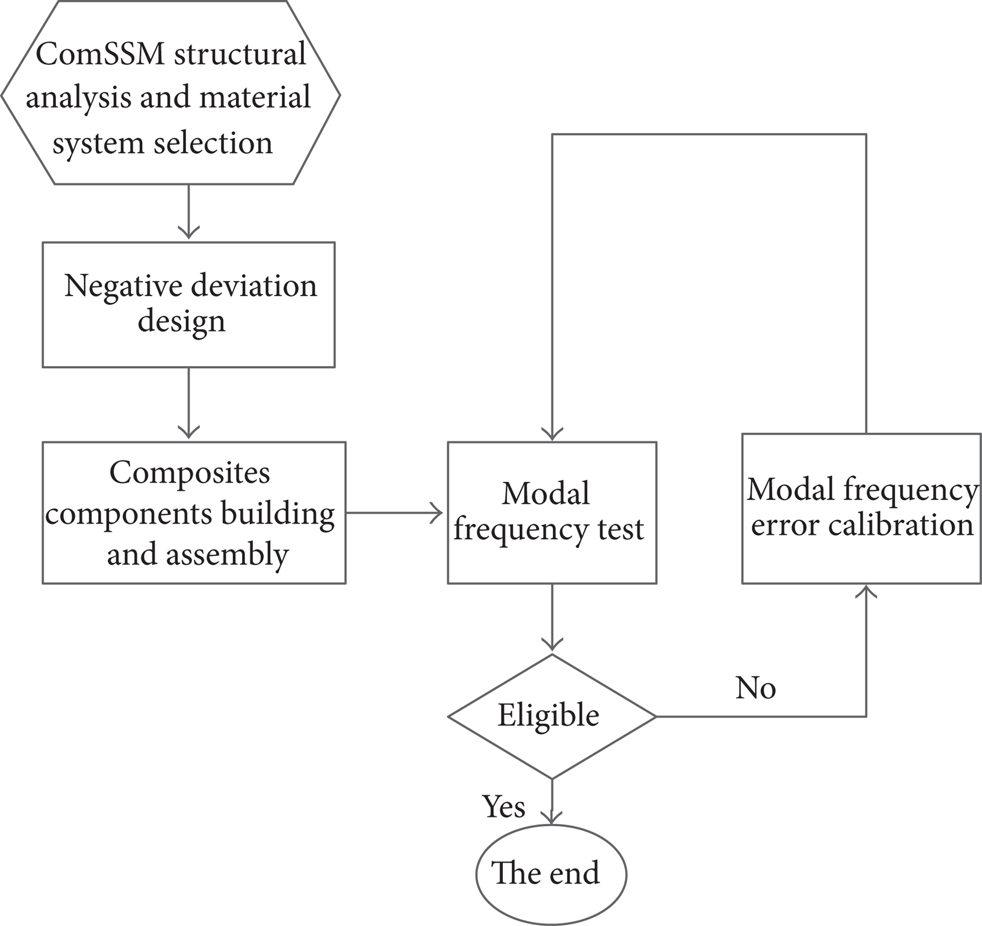
The procedure of nongeometry parameters precise manufacturing.

The structure of the typical wing box.
3.1. Negative Deviation Control
The dispersity in composite material properties, also known as material uncertainty, has significant influence on ComSSM stiffness. This kind of influence can cause stiffness errors of the ComSSM, which would appear as deviation from the true value of ComSSM stiffness in positive or negative direction. And additional stiffness added by excessive epoxy bonding can lead to ComSSM stiffness positive deviation. Comprehensively, the stiffness of ComSSM generally exceeds the upper limit of allowance. To build a ComSSM with high stiffness parameters accuracy, the concept of negative deviation control taken from manufacturing experience is added into the accuracy design of ComSSM. A precalibration model with lower stiffness is built ahead, so the stiffness of this model is set with negative deviation from the true value. With lower stiffness parameters, the effect of additional stiffness is neutralized. The stiffness of ComSSM would not exceed the upper limit of allowance and there also existed allowable margin for stiffness parameters calibration. The negative error of stiffness caused by dispersion in material properties could be neutralized after error calibration process. The value of negative deviation could be obtained after stiffness parameters test, and it could be set to 5∼10%.
4. Qualification Test and Modal Frequency Error Calibration
According to the vibration theory, the undamped vibration equation of the ComSSM is presented as follows:
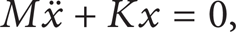
where M is the mass matrix of the structure, K is stiffness matrix of the structure, and x is the displacement vector of the model. Based on the modal coordinate transforming, (1) can be written as follows:

where φ i is the natural mode and ω i is the natural frequency. So the stiffness and mass distribution can be tested by modal frequency tests.
The performance of inner structures is obtained by the modal frequency test of composite skeleton in advance, and it is the precondition of qualification test for composite skins. The skins components need to be bonded with beams and ribs momentarily for qualification test. alpha-cyano ethyl acrylate is used for structure bonding. alpha-cyano ethyl acrylate can be removed by heating, so skins, beams, and ribs can be safely separated after qualification test.
4.1. Modal Frequency Error Calibration
Considering the advanced designability and anisotropic property of the composite materials, the bending-twisting coupling effect can be used for the error calibration of ComSSM nongeometry parameters. Based on the theory of the composite laminate, the stiffness equation is presented [13] as follows:


where N is the internal force and M is the internal moment. ε0 is the strain of neutral surface, and k is the curvature of neutral surface. A, B, and D are the matrices of the tension stiffness, coupling stiffness, and bending stiffness, respectively.
Because the stiffness error consists of errors of both bending stiffness and torsional stiffness, the error calibration should modify these two parts at different levels. According to (4), the coupling stiffness factors can be obtained by specific composites lay-up design [14, 15]. Adding composite layers of different thickness and different lay-up orientations on different positions of the skin component would satisfy lay-up design for error calibration. And the modal frequency error can be calibrated [16].
4.2. Optimization Formulations of Error Calibration
The skin component is separated into many parts for optimization consideration, and these parts indicate positions for composites lay-up design. In this optimization, optimization variables are the thickness and the orientation of composites layers for every separated part added to the inner surface of skin components. The objective value is the modal frequency. The optimization formulation can be written as follows:
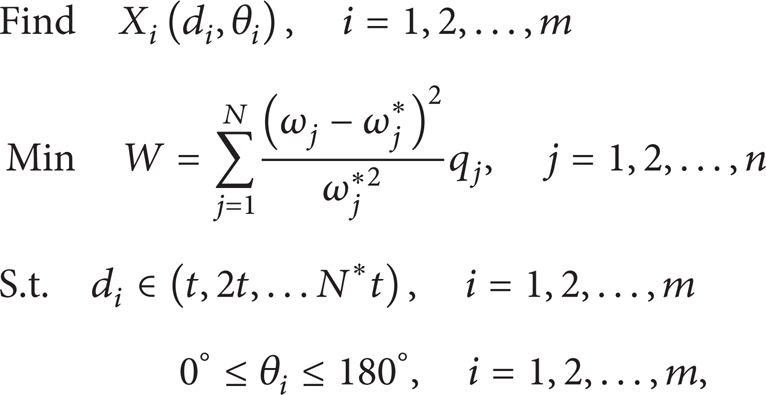
where ω j * is the target modal frequency and ω j is the current modal frequency. q j is the weighting coefficient and d i and θ i indicate the thickness and the orientation angle of the adding composite layers, respectively. J and i are set to be the number of the order of separated parts. Because the thickness of single layer is constant value, d i is discrete.
The optimization problem is solved by nonlinear programming by quadratic Lagrangian (NLPQL) algorithm to optimize the example of error calibration [17, 18].
4.3. Optimization Procedure
During the optimization process, the quantity of separated parts is greater than the quantity of general optimization variables. Furthermore, the optimization variable consists of continuous variables and discrete variables. Therefore the optimization example is established to solve the problem with mixed variables. The optimization steps are summarized as follows.
Step 1. First, a proper material system is selected for error calibration. Then FEM of wing box is built. This FEM is partitioned. The structural sensitivity analysis is adopted to obtain parts for optimization.
Step 2. Run NLPQL optimization program to get computing result.
Step 3. The optimization results of layer thickness need to be rounded off. And layer orientation design needs extra optimization.
Step 4. The error calibration example is obtained.
5. Results and Discussion
5.1. Finite Element Model
The composite materials used in the wing box were glass fiber reinforced resin with quasi-isotropic stacking, and the layers are layered in a [0°/45°/90°/−45°] s configuration; Table 1 lists the materials properties of the plies.
Material properties of plies.

The finite element (FE) method was used for the modal analysis. The types of element to simulate different components were decided based on the force-transfer type of the structure. Thus the web of beam, the rib, and the skin were discretized by the composite shell elements, while the flange of the beam was simulated by beam elements. The mode and frequency of the 1st order bending vibration, the 2nd order bending vibration, and the 1st order torsional vibration of this wing box are shown in Figure 4.
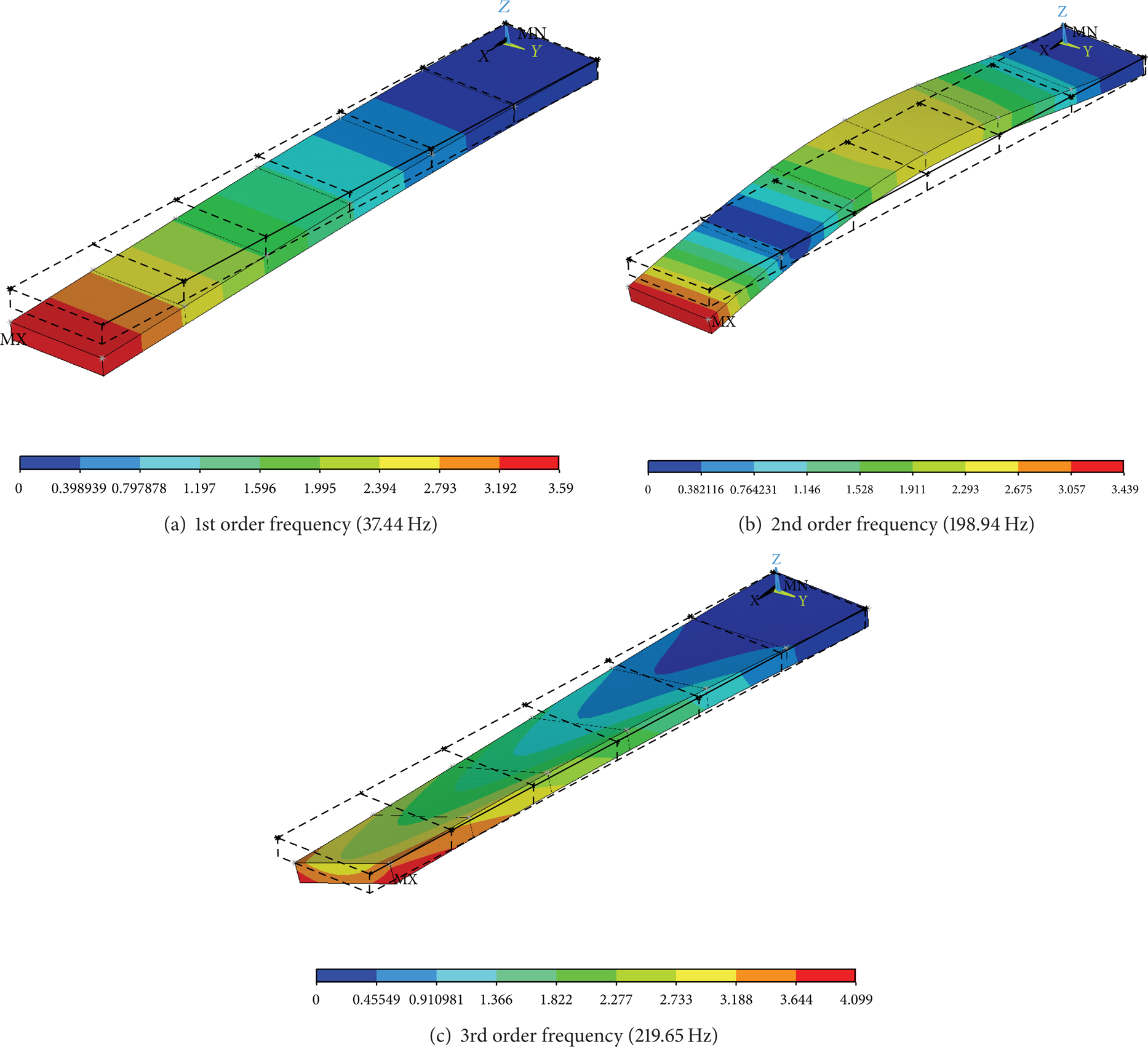
The modal shapes of the initial wing box.
5.2. Composite Structure Fabrication
The wing box was built by the mold manufacturing, the forming of composite components, and the assembling. In the components forming procedure, a low-pressure contact molding process was used. The proportion of the fiber and the resin was chosen to satisfy the requirement of the design. The main forming parameters including temperature and pressure were controlled in the autoclave. During the assembly, the position of components was fixed by the fixture, and the amount of the glue was controlled to reduce the additional stiffness. The cured composite wing box was shown in Figure 5. The nuts were used as balance weights for the weight adjusting.
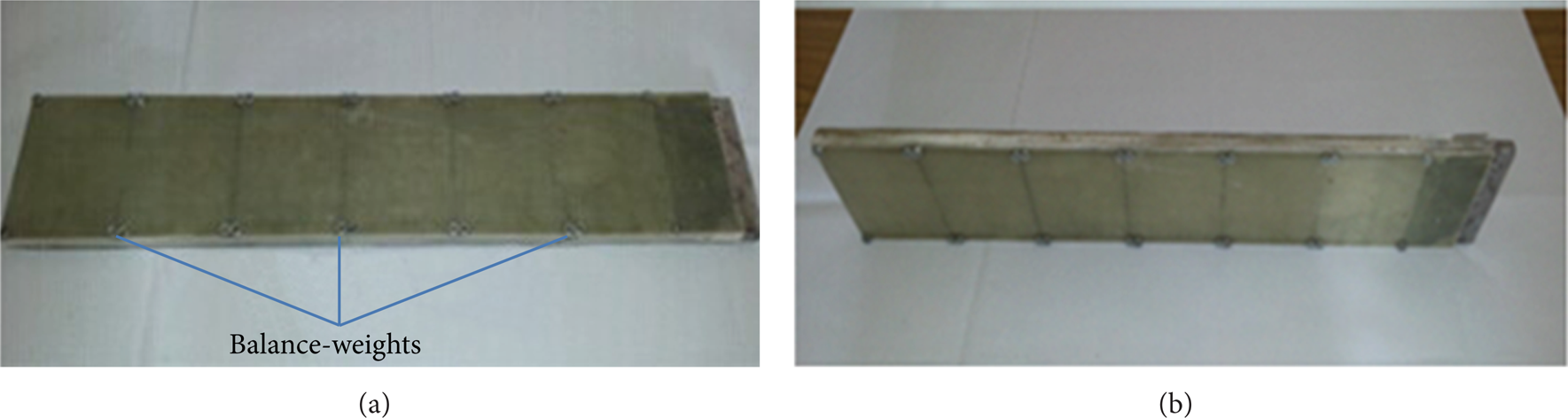
The composite wing box.
Table 2 lists the actual natural frequency that cannot fairly match with the data from the FE analysis because of the material dispersion error. For example, the 1st order natural frequency exceeded the desired one for 5%. The material parameters in the FEA model, which were the main coefficients of the material dispersed error, needed to be calibrated. The optimization method was adopted to calculate the actual material parameters. The relative error of the natural frequency was below 3% after the calibration, as shown in Table 2. The actual material parameters of components were listed in Table 3.
The modal frequency result of the FEA method and the modal test.

The actual material property of the wing box.

5.3. Optimization of Error Calibration Example
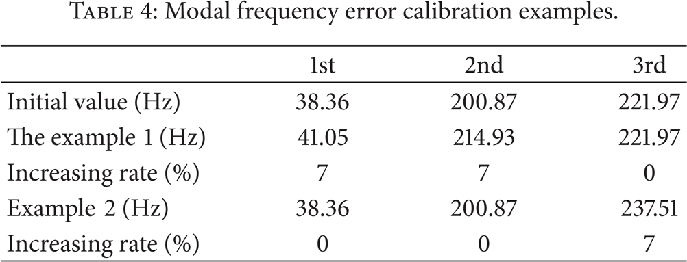
This experiment contained two error calibration examples. The aim of case 1 was to increase the bending frequency while keeping the torsional frequency unchanged. Case 2 was opposite to case 1. The detailed target value was listed in Table 4. The 7% of the increasing rate can satisfy the practical use in the error calibration of the composite flutter model.
Modal frequency error calibration examples.
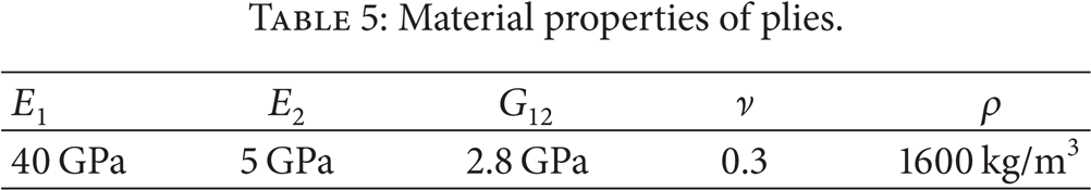
The skins mainly undertake the bending and torsional loading, so the skins are the ideal structure of the error calibration. The skins were separated into 36 regions, as shown in Figure 6. The unidirectional carbon fiber fabric was used as additional materials. The orientation angle of carbon fiber fabric moves limits are put as −90 to 90 in the analysis model [19]. The thickness of one layer was 0.2 mm. The material properties of plies were listed in Table 5.
Material properties of plies.

The partition of the error calibration region.
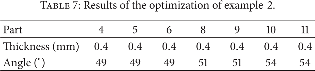
The optimal example, which was based on the sensitivity analysis and the NLPQL method, was adopted to determine the location, the thickness, and the angle of the adding composite layers. The wing box is a symmetric structure, and the quantity of the locations can be halved. The result of the optimization is given in Tables 6 and 7; meanwhile, the additional composite layers in the wing box of the two examples were shown in Figure 7.
Results of the optimization of example 1.

Results of the optimization of example 2.

The adding of composite layers of the wing box.
To guarantee the accuracy of the experiment, the fixation condition and the measuring points of the wing box after the error calibration should be consistent with the initial one. Figure 8 demonstrates the modal test result. The peaks of the frequency response function (FRF) are concentrated, and the mode vibration is distinctive to identify, so the stiffness of the base is proper and the data provided is accurate.

The modal test result after the implementation of two examples.
5.4. Result and Discussion of the Experiment
Compared with the initial modal shapes, the modal shapes after the calibration of the two examples were unchanged, as shown in Figure 9. The result can satisfy the designing requirement. Figure 9 illustrates the comparing relationship of the FRF curves in the same measuring point between the two error calibration examples and the initial one. In example 1, the bending frequencies increase distinctively while the torsional frequency changes slightly. The result of example 2 is opposite, the torsional frequency increases distinctively while the bending frequencies remain unchanged. So the effect of the error calibration is obvious.

Comparison of the FRF curves.
The experimental results of the error calibration are listed in Tables 8 and 9. The increasing rates of the bending frequencies in case 1 and the torsional frequency in case 2 are all greater than 5%. Meanwhile, the increasing rate of the torsional frequency in example 1 and the bending frequencies in case 2 are less than 1%. At the same time, the errors of case 1 and case 2 are all less than 1.5%. The actual result matches the data of the optimization well. Thus, the error calibration method presented in this paper is an effective method to the precise manufacturing of the ComSSM for the wind tunnel tests.
Results of error calibration of example 1.

Results of error calibration of example 2.

With the application of the method, a high aspect ratio wing ComSSM, a stabilator ComSSM, and a full aircraft ComSSM at transonic speeds were manufactured. The main modal frequency parameters such as 1st order bending frequency, 2nd order bending frequency, and 3rd order torsional frequency can be achieved with errors less than 10%. Sometimes, the error can be less than 5%.
6. Conclusions
The fabrication of ComSSM is a kind of functional complex structure manufacturing problem. It requires precise control of geometry parameters and nongeometry parameters. Therefore the fabrication process of ComSSM needs simultaneous controlling of geometry parameters and nongeometry parameters.
This theory of manufacturing can also be applied to manufacture static aeroelastic wind-tunnel test model. Because the static aeroelastic wind-tunnel test model needs more precise geometry parameters, the deformation of composites during curing process still needs to be studied.
Conflict of Interests
The authors declare that there is no conflict of interests regarding the publication of this paper.
Footnotes
Acknowledgments
This work is sponsored by National Natural Science Foundation of China (no. 51275073) and Science Fund for Creative Research Groups (51321004).