
Abstract
Supersonic combustion in two-model scramjet combustors of hydrogen and hydrocarbon fuel was, respectively, simulated using the in-house two-dimensional compressible, turbulent, and reacting flow code. Three kinds of compressibility modifications, namely, the dilatational compressibility, structural compressibility, and shock unsteadiness corrections, were incorporated into the k-ω shear stress transport (SST) model, respectively. In addition, the case that employs all the three corrections simultaneously was also performed to evaluate the coupling effect of these individual corrections. The steady laminar flamelet model was adopted to simulate the interaction between turbulence and chemical kinetics. The calculation results using compressibility modifications are in good agreement with experiments, validating the effectiveness and accuracy of the turbulent modification model. Results show that the dilatational compressibility correction model has good versatility in all conditions. The structural compressibility correction model demonstrates the best correction effect in near wall region but has no significant effect in the central flow field. The correction effect of the shock unsteadiness compressibility correction model is sensitive and proportional to the strength of shock wave. Moreover, the coupling case gives the most remarkable correction effect in most situations, indicating that the overlying effect may improve the prediction accuracy.
1. Introduction
Supersonic combustion in scramjet combustor is an extremely complex phenomenon, involving shock wave, turbulent flow, chemical reactions, heat release, and the coupling effects of the above factors. Accurate predictions of these flow fields depend on the turbulence and combustion models used [1]. The original turbulence models were proposed mainly based on the incompressible flow and therefore the density is constant. However, with an increase of Mach number, compressibility has a considerable influence on the fluid field structure. For example, a remarkable reduction in the growth rates of compressible turbulent free shear layers was observed comparing with the incompressible flow. The widely used two-equation turbulence models such as k-ε model and k-ω model can no longer obtain reasonable results. Therefore, compressibility modifications must be taken into account in compressible turbulence closures.
In general, compressibility modifications may be divided into three groups: dilatational compressibility, structural compressibility [2], and shock unsteadiness modifications [3]. The former one is related to a nonzero mean dilatation or dilatation correlations. During the last decades, quite a few models, such as Sarkar et al. [4, 5] modification, El Baz and Launder [6] modification, Zeman [7, 8] modification, and Krishnamurty and Shyy [9] modifications, have been proposed to address the overprediction of the mixing layer thickness obtained by the turbulence models based on incompressible flows. Due to its simplicity and excellent performance, Sarkar modification has been widely applied in numerical simulations. The latter two modifications are related to the changes of the flow fields’ structure [10]. Moreover, structural compressibility effect is known to play a more influential role in suppression of the growth of TKE [2]. Nevertheless, models dealing with the latter two modifications are rarely reported at present. Heinz [10] modification and Sinha et al. [3, 11] modification were developed to model the structural compressibility effect and shock unsteadiness effect, respectively.
In previous studies, most proposed treatments dealing with the compressibility effects were discussed in the context of the standard k-ε model [2–13], and they were mainly applied in the nonreacting flow field simulations [2–15]. In this work, these modifications are firstly transformed into the k-ω SST formulation and then used in the numerical study of supersonic reacting flow to evaluate their effects on combustion process. Besides, the coupling effect of all the three corrections is also addressed.
2. Governing Equations and Turbulence Closure
2.1. Governing Equations
The two-dimensional Favre-averaged Navier-Stokes equations with k-ω SST turbulence model and the transport equations for mixture fraction and its variance, which are employed in the steady laminar flamelet model (SLF), are expressed in a flux vector form as

where
For the closure of the momentum equation, a two-equation turbulent model, the shear stress transport (SST) k-ω model is employed. SST model, developed by Menter [16, 17], is a combination of k-ε model and k-ω model connected by a switching function. This turbulence model was proposed to keep the better features of both models in the supersonic flows, that is, to retain the robust and accurate formulation of the k-ω model in the near wall region and to take advantage of the insensitive feature based on the freestream values of the k-ε model. The switching function was designed to switch from the k-ω model near the wall surface to the k-ε model in the free shear flow, and the blending takes place in the wake region of the boundary layer. The governing equations of SST model are given as

where k and ω = ε/k (k is the turbulent kinetic energy and ε is the dissipation rate) are the turbulent variables. β*, σ k , σω, and σω2 are model constants; γ is the special heat ratio. μ and μ t denote the molecular dynamic viscosity and turbulent viscosity, respectively. ν t = μ t /ρ is the turbulent kinematic viscosity. F1 is the blending function. P k is the turbulence kinetic energy production term. At the solid wall surface, the turbulent kinetic energy k = 0, and ω = 10(6ν/β1(Δy1)2), where ν denotes the kinematic viscosity and Δy1 is the distance to the next point away from the wall.
The SST model can provide very accurate results for the simulations of separated flows with an adverse pressure gradient. However, the model does not contain any compressibility modifications for high speed flows.
2.2. Dilatational Compressibility Modification
In the present work, Sarkar et al. [4, 5] modification is adopted to model dilatational compressibility effect. Since velocity divergence is nonzero in compressible flows, several new terms need to be modeled, such as the dilatation dissipation ε
d
and the pressure dilatation
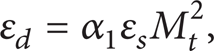
where ε
s
denotes the solenoidal dissipation rate. On the other hand, the term

Note that both the term ε
d
and
It should be pointed out that, in the SST model, the Sarkar modification is made only on the k-ε equations and the k-ω equations are left undisturbed. Since the Sarkar modification is developed based on the standard k-ε model, the first step for the derivation is to transform the k-ε model equations including extra terms for compressibility corrections into k-ω formulation using the relation ε = β*ωk. And then the original k-ω equations and the transformed equations are multiplied by the blending functions F1 and (1 − F1), respectively. Finally by adding the two sets of corresponding equations together, the SST model with Sarkar modification can be obtained as follows:

2.3. Structural Compressibility Modification
As the initially proposed and the most representative model for structural compressibility effect, Heinz [10] modification is employed in this study. Gradient Mach number M g , which is defined as M g = Sl/a [14], is introduced to measure the strength of compressibility in this model, where S denotes the shear rate, l the turbulence length scale, and a the speed of sound. M g grows with the extent of compressibility and M g = 0 indicates an incompressible flow. The constant Cμ in k-ε model is now a function of M g as follows:
It is noted that the value Cμ = 0.07 at M g = 0 is inconsistent with Cμ = 0.09 in standard k-ε model, so herein the computation of Cμ is adjusted as follows to be expected to yield better predictions:

Obviously, the neglect of this reduction in the value of Cμ without compressibility corrections may result in significant errors. For the constant Cμ in k-ε model being just the same parameter as β* in SST model, it is straightforward to incorporate this modification in the standard SST model.
2.4. Shock Unsteadiness Modification
In the k-ε model, the production of TKE is given by

where τ
ij
denotes the shear stress term. In a shock wave, this term is proportional to
In the current work, shock unsteadiness is modeled using Han's modification [18]. By introducing the limiter of turbulent viscosity μ t proposed by C. H. Park and S. O. Park [19], a limiter of the production of TKE can be deduced as

Therefore, the production of TKE should be

2.5. Numerical Methods
In high speed, compressible, and reactive flows, the coupling between turbulence and nonequilibrium chemistry is rather complex. The global chemical kinetic mechanisms that are usually used in finite rate type methods can no longer give a precise description of species distributions. On the other hand, it is a tough task to incorporate detailed mechanisms in finite rate computation due to the stiffness problem in species equations and the high requirement for computing performance. As the turbulence and species transport are decoupled in calculation, the steady laminar flamelet model [20] is well suited for the scramjet flow filed simulation. In this model, it is assumed that the inner structure of the flame would not be destroyed by turbulence; hence the turbulent flame is regarded as a statistical ensemble of one-dimensional laminar diffusion flame structures embedded in the turbulent flow field. Therefore, the parameters such as species mass fractions or temperature can be directly obtained by interpolation from the flamelet libraries which are one-dimensional in mixture fraction space that is generated in advance. So the detailed mechanisms can be conveniently introduced without remarkable increase in the computation cost. For the hydrogen, the reaction mechanism of Maas and Warnatz [21] with 9 species and 19 step reactions is employed. For the ethylene, the mechanism developed by Zambon and Chelliah [22], which consists of 31 species and 128 step reactions, is used.
The traditional flamelet model was developed under the low Mach number assumption, so it is not appropriate to use this model directly in supersonic flow. Here the modification method we chose is proposed by Oevermann [23], in which only the species mass fractions are obtained from the flamelet library and the local temperature is calculated from the solution of the energy equation.
The governing equations are solved by means of a finite volume method based on structured grids. A semi-implicit first order time-marching scheme is well suited to seek for a steady-state solution. A nonoscillatory, containing no free parameters, and dissipative (NND) scheme [24], which has total variation diminishing (TVD) properties, is used here for the discretization of the convective fluxes. NND scheme is suitable for the capture of shock wave in the transonic/supersonic flow. The viscous fluxes and source term are discretized using the second order central difference method.
Besides, viscosity and specific heat of the mixtures have been evaluated using mass-weighted-mixing law. For the individual species in the mixtures, these properties have been evaluated using Sutherland's law and fifth order polynomials in temperature, respectively.
3. Results and Discussion
3.1. Hydrogen-Fueled Supersonic Combustion Simulation
The hydrogen-fueled scramjet combustor model employed here was tested at the German Aerospace Center (DLR) [25]. Figure 1 shows the schematic of the combustor. The combustion chamber is 45 mm × 50 mm at the entrance, with a divergent angle of 3° along the upper wall. Its total length is 300 mm. Besides, a wedge strut is located at the centerline of the combustor. In the experiment, the main stream consists of preheated air expanded through a Laval nozzle and injected at Mach 2.0. The hydrogen is injected parallel to the air through 15 identical holes with a diameter of 1 mm at the base of the wedge with sonic velocity.

Schematic of the hydrogen-fueled combustor.
Based on multiblock grid technique, the computational domain was split into three blocks. Grid refinement has been made near the wall boundary region, the strut region, and the shear layer. The flow conditions of the incoming air stream and the fuel jet are given in Table 1. The static pressure, static temperature, Mach number, and main species mass fractions at inlets are specified. These parameters are set as Dirichlet boundary conditions. For the outlet, the Neumann boundary condition is applied in the calculation. The fixed walls of the combustors are set as a no-slip condition.
Inflow conditions of test case 1.

Before the comparison analysis of different compressibility modifications, the grid independence study is first presented here. In the current work, three different sets of grid have been generated in the numerical simulations, namely, Mesh 1, Mesh 2, and Mesh 3. Mesh 1 consists of 30, 360 cells in all. Mesh 2 and Mesh 3 were obtained from Mesh 1 by successive grid refinement in certain regions, containing 42,290 and 61,664 cells, respectively. Figure 2 demonstrates the velocity distributions along the middle of the channel (y = 25 mm), on the three different grids.

Velocity distributions along y = 25 mm for various grids.
It can be seen that the results on the three different grids only show little difference, and the predictions of Mesh 2 and Mesh 3 are nearly identical with each other. Taking account of the accuracy and computation cost, Mesh 2 was employed in the following study.
For the cold flow without reaction conditions, Figure 3 shows the computation results and experimental data of pressure distributions along the middle of the channel (y = 25 mm). It is noted that the experimental trend is fairly well predicted by the simulation, both qualitatively and quantitatively, validating the effectiveness and accuracy of the numerical model used here.

Simulation results of pressure distributions along the middle of the channel (y = 25 mm).
For the reactive flow with combustion conditions, to assess the effects of the several compressibility modifications mentioned above on reactive flow fields, five cases using different turbulent model combinations are simulated, that is, (i) standard k-ω SST model, (ii) SST model with dilatation compressibility correction, (iii) SST model with structural compressibility correction, (iv) SST model with shock unsteadiness correction, and (v) SST model with all the three corrections. The last case is performed to evaluate the coupling effect of these individual corrections.
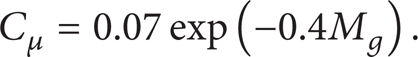
The simulation results of cross-stream velocity fluctuations

Cross-stream distributions of velocity fluctuations at x = 78 mm.
Cross-stream distributions of velocity fluctuations at x = 125 mm.
From a qualitative point of view, it can be seen that a similar trend of velocity fluctuation distribution is obtained by all the five cases, and the agreement between computation and experimental values is fairly good. From a more quantitative point of view, it should be firstly noted that the simulation results obtained by the standard k-ω SST model are overpredicted with respect to experimental data, which is in accordance with the analysis mentioned above. The various compressibility modifications were proposed just for suppressing the excessive growth of TKE.
It is seen that the dilatation compressibility correction exhibits satisfactory performance at both of the two streamwise locations. The velocity fluctuation maxima predicted by the dilatation compressibility correction at the two positions are about 9.5% and 11.8% lower than those of the standard k-ω SST model, illustrating the good applicability of that modification.
For the structural compressibility correction, its results show the best agreement with experimental data in the vicinity of upper and lower walls (y < 15 mm and y > 35 mm) between all the five cases. It is believed that the introduction of gradient Mach number M g brought the excellent results. But in the central flow field the correction effect is unnoteworthy at x = 78 mm or even negative at x = 125 mm.
For the shock unsteadiness correction, it is noted that its results are nearly the same as those of the standard k-ω SST model at both of the two locations, despite only little difference. That may be due to the fact that the strength of shock wave is fairly weak at those positions, where expansion waves have the predominant influence. So the shock unsteadiness correction has no effect actually on the flow field.
For the coupling case, that is, the k-ω SST model with all the three corrections, its results are the combination of all the three kinds of compressibility modifications mentioned above, so, naturally, the best agreement is obtained by this case generally. However, in this test case, it seems that the coupling case results are more close to that of the dilatation compressibility correction case, and in near wall region the coupling case results are not as good as that of the structural compressibility correction case.
Figures 6 and 7 demonstrate the computed and experimental values of velocity u at x = 78 mm and temperature at the location x = 125 mm, respectively. Compared with Figures 4 and 5, it is noteworthy in Figure 6 that the correction effects on velocity distributions are similar to those of the velocity fluctuations distributions. The structural compressibility correction and the coupling case improve the prediction accuracy in the near wall region; however, they bring about negative effects in the central flow region. In Figure 7, it can be seen that all the five cases give almost the same results for temperature distributions except the central flow region. That may be caused by the fact that the solution of energy equation is only indirectly affected by the turbulence closure. In addition, it is noted that the temperature maximum at x = 125 mm is underestimated by the five cases here. That may be caused by the imperfect prediction of the complex shock wave structure, which has an influential effect on the location of reaction zone. Such discrepancies are also observed in the numerical study conducted by Oevermann [23] and Mura and Izard [26].

Cross-stream distributions of velocity u at x = 78 mm.

Cross-stream distributions of temperature at x = 125 mm.
3.2. Hydrocarbon-Fueled Supersonic Combustion Simulation
The hydrocarbon-fueled scramjet model considered here is the same as the one studied experimentally by Situ et al. [27]. To avoid ignition difficulty of hydrocarbon fuels (usually kerosene) in supersonic flows, the configuration named dual-combustor ramjet (DCR) was employed in their experiment. Supersonic fuel-rich hot gas was generated from the combustion process of liquid kerosene in the subsonic dump combustor, which was then injected into the supersonic combustor in parallel with the vitiated air stream. Since ethylene (C2H4) was the primary product of thermal decomposition of kerosene, it can be approximately regarded as the fuel gas composition in the calculation.
Figure 8 shows a sketch of the model combustor with the relevant geometric dimensions for the simulations. The combustion chamber consists of a constant area segment and a one-sided divergent channel with an angle of 3.6°. The total length of the combustor is 1100 mm and the heights at the inlet and outlet are 65 mm and 110 mm, respectively. In addition, a step of 6 mm is located between the air stream and the fuel stream at the inlet.

Schematic of the hydrocarbon-fueled combustor.
The computational domain is meshed with a structured grid of 12,505. Local refinement has been made near the boundary region and the shear layer. The inflow conditions of air and fuel jet are given in Table 2. The boundary treatment is similar to that of the hydrogen-fueled combustor case.
Inflow conditions of test case 2.

Again, the five cases using standard SST model, three kinds of compressibility modifications, and their combinations are performed, just like in the hydrogen-fueled case.
The static pressure field obtained by the standard SST model is illustrated in Figure 9. It is seen that the sharp rise and fall of pressure in the constant area duct are caused by the complex shock wave structures. The shock train gradually decays along the combustor length and disappears in the divergent segment.

Static pressure contour.
Figures 10(a) and 10(b) show the predicted wall surface pressure distributions compared with the experiment data at the upper wall and the lower wall, respectively. A close agreement with the experiment has been obtained for all the five cases, validating the reliability of the in-house code in hydrocarbon-fueled scramjet simulation. It should also be noted that the calculation results of wall pressure distributions are not sensitive to the turbulence model. Only some minor differences can be found between the five cases. That may be due to the fact that the wall pressure is only affected indirectly by the turbulence model and the correction effect of different compressibility modifications will be compared in the analysis of the TKE distributions in detail.

Simulation results of wall pressure distributions: (a) upper wall; (b) lower wall.
Comparisons of the cross-stream TKE profiles at several locations along the combustor length are presented in Figure 11. It illustrates that all the five cases exhibit similar trends of the TKE distributions. Peak values of TKE are found in the shear layer region, where the air flow and the fuel flow exchange energy and velocity fluctuates intensely.

Simulation results of TKE at different streamwise locations.
Similar to the former hydrogen-fueled scramjet case, the dilatation compressibility modification has a fairly good correction effect in suppressing the overlarge growth of TKE at all the three positions. In contrast, the correction effect of the structural compressibility modification is unremarkable or even negative. More important, it is noted that the correction effect of the shock unsteadiness modification is much more noteworthy than the other two modifications, especially in the forepart of combustor. In shock unsteadiness modification, the maxima of TKE at x = 0.05 m, 0.4 m, and 0.8 m are about 46%, 72%, and 93% of those computed by the standard SST model, respectively. This phenomenon can be explained by the fact that the shock wave strength gradually decays along the constant area segment and in the divergent part the strength declined sharply, as illustrated in Figure 9. Therefore, it is verified that the correction effect of the shock unsteadiness modification is proportional to shock wave strength. In addition, as a combination of the three modifications, the coupling case gets the most striking suppression effect of TKE, naturally. It is implied that a better prediction could be achieved by the overlying effects produced by different corrections.
In brief, overpredicted TKE obtained by the standard k-ω SST model will cause an overestimation of turbulent viscosity and consequently lead to the inaccuracy of the mean flow field simulation. Therefore, appropriate compressibility modifications should be incorporated into turbulence models in the supersonic numerical simulation.
4. Conclusions
Five cases employing different turbulence model compressibility modification combinations have been conducted in simulations of a hydrogen-fueled and a hydrocarbon-fueled scramjet combustor, respectively. The common trends of the correction effects of the different compressibility modifications obtained by the two test cases can be summarized in the following points.
The correction effects of compressibility modifications on the TKE and velocity are much remarkable than those on temperature and wall static pressure distributions. Generally speaking, the excessive growth of TKE is effectively depressed by the three kinds of compressibility corrections and the mixing process is retarded to a more reasonable level.
The dilatation compressibility modification has the best versatility. In both of the two test cases and at all the locations along the combustor length, this correction model always demonstrates the effective suppression of TKE.
The structural compressibility modification shows best agreement with experiments in the near wall region in the hydrogen-fueled scramjet case; however, the correction effect yielded by this model is unremarkable or even negative in the central flow field.
The correction effect of the shock unsteadiness modification is sensitive and proportional to shock wave strength. Influence yielded by this model in the strong shock wave region is much more noteworthy than that of the other two corrections.
As a natural result, the correction effect of the coupling case is more remarkable than the three single modifications in most situations. It is illustrated that the overlying effects between different correction models may improve the prediction accuracy; however, the mechanism of the coupling effects still needs further investigation in future work.
Conflict of Interests
The authors declare that there is no conflict of interests regarding the publication of this paper.
Footnotes
Acknowledgments
This work was supported by National Natural Science Foundation of China (50306011) and Scientific Foundation for Returned Overseas Chinese Scholars. Their support is gratefully acknowledged.