
Abstract
A second-order elastic analysis of tapered steel members with I-shaped sections subjected to span distributed and concentrated loadings is developed. Fixed end forces and moments as well as exact stiffness matrix of tapered Timoshenko-Euler beam are obtained with exact geometrical properties of sections. The simultaneous action of bending moment, shear, and axial force including P−δ effects is also considered in the analysis. A computer code has been developed in MATLAB software using a power series method to solve governing second-order differential equation of equilibrium with variable coefficients for beams with distributed span loading. A generalized matrix condensation technique is then utilized for analysis of beams with concentrated span loadings. The accuracy and efficiency of the results of the proposed method are verified through comparing them to those obtained from other approaches such as finite element methods, which indicates the robustness and time saving of this method even for large scale frames with tapered members.
1. Introduction
Tapered members are used in many structures such as sloped frames, bridges, and multistory buildings as well as mechanical components. Because of the ease of construction, the use of I-shaped members with a linearly variable depth of web is more practical; moreover, weight optimization, stability increase (Timoshenko and Gere [1] and Lopez [2]), flexibility in fabrication and design, and sometimes satisfying architectural considerations are some advantages which rolled members cannot provide. Therefore, an exact analysis of structures containing this kind of members is very important. On the other hand, according to the AISC-2010 [3], the required strengths of components of structures should be determined by using a second-order analysis method. This kind of analysis can consider flexural, shear, and axial member deformations; both P − Δ and P − δ effects (Chen and Lui [4]); and all gravity and other applied loads that may influence the stability of the structure. Consequently, a direct analysis method for design of structures containing tapered members which are subject to nodal and span loading is of high significance.
In addition to classic methods, in recent decades, different approaches have been developed for second-order and buckling analysis of tapered members. Timoshenko and Young [5] suggested the division of the tapered members to subelements for analyzing the structure. Despite the simplicity of this method, they do not have the required precision for an exact analysis (as illustrated in example 1).
Numerical methods such as finite element method (e.g., Bathe [6]) and direct integral method (e.g., Karabalis and Beskos [7]) have been used for producing stiffness matrix of member. These methods achieve relatively good precision by choosing fine mesh in modeling; however, Numerical methods such as finite element method is highly time consuming due to its great number of finite elements, especially in the case of large structures. Therefore, these methods are not conducive to daily use because of high computational costs.
Al-Gahtani [8] obtained axial, torsional, and flexural stiffness matrix separately as well as fixed end forces and moments through solving governing equilibrium equations of member based on the boundary integral method. This study considers the span loadings on tapered beams; however, it ignores the second-order effects associated with P − δ and simultaneous action of shear and bending deformation.
Li et al. [9–11] have solved tapered Timoshenko-Euler beam element using Chebyshev polynomial approach considering simultaneous effects of axial force, shear deformation, and P − δ effects with nodal loads. The exact stiffness matrix is derived based on beam-column theories taking into account second-order effects in governing equilibrium differential equation. This approach contains less computational effort and is also more time saving and practical in advanced analysis of structures; nevertheless, span loadings have not been considered in this method despite their importance in practical analysis.
This paper, alternatively, takes into account not only nodal loads but also distributed and concentrated span loads (Kim et al. [12]). A practical method for second-order analysis of steel tapered members is presented considering the simultaneous effect of bending moments, axial forces, and shear deformations (including P − δ). To fulfill this purpose, a power series method is used to solve the equilibrium differential equation to obtain exact elastic stiffness matrix and fixed end forces and moments. In the offered examples, the effect of axial pressure forces and shear deformations is clearly observable in reduction of element stiffness. Although only elements with I-section and linear variation of depth are considered in this study, the proposed method can be developed for other states. The algorithm presented in this paper can be used for direct analysis method considering requirements based on AISC code [3].
2. Derivation of Element Formulation
The general form of members considered in this paper is shown in Figure 1 which reveals linearly symmetric tapered web and I-shaped section with constant width and thickness of flanges. It is assumed that the element is braced laterally while local buckling of the web and flanges is not taken into account. All elements are initially straight and the cross-sections of the beam remain plane after deformation. Stiffness matrix and fixed end forces and moments have been obtained for tapered members in this section. The element formulation is based on the exact moment of inertia of section with no approximation.

I-shaped section members with tapered web.
2.1. Geometrical Properties of Section
The exact formulation of area and inertia moment of the cross-section at location z as shown in Figure 1 is obtained as follows:

where D(z) = D1 + s·z, s = (D2 − D1)/L, and Aw(z) is web area at location z and equal to overall depth time web thickness (AISC-2010 [3]). In most of the existing researches, approximate formulation has been used for calculation of inertia moment. This approximation creates considerable error in structural analysis results including displacements and forces. Some approximate formulas are shown in Appendix A.
2.2. Members Subject to Uniform Distributed Span Loading
Tapered beam-column element of this research including uniform distributed span loadings and applied conventions is shown in Figure 2.

Tapered beam of the paper, the used conventions and uniform span loadings.
In deriving stiffness matrix and fixed end forces and moments of tapered members, the simultaneous effect of bending moment and shear and axial force is considered. In so doing, the equilibrium differential equation of the tapered Timoshenko-Euler beam element is established, in a similar way to G. Q. Li and J. J. Li [9], in order to compare the obtained relations. Equation (2) is the governing equation for the equilibrium of tapered Timoshenko-Euler beams without span loadings (Li et al. [9–11]):

where α(z) = E·I(z)·γ(z),
E and G, respectively, are elastic and shear modulus. In this section, the governing equilibrium equation (2) is reestablished taking into account uniform span loadings.
Element deflection consists of two sections: one is induced by the bending deformation and the other by shear deformation; moreover, the axial deformation due to axial forces is taken into account separately:
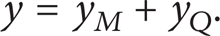
Second derivation of (3) can be expressed as follows:

Substituting y M ″ and y Q ″ terms by relations obtained from (5) and rearranging terms for y″, y′, and y, the governing equation for the equilibrium of tapered Timoshenko-Euler beam is obtained as (6):
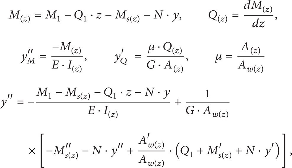

where Ms(z) is the moment created by span loadings at distance z from the left end of the element and α(z) = E·I(z)·γ(z),
For converting (6) to nondimensional form let ξ = z/L:

Equation (7) can be used for all tapered members with any sections and all forms of span loadings. Using (8) for uniform span loadings (q as in Figure 2) and I-shaped section, (7) is converted to (9); namely,


To solve differential equation (9), power series method is used for y, α, and β:

Differentiating equation (10) term by term with respect to ξ and substituting them into (9), we arrive at the result and after a further differentiation we have

Separating out the terms corresponding to n = 0, n = 1, and n ≥ 2, and then the equalization of relevant coefficients in two sides of (11), for n = 0, it becomes:

for n = 1,

and finally for n ≥ 2,

where [2/n] = 1, for n = 2, and [2/n] = 0, for n > 2.
Recurrence relation for n ≥ 2 using (13) can be written as

Thus, considering (14), it can be concluded that any y n (for n ≥ 4) can be expressed in linear combination of y0, y1, y2, y3, Q1 and the constant value of c5 as

Hereafter, these parameters must be obtained to determine y for different values of z. It should also be mentioned that M1 is unknown and appears in y n (for n < 4). From (5) and considering y′ = y M ′ + y Q ′ and y M ′ = θξ,

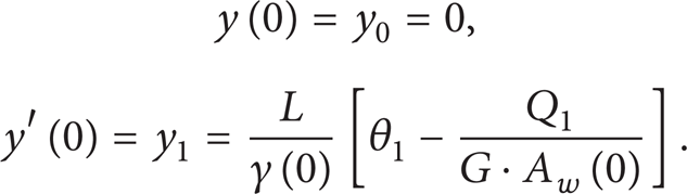
Using boundary condition, (15), and (16).
For ξ = 0,
For ξ = 1,
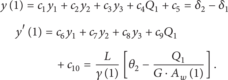
Using first relation of (10), separating out the terms corresponding to n < 4, collecting all the remaining terms under a single summation sign, and considering (18),

Applying the below conditions to (19), coefficients c1 to c10 are derived:

Now (12a), (12b), (17), and (18) can be used for obtaining unknown factors y0, y1, y2, y3, Q1, and M1 in order to find function y(z) for all values of z. Q2 and M2 can be found from equilibrium of element as

On the other hand axial stiffness matrix of element can be derived separately as

where k a = E/∫0 L (1/A(z))dz.
Solving the obtained relations for δ1, θ1, δ2, and θ2 yields stiffness matrix and fixed end forces and moments in the following form:

where

It should be mentioned that, by substituting (21) into (23), we have
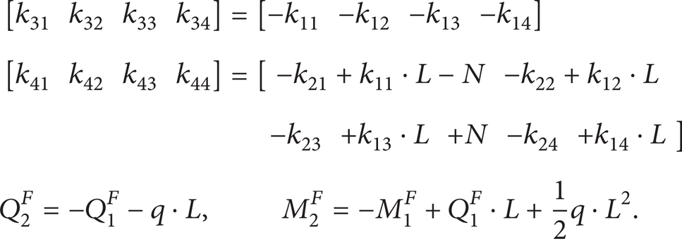
In (24) [K], {Δ}, {P}, and {P F } are elastic stiffness matrix of element, displacement vector, force vector, and fixed end forces and moments vector, respectively; u1 and u2 are axial displacement of element nodes. Component of stiffness matrix [K] and vector {P F } are represented in Appendix B. Stiffness matrix is symmetric and there is no need for calculating all components of it. This subject is illustrated in example 1.
2.3. Members Subject to Concentrated Span Loading
In this part, a static condensation method is used for obtaining the stiffness matrix and fixed end forces and moments of the element. McGuire et al. [13] contracted the stiffness matrix of an element with eliminating certain degrees of freedom. Similar approach is used to establish formulation of the element with concentrated span loadings. To this purpose, the element is divided into two parts at the concentrated load location, as in Figure 3, and the stiffness matrix of each part is calculated from (24). Then, displacement quantities at division section are eliminated so it becomes possible to calculate fixed end forces and moments independently of the intermediate displacement vector. Consequently, this approach requires less number of arithmetical operations than those with no condensing. It should be mentioned that the stiffness matrix obtained from the proposed approach is the same as that calculated through (24). But in the presence of concentrated span loadings, fixed end forces and moments and the stiffness matrix of element are obtained. The proposed formulation is established as follows.

Divided tapered beam with concentrated span loadings.
The force-displacement relation of parts (a) and (b) is [K1]{Δ1} = {P1} and [K2]{Δ2} = {P2}, respectively, where
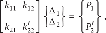

[K1] and [K2] are stiffness matrix of parts (a) and (b), obtained by (24).
Assembling Equations (26) and (27) together, we have:

in which,
is desired.
After solving recent relation for Δ2 and substituting it in the first and third rows of (28) the following equation is obtained which is independent of Δ2:

Obtained relation is in the form of {P} = [K]{Δ} + {P F }, where {P F } is fixed end forces and moments:

And stiffness matrix [K] is

Example 2 indicated that matrix [K] is the same stiffness matrix of whole member with no division. So it is enough to calculate k12, k22, and k32 to find fixed end forces and moments. It should be mentioned that axial stiffness matrix components can be calculated in a similar way to that in the previous section.
3. Numerical Examples and Verification
This section offers some examples to verify the accuracy of obtained relations; in this measure, the deflection and normal stress of beam-column elements in the proposed method are compared with the results of other studies and finite element method. The examples also reveal the symmetry of the stiffness matrix.
3.1. Beam Column Subject to Uniformly Distributed Span Loadings
The tapered fixed-hinged beam in Figure 4 is similar to G. Q. Li and J. J. Li example [9]; however, in this study it is subject to uniform distributed span loadings where maximum deflection and its location are calculated. Table 1 shows the comparison of the results of the proposed method obtained in MATLAB [14] software to those of FEM with 50 and 10 mm mesh size and also to the beam subdivided into five segments of equivalent nodal loads. It also indicates the effect of pressure axial force and shear deflection. To generate the results for verification, the ABAQUS [15] four-node shell element S4R is employed for modeling the beam as in Figure 5. The results demonstrate an acceptable accuracy of the proposed method. The investigations revealed that choosing number 14 for polynomial term is acceptable in calculating deflections. In all examples of this paper, elastic and shear modulus are 206 and 80 KN/mm2, respectively.
Maximum deflection of fixed-hinged beam (mm).

Case A: both axial and shear; B: no axial; C: no shear; D: no axial nor shear.
*Maximum deflection location from first of beam (mm).
**Errors: calculated compared to FEM with 10 mm mesh size.
Tapered beam with uniformly distributed span loadings.

Finite element model of tapered beam.
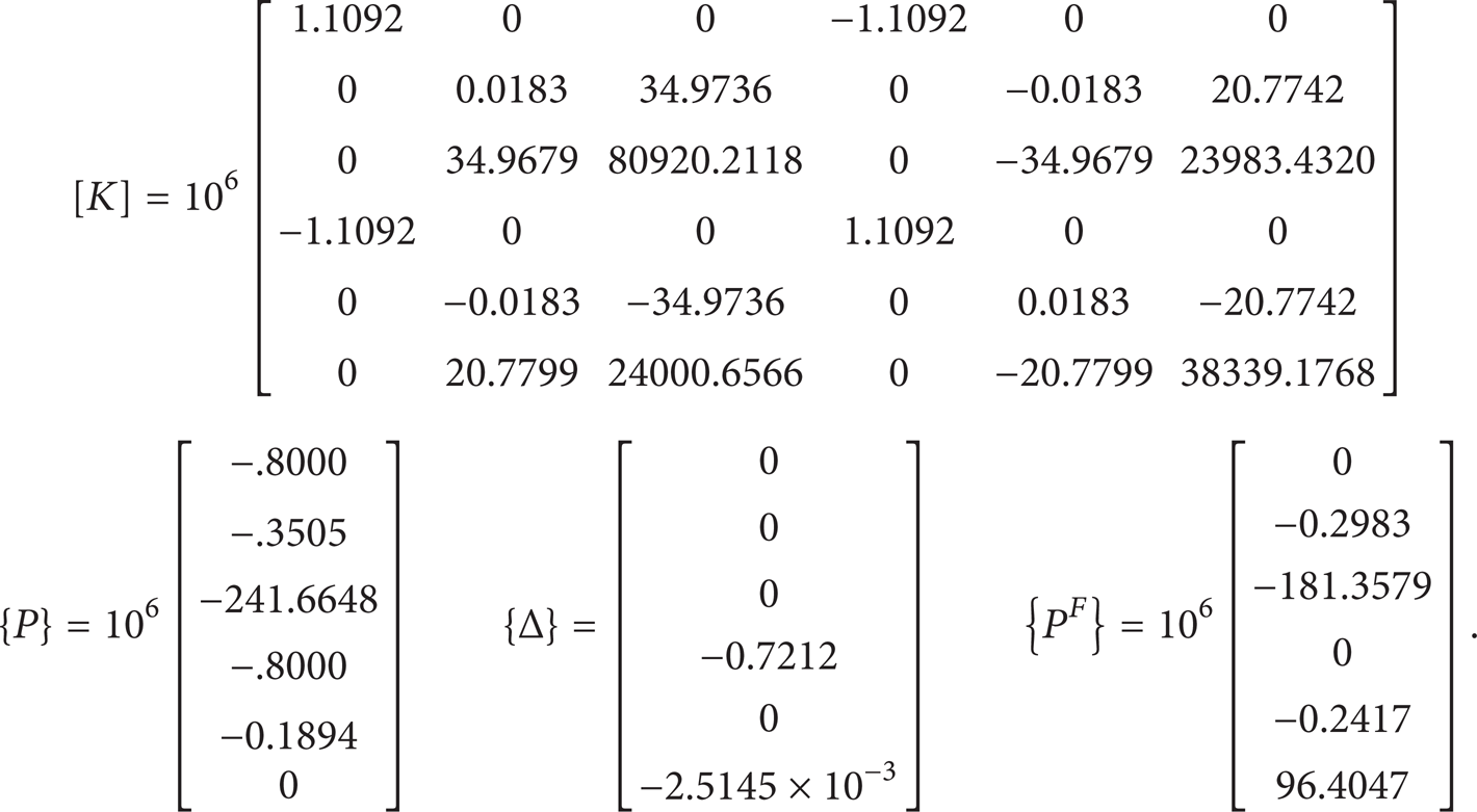
Stiffness matrix [K] and fixed end forces and moments {P F } are shown below; it can be seen that matrix [K] is symmetric and also reduces computational efforts of calculation:
3.2. Beam Column Subject to Concentrated Span Loading
Calculating the deflection at midspan of steel tapered fixed-hinged beam of G. Q. Li and J. J. Li [9] is considered in Figure 6. The results of the proposed method are compared to those of FEM with 50, 20, and 10 mm mesh size and those of Li et al. study (Table 2). G. Q. Li and J. J. Li divided the member into two parts and derived stiffness matrix of each part individually; they also utilized FEM by dividing the element into 10 segments in its length to calculate deflection. Because of the same axial loads in the two parts of the beam while dealing with elastic analysis, the stiffness matrix of the whole member in this example is the same as that of the previous one.
Deflection at middle of fixed-hinged beam (mm).

Case A: both axial and shear; B: no axial; C: no shear; D: no axial nor shear.
*Errors: calculated compared to FEM with 10 mm mesh.

Tapered beam with concentrated span loadings.
3.3. Gable Frame with Tapered Members and Span Loadings
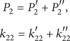
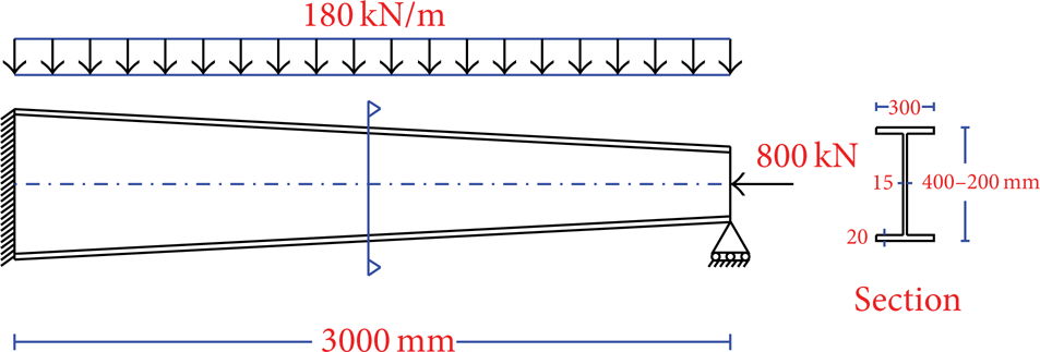
This section takes into account a very applicable single bay gable frame shown in Figure 7; similar to previous examples the results were verified by ABAQUS with 50 mm mesh size. To this purpose, maximum deflection and normal stress at the tip and corner of the frame and also the effects of shear deformations and P − δ on deflections are taken into consideration (Table 3). These results evidently expose the efficiency of the proposed method in practical problems. It should also be mentioned that, in the proposed method, the elements are modeled symmetrically over their longitudinal axes.
Response of gable frame.

Case A: both axial and shear; B: no axial; C: no shear.
*Errors: calculated compared to FEM with 50 mm mesh.

Gable frame with tapered members and span loadings.
4. Conclusions
This paper investigated second-order nonlinear analysis of tapered Timoshenko-Euler beam-column element subjected to span loadings. Thus, a power series method was used to solve governing differential equations of the member equilibrium. According to examined examples, the appropriate number of terms for power series became 14 to achieve adequate precision and speed. The effect of shear displacements and pressure axial forces in the reduction of beam-column element stiffness is obviously recognizable in the solved examples. The high speed of the proposed method, its adequate precision and accuracy, and its simplicity in modeling make it a more effective and practical method compared to others such as finite element method. The required analysis time of the proposed approach for the first example is only 0.09 seconds, while it is 0.7 and 17 seconds for the finite element method with 50 and 10 mm meshes, respectively. The offered method can be applied in 2D large scale practical structures and also be generalized to spatial ones. Moreover, it can be developed in various mechanical component analyses such as rotating flexible taper beams and roof-crane taper bridges.
The proposed formulation can also be derived for each section shape, nonlinear variation of the section along member, and arbitrary distribution of span loadings. Therefore, member weight can also be considered in the analysis. Future work should include material nonlinearity and other conditions of steel design codes in order to achieve more advanced and direct analysis of frames including tapered members. Also, reliability analysis of tapered mechanical components subjected to harmonic excitations can be accomplished, like Rahbari et al. [16].
Footnotes
Appendices
Conflict of Interests
The authors declare that there is no conflict of interests regarding the publication of this paper.