
Abstract
The aim was to redesign and manufacture of a shovel for a pull-type land levelling machine, which, in its present condition, is used to get easily damaged even under low loads. Firstly, the maximum pulling load affecting the levelling shovel was experimentally determined. Then, stable-shovel system with the bolt connection was replaced with a bearing-shaft connection system. In this way, the new shovel has gained a capability of making oscillation motion so that it can operate on sloped grounds. CATIA program was used in the design studies. The shovel system was investigated by assembly structural stress analyses. This new construction enabled the system to operate 3 times more securely at maximum stress conditions without changing the levelling shovel material. Thus, it is managed to prevent any possible damages that might occur due to maximum loading conditions of the system. Besides, displacements that occur on the shovel decreased at the rate of 90%.
1. Introduction
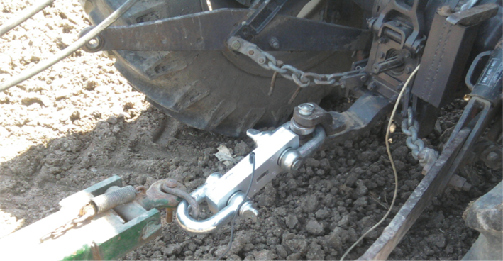
Land levelling machines are classified under the category of scraper, conveyor, and spreading machinery. General working principle of such machinery is to level the surface of the ground over which the machine travels by cutting off the topographically high spots on the surface of the ground and then to push the volume of loose dirt forwardly until a low spot or depression in the surface of the ground is encountered. A land levelling machine, therefore, has a rigid blade capable of cutting grounds. Furthermore, there is a volume carrying the cut-out ground material just above the blade, as shown in Figure 1. The volume just above the blade carries the cut-out ground material on its curved surface which is named as shovel. Maximum load value applied to a pull-type land levelling machine is determined with respect to the maximum pulling force of that land levelling machine. The preferred pulling force/shovel width value, on average, for medium-firm grounds is about 30 HP/m. Depending on the increased pulling force values, the shovel construction system and dimensions have been changed, but not the shovel material itself.

Photographic view of shovel and blade.
In the levelling operation conditions, there exist ground uncertainties and varieties. When the shovel encounters hard ground in the course of the normal operation speed (5–7 km/h), the puller applies its maximum pulling force onto the levelling machine. Under these circumstances, the load that is applied to a certain section of the surface of the shovel or distributed to the whole surface of it may damage the shovel. Size of the damage may change depending on the section of shovel exposed to load. The failure would go up when the whole load is applied to the side plate of the shovel or on a certain section of the shovel, for example, on a 100 mm wide section. Such failures decrease the performance or result in a failure by causing faulty ground levelling at any time during the levelling operation. The above mentioned reasons necessitate the usage of the computer aided engineering tools in the design and analyses of the construction. In this way, it would be possible to develop a successful design by preventing the possible failures or by indicating the places of potential failure.
Computer aided engineering (CAE) is the best method to deal with a construction, taking into consideration multiple perspectives. The designs that are produced in computer environment can be reevaluated through appropriate computer analyses. In a real design, when it is intended to carry out a product development work on the existing system, modelling this existing system through the computer is an important step. This computerized model can represent the existing system precisely. Another important point to be taken into consideration in the real product development work is the manufacturability of the design. The design produced by computer aided engineering tools can provide very successful values. A design that cannot be manufactured or has no meaningful reason to be manufactured will stay in its virtuality in the computer environment; or if such a design is transferred to manufacturing, it will cause great economic losses. Therefore, methodical construction principles should be followed during formation of a construction [1]. A construction is designed in accordance with the mentioned principles, its objectives, and dimensions; thus, design sections are determined in accordance with the system requirements by conducting repeated stress analyses.
Stanova et al. [2] developed the geometric parametric equations and implemented them in CATIA software code for the geometric modelling in order to obtain the finite element analysis of helical wire standards. Iqbal et al. [3] performed an analysis using CATIA in order to change in blade design of turbo molecular pumps which is mostly used in vacuum technology. The cause of the failure in the vital part of the crawler travel gear of the BWE was analyzed in the light of the FEM results by Bošnjak et al. [4]. Bošnjak et al. [5] investigated the causes of chain links breakdown of the Stacker Crawler by means of working stress by applying FEM. Wang et al. [6] focused on an investigation of computer aided fixture design in the past decade. In the mentioned study, it is shown that most of the studies on this subject have been done by FEM. Structural analysis of a helical bimetallic strip thermostat was analyzed by Zaharia [7] using CATIA workbench. In order to obtain the finite element model, the tetrahedral elements were used for both types: linear and parabolic. In another study Zaharia [8] analyzed the Von Mises stresses of several constructive types of claw couplings using CATIA. Mahardika et al. [9] performed a theoretical study for the best design and analysis of dynamic compression plate by CATIA which is commonly used in medical industry. Simulating the stress analysis of a low loader structure was carried out by Nor et al. [10] with a commercial software called CATIA.
In this present study, the existing construction of the shovel of a land levelling machine which is activated by a puller with 100 HP engine power was redesigned in accordance with the working conditions of the shovel. A shovel-shaft connection system was designed by changing the base frame connection system of the shovel. This new construction enabled the system to operate 3 times more securely at such conditions, when maximum pulling force of the puller is applied to the system, without changing the shovel material. Thus, it has been possible to prevent any possible failures that might arise from maximum stress conditions of the system. CATIA program was used in the design stages of the study.
2. Modelling of the Existing Shovel System Using Computer Aided Design
2.1. Determining the Maximum Force Value Affecting the Ground Levelling Shovel
In this study, the maximum pulling force value that may affect the shovel which is activated by a 4 × 4 puller with 100 HP engine power in the course of the normal operation speed (5–7 km/h) was experimentally determined before starting the computer aided design. By using a load cell with the load capacity of 20 tons as illustrated in Figure 2, the maximum pulling force value applied to the system by the puller was determined as 34 kN.
Load cell used in the experiments.
2.2. Computer Aided Stress Analysis of the Existing Design of Shovel
Geometric dimensions and widths of levelling shovels may change depending on workloads and requirements. The shovel examined in this study belongs to a pull-type land levelling machine used on soft and medium-hard grounds. The existing shovel with a width of 3200 mm and that is connected to base frame with bolts, as seen in Figure 3(a), was examined and improved according to the design objectives by using computer aided engineering. First of all, three-dimensional models of the shovel and the connection system of the shovel were created with CATIA, and then transferred to computer environment and given in Figure 3(b).

Original shovel connection system.
As explained above, maximum load that may be applied to the shovel is 34 kN. Based on the width of the shovel, maximum pulling capacity to be used in the new design is 40 kN. Finite element model of the system was developed with mesh sizes determined by the researchers and shown in Figure 4. This model consists of 38805 nodes and 116822 linear elements. Mesh sizes can be reduced depending on the computer capacity, but reducing the mesh sizes does not mean getting more accurate results.
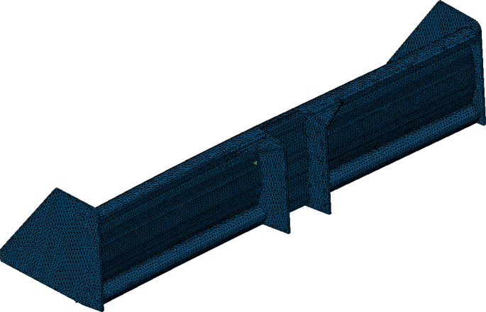
FEM model of original shovel.
Under normal working conditions, a load of 40 kN is applied to the shovel as a distributed load. But, depending on the conditions of use, maximum load may sometimes affect an edge point of the shovel at a distance of 1600 mm from its center, and this is the maximum stress condition of a cross-section unit. The finite element model which was created for this stress condition was analysed and, as shown in Figure 5(a), maximum Von Mises stress value on the system was determined as 373 MPa. This value is higher than the flow stress of St 37, the shovel material. It is quite obvious that the shovel would undergo plastic deformation under such stress. In the case that the load of 40 kN affects the blade as distributed load (general working condition), however, the maximum stress value measured on the shovel cross-section, as shown in Figure 5(b), is 124 MPa. This value is approximately half of the flow stress of the shovel material and that seemed to be appropriate. In addition, in the case that the load is applied to an edge point of the shovel, a displacement of 14.4 mm will occur at the side plate of the shovel. This value is quite huge for the shovel system. In the case of a distributed load condition, however, the maximum displacement value at the shovel is only 3.3 mm and the displacement values of either of these cases are shown in Figures 6(a) and 6(b).
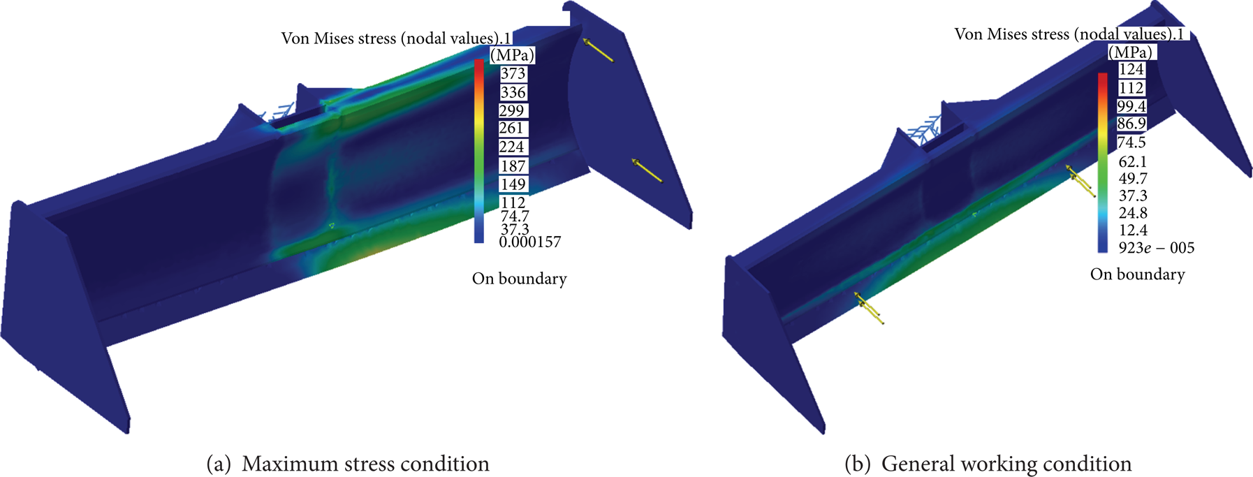
Maximum Von Mises stress on the shovel.

Displacements and their places on the shovel.
3. Redesign of Current Land Levelling Blade System by Computer Aided Design
3.1. Design of the Shovel-Shaft Connection System
In the existing system, the load carrying capacity of the shovel is low and not suitable to operate on the sloped ground surfaces. Therefore, the aim was to have the system gained a capability of 11° of oscillation motion with respect to the horizontal axis. For this purpose, it is intended, in the first place, to convert the shovel-bolt connection system shown in Figure 3(a) into the shovel-shaft connection system shown in Figure 7(a). Analysis of the new model in this design has proved that just this arrangement alone is able to decrease the maximum Von Mises stress at the rate of 22.5% and thus reduce to 289 MPa, as shown in Figure 7(b).

Redesigned shovel connection system.
3.2. Base Frame Column Sizing and Shaft Design
In order to get consistency of the developed ground shovel with the existing base frame profile, blade-bearing column dimensions are determined to be 315 mm × 310 mm × 10 mm. It is obvious that shaft diameter will be smaller than 315 mm depending on the base frame column profile dimensions. Shaft flange was designed to have a diameter of 350 mm and 10 bolt holes. There are two main factors determining the shaft outer diameter. The first is strength and the second is bedding problem. Due to wall thickness of the base frame profile and constructive necessities in the shaft bedding, it has been determined that the maximum diameter of shaft could be 240 mm. In the case of the connection condition shown in Figure 8(a), however, the Von Mises stress increased to 440 MPa value at maximum stress conditions (Figure 8(b)). An arm support system, as illustrated in Figure 9, was designed in order to be able to select a smaller shaft diameter and to ensure rotational motion of the shovel.

Shaft design.
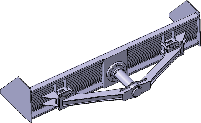
Solid model of arm support system.
3.3. Shaft Bearing and Analyses
The shaft added to the system was designed to have 2 bearings. Base frame column not only limits the maximum outer diameter of the shaft, but also limits the L distance between the bearings as shown in Figure 10(a), because the bearings were designed to place within the base frame column. If the L distance is kept small, this will cause an increase of the loads acting on the A and B bearings as shown in Figure 10(a). The L distance for the base frame column of 310 mm in length was determined to be 280 mm, and the A and B radial bearing loads were calculated as 228.57 kN by using MdSolids program. Axial bearing load, however, is 20 kN and is also seen in Figure 10(b).
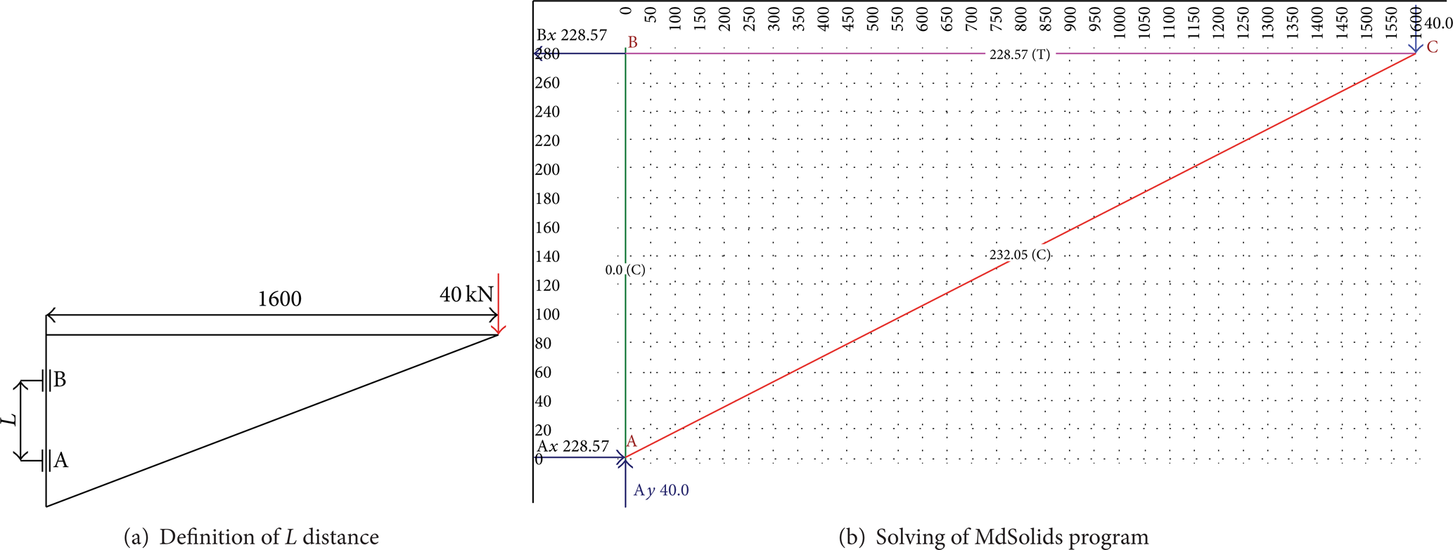
Solving of shaft bearing load problem.
To enable the A and B bearings to carry the loads 2 times securely, the radial load value is determined as 457.14 kN and the axial load value is determined as 40 kN. But, considering that the system will have oscillation motion, it would not be true to select the bearing on the basis of only the loads acting on the bearings. For the shovel which makes oscillation motion, the oscillation angle is φ = 2β = 22 degree. Total oscillation angle, as shown in Figure 11, is 4β. An oscillation cycle takes place for a certain time (t) for trip of 0–4 distance and t = 9.59 sn in our system.

Oscillation motion.
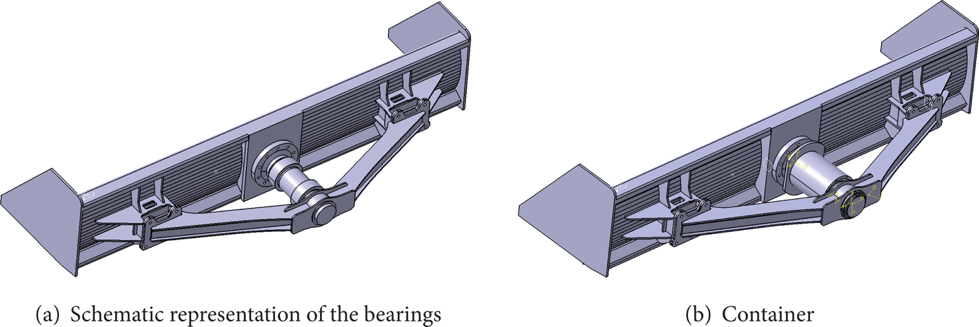
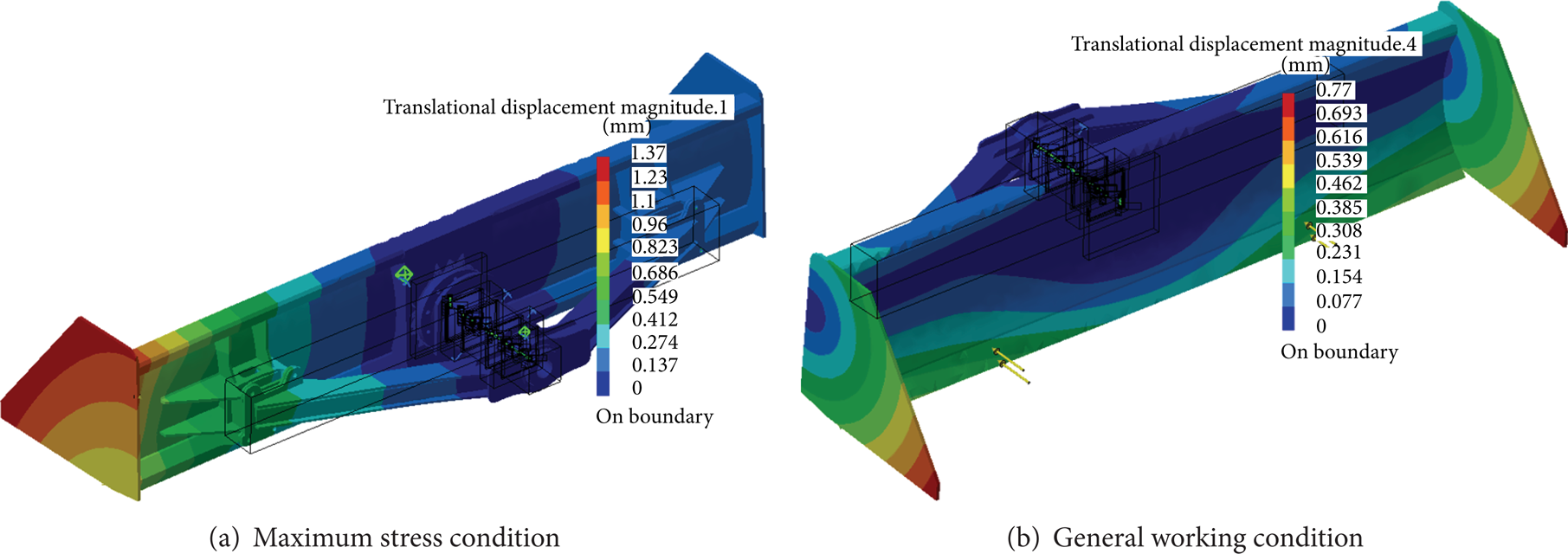
In consideration of these load values, the bearing to be selected will be appropriate for an oscillation motion which will continue for a time period of 10.000 hours under 0.5 Hz dynamic loading and at −15°/50°C working temperatures. As the ball and roller bearings are not suitable for oscillation motion, in this study, it was decided to use radial spherical plain bearing in the design. The possible minimum inner diameter of the bearing to be used in the construction was calculated on the interface page of the website of SKF, the manufacturer. Inner diameter of the bearing coded SKF GE 160 TXG3A-2LS which is expected to carry previously calculated radial and axial loads for a time period of 10.000 hours has been determined to be 160 mm. Figure 12 is a display image of the SKF online life time calculation screen. Thus, the outer diameter of the shaft, which was previously designed to be 240 mm as shown in Figure 8(a), will be 160 mm, depending on the selection of bearing. Figure 13(a) illustrates an assembly of bearings used in the system. In order to provide an interconnection between base frame and outer rings of the bearing, a container, as shown in Figure 13(b), has been included in the design. As the shaft diameter is determined on the basis of the bearing life time calculation, it should also be examined by assembly structural stress analysis. For this purpose, a FEM model was created for the new condition of the assembly system and was shown in Figure 14. Results of the Von Mises stress analysis according to the maximum stress condition for the assembly system given in Figure 14 are presented in Figure 15(a). In the critical zone of the redesigned shovel, the maximum stress obtained was 73.8 MPa and this value is lower than the minimal value of the flow stress of base material for about 3 times. Furthermore, as previously planned, the maximum stress has been directed to occur on a relatively easily repairable section of the construction. The stress analysis of the general working condition is also shown in Figure 15(b). Displacement values for the present condition of the developed construction are given in Figure 16. As seen in the figure, the displacement values for either the maximum stress condition or general working condition are quite appropriate. Obtaining the maximum displacement values at the side plate of the shovel is an expected condition.
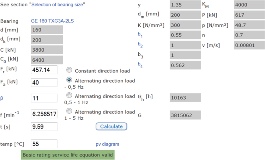
Online life time calculation screen.
Solid model of assembly of bearings.

FEM model of redesigned shovel.
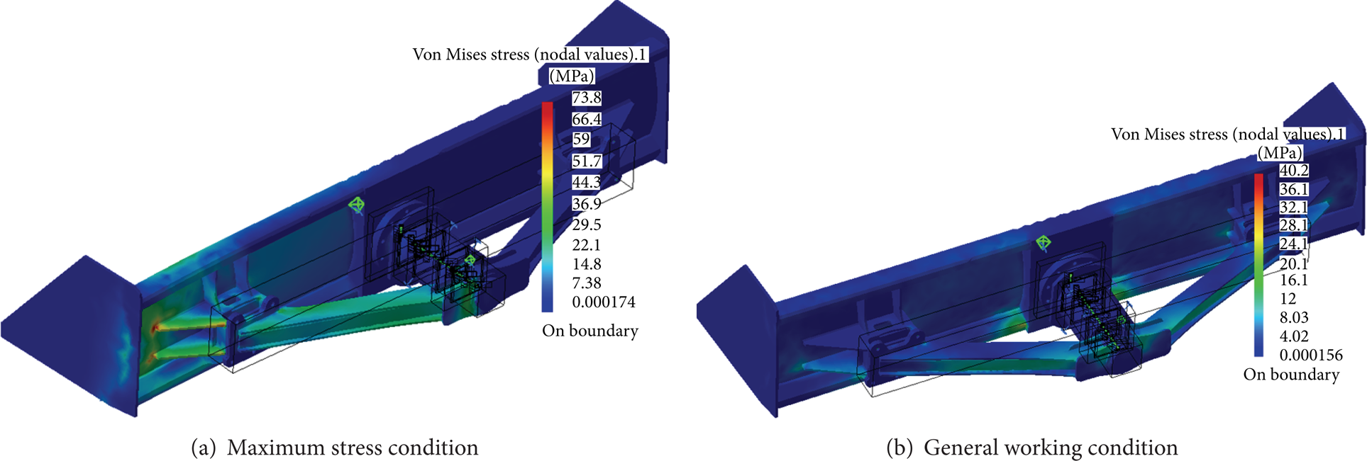
Maximum Von Mises stress on the redesigned shovel.

Displacements and their places on the redesigned shovel.
In the present study, the aim was to examine the usage of drawn steel tube instead of shaft in the construction by using different inner diameter variations while keeping the outer diameter fixed. The required value of the inner diameter of drawn steel tube was also determined according to the results of the assembly structural stress analysis. The maximum stress to be applied onto the assembly system was determined to be one-third of the flow stress of the material. For this purpose, firstly, an assembly structural stress analysis based on the inner diameter of 140 mm was conducted for the maximum stress condition. Then, the analysis was repeated for inner diameters of 120, 100 and 80 mm, and with the inner diameter of 80 mm, one-third of the flow stress of the material has been achieved. Results of the stress analysis conducted for shafts with different inner diameters are given, together with mesh and node numbers, in Table 1. It is obvious that the construction would be in a safer condition in the case of using 160/80 drawn steel tube. The Von Mises stresses and displacement values obtained in relation to these shaft dimensions at maximum stress conditions and general working conditions are given in Figures 17 and 18, respectively.
Stress analysis results for shafts with different inner diameters.


Maximum Von Mises stress usage of drawn steel tube for redesigned shovel.
Displacements and their places usage of drawn steel tube for redesigned shovel.
The results from the analyses of the redesigned shovel are presented in detail in Table 2. As seen in Table 2, maximum stress that is applied to the shovel system at maximum stress condition decreased at the rate of 79% and the maximum displacement decreased at the rate of 90%.
Comparison of main parameters of the initial and redesigned shovel.

The photographic views of production stages of redesigned shovel and the test conditions are shown in Figures 19(a)–19(d).
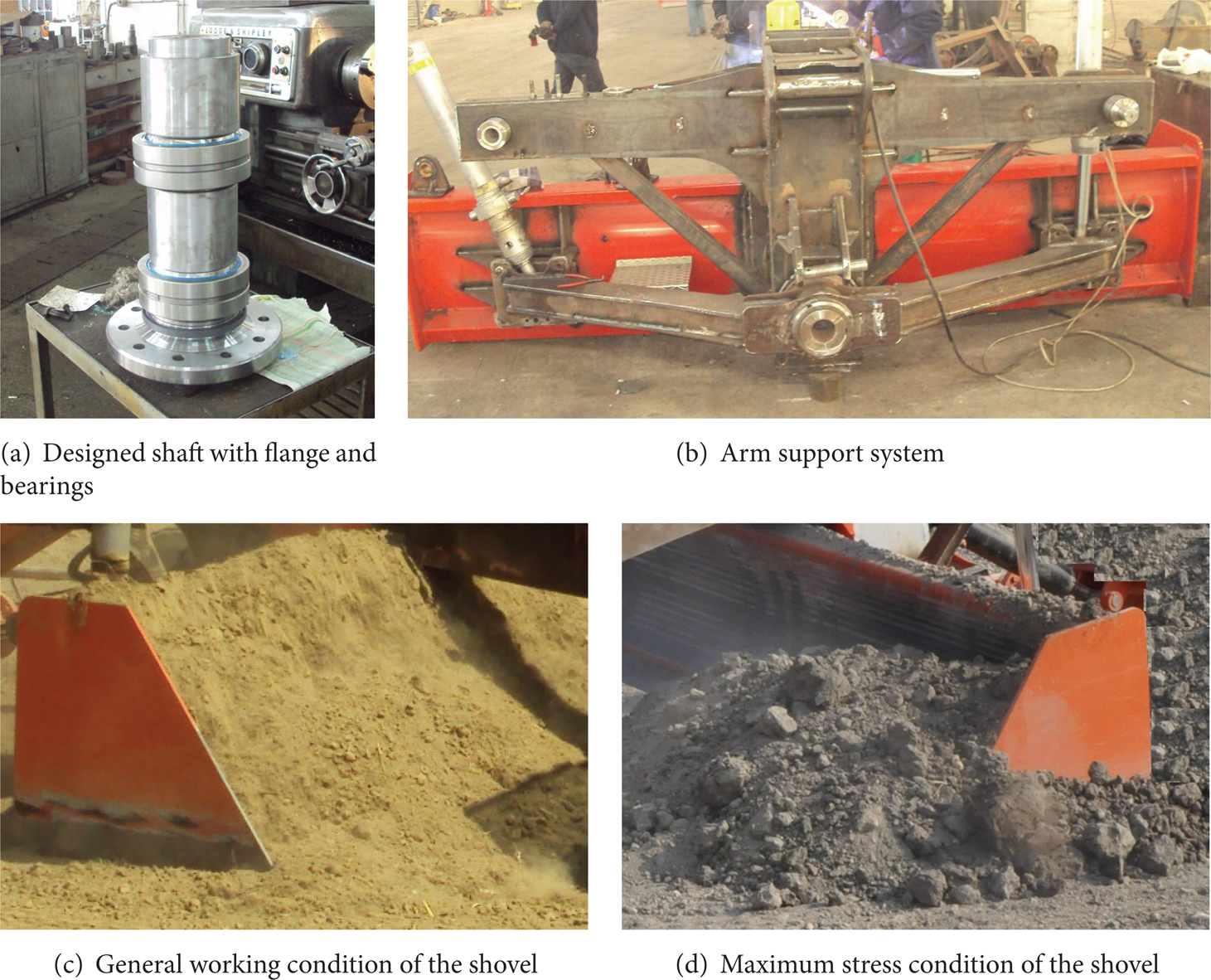
Photographic views of manufacturing stages and working conditions.
4. Conclusion
In this study, the aim was to redesign and manufacture a land levelling shovel, which, in its present condition, is used to get easily damaged even under low loads. Based on the presented results of CATIA obtained for the case of the calculating load acting on the original and redesigned land levelling blade system, the following results are obtained.
Stress analyses of the redesign were conducted through the assembly structural stress analyses by CATIA. Thus, sizing of each of the system elements was reviewed through repeated stress analyses, and the most appropriate geometric dimensions were obtained.
Assembly structural stress analysis using finite element method was successfully carried out to determine high stress value, maximum displacement, and its location on a land levelling blade system.
The maximum stress value on the redesigned system is about 79% lower than the original design of the land levelling blade for maximum stress condition. Thus, the risk of failure is greatly reduced. Besides, the location of the maximum stress has been directed to occur on a relatively easily repairable section of the construction.
Displacements that occur on the shovel were decreased at the rate of 90%, and they are on such a section that poses minimal risk to the construction.
The blade, in the original version, was fixed with respect to the horizontal axis, and in the new design, it has been redesigned and manufactured so as to have the capability of making ± 11° oscillation motion.
Conflict of Interests
The authors declare that there is no conflict of interests regarding the publication of this paper.