
Abstract
Isogeometric analysis (IGA) based on nonuniform rational B-splines (NURBS) is applied for static and free vibration analysis of laminated composite plates by using the third order shear deformation theory (TSDT). TSDT requires C1-continuity of generalized displacements and NURBS basis functions are well-suited for this requirement. Due to the noninterpolatory nature of NURBS basis functions, a penalty method is applied to enforce the essential boundary conditions. The validity and accuracy of the present method are demonstrated through a series of numerical examples of isotropic and laminated composite plates with different shapes, boundary conditions, fiber orientations, lay-up numbers, and so forth. The obtained numerical results are compared with either the analytical solutions or other available numerical methods.
1. Introduction
The requirements for higher stiffness and strength-to-weight ratio, better wear resistance, and greater health characteristics over conventional materials have resulted in the wide application of composite laminates in the area of aerospace, automotive, and underwater structures. Therefore, static and dynamic analysis of both thin and thick laminates becomes an important research topic. Based on different assumptions for displacement fields, several theories for analysis of composite laminates have been developed. The classical plate theory (CPT) relying on the Kirchhoff-Love assumptions [1, 2] can only be applied if plates are thin, because transverse shear deformations are not considered. The first order shear deformation theory (FSDT) which accounts for transverse shear effects [3, 4] can be applied for both moderately thick and thin plates. However, in FSDT, the transverse shear strain is assumed to be constant along the thickness direction, and, thus a shear correction factor (SCF) has to be considered. The SCF depends on many factors, such as material coefficients, stacking scheme, plate geometry and boundary conditions; therefore the evaluation of the SCF remains a subject of research [5]. In addition, with constant shear strain assumption, transverse shear stresses obtained may not be zero on the plate surface, which contradicts the traction free boundary conditions.
To overcome the limitations of FSDT, a more accurate high order shear deformation theory, termed the third order shear deformation theory (TSDT) [6, 7], has been developed to formulate the mechanical behavior of composite laminates. TSDT introduces the cubic variation of the displacement such that more accurate interlaminar stress distributions can be yielded. Therefore, the SCF does not need to be calculated, and the conditions of zero shear stress at both the top and the bottom plate surfaces can be automatically satisfied. However, TSDT requires C1-continuity of generalized displacements, which is not an easy task to achieve using the C0-continuity based finite element method (FEM). To overcome this difficulty, several methods including some mesh-free approaches have been used, for example, the moving least-squares (MLS) method [8], the radial point interpolation method (RPIM) [9], the radial basis function collocation method [10], the finite point formulation with the multiquadric radial basis function method [11], and so forth. In this paper, we demonstrate that such a C1-TSDT formulation can be conveniently achieved by using NURBS-based isogeometric analysis.
Isogeometric analysis (IGA) was first proposed by Hughes and coworkers [12, 13]. The basic idea is that basis functions, usually NURBS basis functions, which accurately represent the geometry are directly used as the interpolation functions of the unknown field variables. Thus, it offers a possibility to close the existing gaps between computer aided design (CAD) and finite element analysis (FEA). Exact geometries are fixed at the coarsest level of discretization and mesh refinement process can be vastly simplified by eliminating the necessity to communicate with the CAD description of the geometry. There are three methods of mesh refinement in IGA, that is, h-refinement of knot insertion, p-refinement of order elevation, and the unique k-refinement of increasing the continuity of basis functions. Therefore, higher order NURBS basis functions with increased interelement continuity can be directly obtained.
Since the pioneer work of Bazilevs and Hughes described above, IGA has been widely applied to various engineering problems including fluid mechanics [14], fluid-structure interaction problems [15, 16], structural shape optimization [17, 18], shell analysis [19–21], linear and nonlinear elasticity and plasticity behavior [22, 23], structural vibration [24], and so forth. In the field of plate analysis employing NURBS-based IGA, Shojaee et al. [25] conducted the analysis of thin composite laminates based on the CPT; Thai et al. [26] performed the analysis of composite laminates using the FSDT; Tran et al. [27] first studied the behavior of functionally graded material plates based on the TSDT. However, numerical examples of these previous researches usually confined themselves into plates with simple shapes and the effects of three plate theories (i.e., CPT, FSDT, and TSDT) on numerical results have not been fully discussed yet.
This paper further develops the NURBS-based isogeometric approach on static and free vibration analysis of composite laminates by using the TSDT. Different from the previous researches, primary focuses are placed on exploring the advantages of the present method in the analysis of plates with complicated shapes. The effects of three plate theories on numerical results are discussed as well.
The remainder of the paper is organized as follows: first, B-Splines, NURBS, and NURBS-based IGA are introduced in Section 2; according to TSDT, an isogeometric formulation for laminated plates is derived in Section 3; Section 4 presents several numerical examples for both static and free vibration analyses of composite laminates with different physical parameters and boundary conditions. Numerical results are compared with analytical solutions and the available data obtained by other numerical methods. Finally, some concluding remarks are given in Section 5.
2. NURBS and NURBS-Based IGA
2.1. Knot Vectors and B-Splines Basis Functions
A knot vector, Ξ, is a set of nondecreasing coordinates in the parametric space

where ξ i ∈ [0, 1] is the ith knot, i is the knot index, i = 1, 2,…, n + p + 1, p is the order of the B-spline, and n is the number of basis functions. A knot vector is said to be open if its first and last knots are repeated (p + 1) times [28]. Open knot vectors are standard in the CAD literature. Unless otherwise stated, open knot vectors are always used in this paper.
With the given knot vector Ξ, B-spline basis functions can be constructed recursively by the Cox-de Boor recursion formula [13]; it starts from p = 0 with
and for p = 1, 2, 3,… they are defined by

2.2. Nonuniform Rational B-Splines (NURBS)
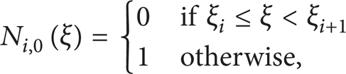
Non-uniform rational B-splines are called NURBS for short. NURBS basis function is given by
which means that every B-spline basis function N i,p (ξ) is set to have a weight ω i [13].
A NURBS curve [13] can be constructed by using (4) in conjunction with the control points
Given two knot vectors Ξ = {ξ1, ξ2,…, ξn + p + 1},

where R i,j p,q (ξ, η) is the tensor product of NURBS basis functions of two parametric dimensions ξ and η,

An example of quadratic NURBS surface with its control points represented by red dots is illustrated in Figure 1.

Quadratic NURBS surface with its control points.
2.3. NURBS-Based IGA
IGA utilizes the concept of isoparametric, which refers to the use of the same basis functions for both geometry and unknown field discretization. The displacements of the control points are the degrees of freedom of the structure. NURBS patch defines a subdomain and knot spans subdivide the subdomain into elements. Mesh refinement strategies are developed from a combination of knot insertion and order elevation, resulting in the h, p or k-refinements as mentioned above. The support of each basis function consists of a small number of elements, depending on the polynomial degree and multiplicity of the knot. Numerical integration is done by Gauss quadrature formulation at the element level.
3. An Isogeometric Formulation for Composite Laminates Based on the TSDT
3.1. The Third Order Shear Deformation Theory
Consider a laminated plate of thickness h shown in Figure 2. The x-y plane is taken to be the midplane of the laminate before deformation, and the kth layer is located between z(k) and z(k + 1) in the thickness direction.

A typical laminated plate and its coordinate system.
The displacement field of a plate based on the TSDT is as follows [7],

where α = 4/(3 h2); (u0, v0, w0) are the displacements of a point on the reference plane in the (x, y, z) directions, respectively; (φ x , φ y ) are the rotations with respect to y and x axis as shown in Figure 2.
While TSDT is applied, five degrees of freedom, u0, v0, w0, φ x , and φ y are considered. Equation (8) can also be expressed in a matrix form as

It can be noted that by setting α = 0, the displacement field based on the first order shear deformation theory (FSDT) can be obtained. Furthermore, by defining α = 0, φ x = − ∂w/∂x, and φ y = − ∂w/∂y, the displacement field based on the classical plate theory (CPT) can be obtained [29].
The pseudostrains with respect to the displacement field are

where β = 3α. Equation (10) can also be stated in a more compact form as

where
The strain-stress relations [30] for an orthotropic lamina in the plate coordinate system (x, y, z) are
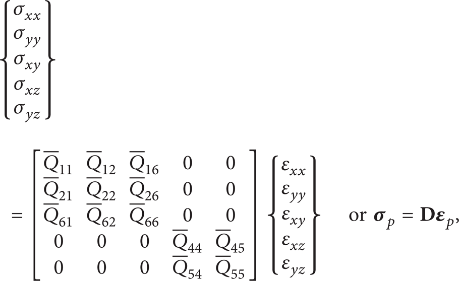
where

All Q ij in (13) are defined in the material coordinate system of the lamina and θ is the angle of fiber orientation. Q ij are given by

where the subscript 1 refers to the fiber direction and subscript 2 refers to the direction transverse to the fiber [30].E1 and E2 are the Young modulus in the 1 and 2 directions, respectively; G12, G23, and G13 are the shear modulus in the 1–2, 2–3, and 3–1 planes, respectively; ν ij are Poisson ratios.
3.2. Penalty Method and Variational Form of System Equations
The boundary conditions for a clamped boundary of a plate can be denoted as follows:

where

Therefore, (15) can be rearranged as

where
The boundary conditions for a simply supported boundary are

Therefore, the differential operator matrix

Since NURBS basis functions do not satisfy the Kronecker-Delta property, special treatments of essential boundary conditions have to be employed using the ideas in meshless method. Available techniques include Lagrange multiplier method [31], penalty method [32], Nitsche's method [33], and others [34]. In this study, penalty method is applied to enforce the essential boundary conditions in both static deflection analysis and free vibration analysis.
Considering the penalty method, the variational form of the equilibrium equation can be expanded as
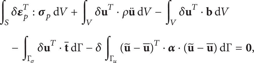
where V and Γ are, respectively, the plate volume and plate surface, (
Substituting (9), (11), (12) and (17) into (20), the variational form of the equilibrium equation can be rewritten as

3.3. Discrete System Equations
Using NURBS basis functions, the displacement field can be interpolated as

where R
I
are the NURBS basis functions and n is total number of them;
Substituting (22) into the variational form (21), the final discrete system equations can be obtained as follows:
where stiffness matrix

where N L denotes the number of layers of the laminated plate. During computation, stiffness and mass matrices should be firstly calculated at each layer and then assembled into system matrix together.

In the static analysis of this paper, only transverse pressure p applied on the plate surface is considered; the global force vector

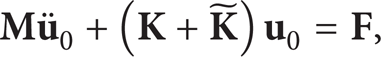
For static analysis, the formulation of a laminated plate can be expressed as

and for free vibration analysis, the formulation can be written as

where ω is the natural frequency.
4. Numerical Examples
In this section, static and free vibration behaviors of both isotropic and laminated composite plates are studied based on the TSDT. Simple square and rectangular plates to more complicated shape plates with various aspect ratios and different boundary conditions are considered. Unless otherwise stated, layers in composite laminates are assumed to have identical thickness and material properties, except that fiber orientations are different. Numerical results are obtained using full (p + 1) × (q + 1) Gauss integration points, where p and q are the orders of the NURBS basis functions in two parametric directions ξ and η, respectively.
4.1. Static Deflection Analysis
4.1.1. Isotropic Elliptical Plate under a Uniform Transverse Pressure
To demonstrate the validity and accuracy of IGA in modeling common engineering shapes, a fully clamped elliptical plate under a uniform transverse pressure is chosen to be analyzed. The lengths of the major and minor axes are assumed to be a = 2 m and b = 1 m; the aspect ratio a/h is taken as 100. A uniform load P = − 1 N is applied. The material of the plate is isotropic with elastic modulus E = 104 MPa and Poisson ratio v = 0.3. Control points and physical meshes of 10 × 10 and 15 × 15 uniform meshed elliptical plates modeled by quadratic NURBS basis functions are shown in Figure 3, respectively.

Control points and physical meshes of (a) 10 × 10 and (b) 15 × 15 uniform meshed elliptical plates.
A series of uniform meshes with quadratic, cubic, and quartic NURBS elements are used in this numerical study. The obtained center displacements are normalized by analytical solutions [35] and the results are plotted against the number of elements per side in Figure 4. It can be seen that the present results converge to the exact solutions. The quartic NURBS elements give sufficiently good results even when the mesh is 10 × 10; however, quadratic NURBS elements suffer from shear locking and cannot get reasonable results on coarse meshes.

Normalized center displacements versus the number of elements per side of a fully clamped elliptical plate.
4.1.2. Four Layers Cross-Ply Square Laminated Plate (0°/90°/90°/0°) under a Sinusoidal Distributed Transverse Load
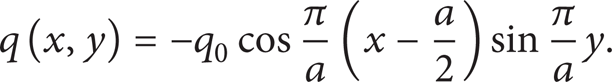
A four-layer cross-ply square laminated plate (0°/90°/90°/0°) under a sinusoidal distributed transverse load q is now considered as shown in Figure 5. The simply supported boundary condition is applied with load q defined as
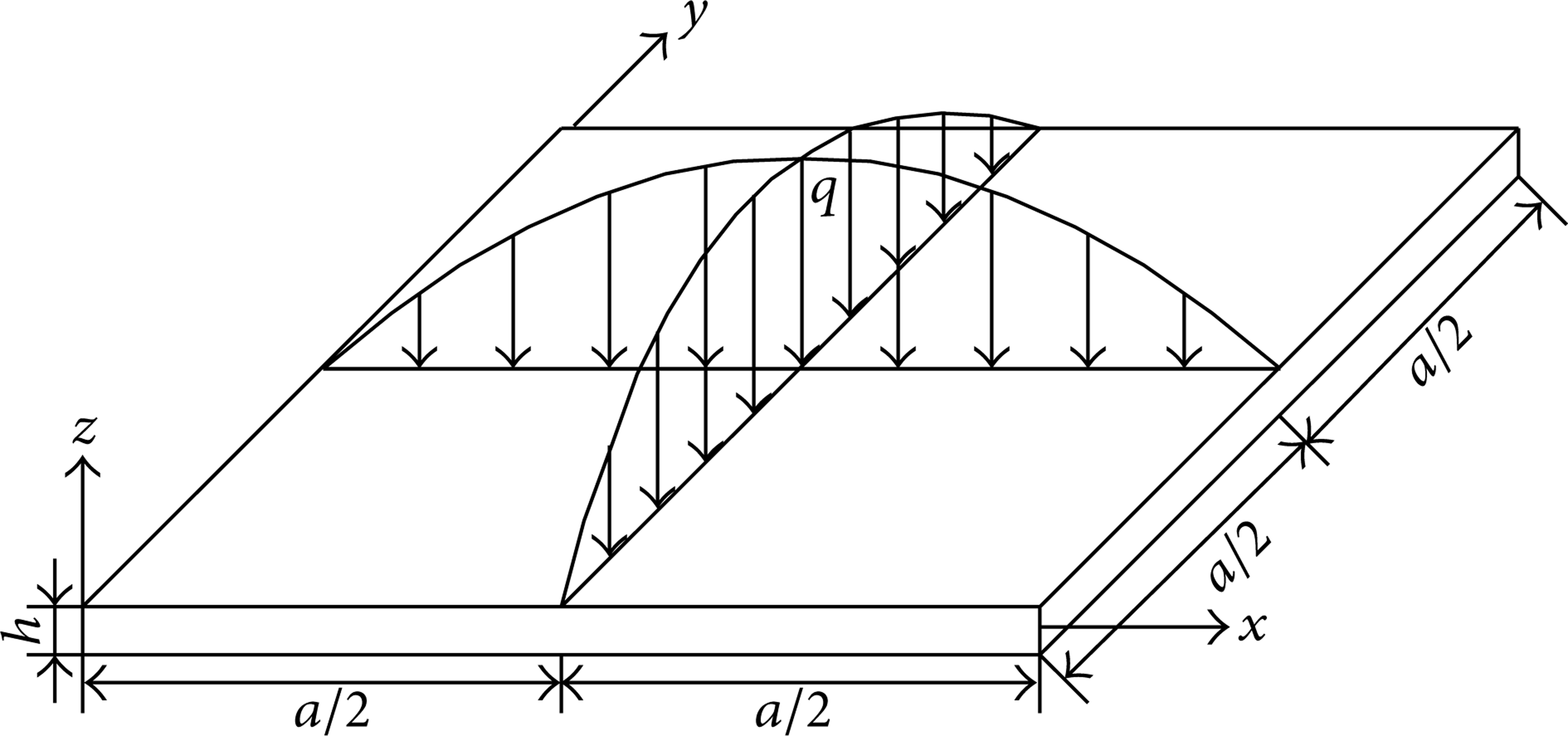
A square laminated plate under a sinusoidal distributed load.
The material properties are given by E1 = 25E2, G12 = G13 = 0.5E2, G23 = 0.2E2, and ν12 = 0.25. By employing the cubic NURBS basis functions, different physical mesh densities are used to study the convergence of the present method. In this numerical study, three densities with 2 × 2, 5 × 5, and 10 × 10 uniform meshes are considered. Physical meshes and control points of the three models are shown in Figure 6. It is clearly evident that geometries can remain precise during h-refinement process. Four plate aspect ratios ranging from 4 to 100, representing thick to relatively thin plates, are employed for simulation. The results of the center deflections are presented using the following nondimensional form for all aspect ratio cases:

Physical meshes and control points of a square plate with (a) 2 × 2 uniform mesh, (b) 5 × 5 uniform mesh, and (c) 10 × 10 uniform mesh.
Nondimensional center deflections obtained by the three given densities of physical meshes are presented in Table 1. In order to compare TSDT with other plate theories, computations based on CPT and FSDT are also conducted on exactly the same mesh employing isogeometric analysis. In addition, other available solutions obtained by mesh-free method of Dai et al. [8], finite point formulation with the multiquadric radial basis function of Ferreira et al. [11], FEM of Reddy [30], and 3D elasticity theory (ELS) of Pagano and Hatfield [36] are also given in Table 1.
Nondimensional center deflections of a square laminated plate under a sinusoidal distributed transverse load.

It can be seen from Table 1 that isogeometric analysis gives solutions that are very agreeable to those of FEM and mesh-free methods. Numerical results can be improved by h-refinement especially when the laminates are thin. The differences of the results between FSDT and ELS get larger when the aspect ratio decreases, for example, when a/h = 100, the result of FSDT is 0.16% smaller than that of ELS; however, when a/h = 4, the relative difference reaches 12.51%, whereas for TSDT, the difference remains very small as 3.09%. This means that FSDT is not suitable for the analysis of thick laminates. It is also noted that the CPT results do not change with aspect ratios, simply because the CPT does not consider thickness effect of laminates. Therefore, just as expected, TSDT is more accurate than FSDT and CPT for not only thin laminates but also thick ones.
In order to investigate the suitability of the present method for the simulation of stresses in composite laminates, stress analysis is conducted in this numerical example. The normalized stresses are given by

By employing cubic NURBS basis functions and 10 × 10 meshes, the normalized stresses of the present method are shown in Table 2. The results of several other methods including the elasticity solution given by Pagano [37], the finite strip method (FSM) based on FSDT by Akhras et al. [38], the finite element method (FEM) based on TSDT proposed by Reddy [7], and the multiquadric radial basis functions (RBFs) method based on TSDT reported by Ferreira et al. [11] are also listed in Table 2. It can be seen that the present solutions agree very well with other published results, especially the numerical results of Reddy [7].
Normalized stresses of a square laminated plate under a sinusoidal distributed transverse load.

4.1.3. Three Layers Square Sandwich Plate under a Uniform Transverse Pressure
A simply supported square sandwich plate [39] subjected to a uniform transverse load q is considered in this numerical example.
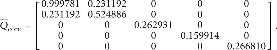
The material properties of the sandwich core are expressed in the stiffness matrix,
Face material properties are related to the core material properties as

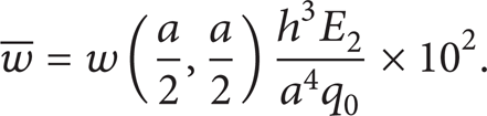
The aspect ratio a/h is taken as 10. A 10 × 10 uniform mesh with cubic NURBS basis functions is used in this numerical study. Normalized displacements and stresses of the square sandwich plates are defined as

where superscript 1, 2, and 3 during the parentheses are layer numbers.
As shown in Table 3, the obtained results with different R values are compared with available solutions by the FEM method of Pandya and Kant [40] and multiquadric radial basis function method (RBF) reported by Ferreira et al. [11]. These two published results are also based on TSDT. In addition, exact solutions of Srinivas [39] are also provided as a reference.
Normalized displacements and stresses of the square sandwich plates.

It can be seen that for all three R values considered, normal stresses σ x and σ y obtained by the present method are in excellent agreement with the exact solutions and the results of the other two numerical methods. As for shear stresses τ xz , the present method can produce reasonable results at location z = 0, which is in layer 2; however, at location z = − 2 h/5, which is the interlamination interface between layers 1 and 2, all these three methods cannot produce accurate results. This is probably due to the discontinuity and the sudden change of material properties at the interlamination interface.
The stress distributions along the thickness of the sandwich plate with R = 15 are plotted in Figure 7 for normal stress component σ x and shear stress component τ xz , respectively. As shown in Figure 7(a), due to the plate being thin, both TSDT and FSDT can predict the normal stress reasonably except that TSDT can get more accurate results than FSDT near the plate surface. Figure 7(b) gives the shear stress distributions and it can be seen that TSDT predicts zero shear stress at both the bottom and the top surfaces, while the results of FSDT remain constant within each layer and are not zero at the plate surfaces, which contradict the real situation.
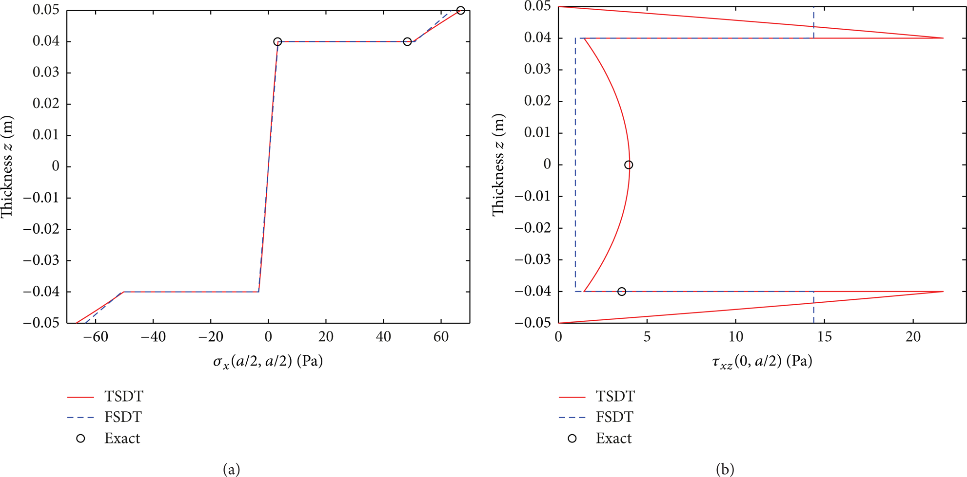
The distribution of (a) normal stress σ x and (b) shear stress τ xz along thickness.
4.2. Natural Frequency Analysis
4.2.1. Clamped L-Shaped Isotropic Plate
A clamped L-shaped isotropic plate with thickness to length ratio h/a = 0.2 and Poisson ratio v = 0.3 is considered in this numerical example [43]. The geometry and NURBS meshes are provided in Figure 8. The natural frequencies are normalized by

where G = E/2(1 + v). In Table 4, nondimensional frequency parameters of the present method are compared with the results obtained by the finite element method using reduced integration Q4 plate elements based on the FSDT by Ferreira [41], the global collocation RBF technique based on TSDT also reported by Ferreira et al. [42], the local RBF finite difference technique based on TSDT provided by Roque et al. [43], and the IGA method based on FSDT given by Thai et al. [26]. It can be seen that with the increase of the order of NURBS elements and the improvement of mesh quality, numerical results of the present method converge to the results of the other published methods. The first four mode shapes of the L-shaped plate obtained by the present method are shown in Figure 9.
Nondimensional frequency parameters of a clamped isotropic L-shaped plate.


(a) Geometry, (b) 10 × 5, (c) 20 × 10, and (d) 30 × 15 NURBS meshes of a clamped L-shaped isotropic plate.

The first four mode shapes of a clamped L-shaped plate.
4.2.2. Isotropic Square Plate with a Complicated Cutout
In order to demonstrate the applicability of isogeometric analysis to exactly represent complicated shapes, natural frequencies are computed for an isotropic square plate with a complicated cutout shown in Figure 10(a). As shown in Figure 10(b), the plate is divided into 8 NURBS patches [31]. The material and geometrical properties of the plate are given by elastic modulus E = 2 × 10¹¹ MPa, Poisson ratio v = 0.3, mass density ρ = 8000 kg/m3, and plate thickness h = 0.05 m.

(a) Geometric parameters (unit: m) and (b) discretization of the patches of an isotropic square plate with a complicated cutout.
With only one element in each patch, the exact geometry can be represented with only eight elements using 28 control points as shown in Figure 11(a). By dividing each patch with 5 × 4 uniform mesh using h-refinement, followed by increasing the order of NURBS basis functions using k-refinement, the refined mesh can be obtained for the numerical study. Figure 11(b) shows the physical mesh and control points of the complicated shape plate modeled by cubic NURBS basis functions.
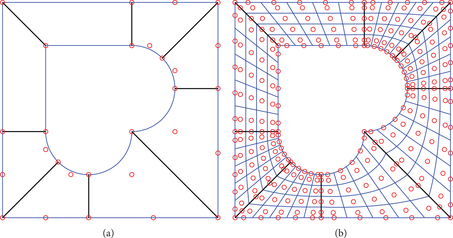
(a) The coarsest mesh and (b) refined mesh of an isotopic square plate with a hole of complicated shape. Blue lines mark the element boundaries, black lines represent the patch boundaries, and red circles are control points.
Natural frequencies are normalized by
Normalized natural frequencies of a simply supported isotropic square plate with a complicated cutout.

Normalized natural frequencies of a clamped isotropic square plate with a complicated cutout.

The first six mode shapes of a simply supported isotropic square plate with a complicated cutout.
4.2.3. Four Layers Cross-Ply Square Laminated Plate (0°/90°/90°/0°) with a Complicated Cutout
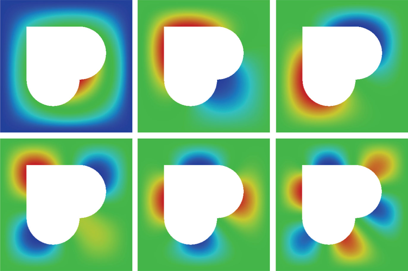
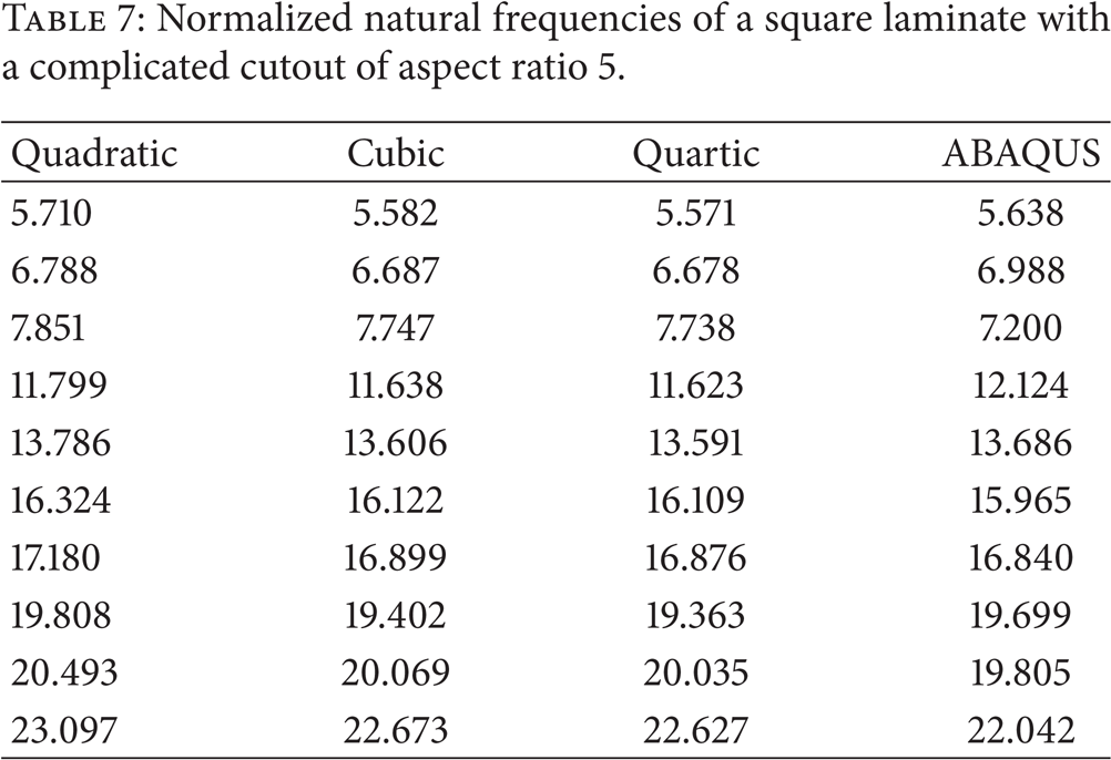
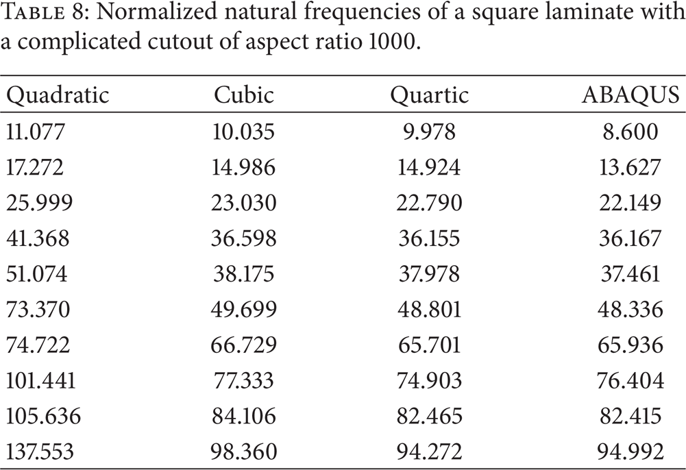
A four-layer cross-ply square laminated plate (0°/90°/90°/0°) with a complicated cutout [47] is analyzed as the last numerical example of this section. The geometry of the plate is shown in Figure 13(a). As shown in Figure 13(b), the plate is divided into 9 NURBS patches. The material properties for all layers of the laminate are identical: E1 = 40E2, G23 = 0.5E2, G13 = G12 = 0.6E2, and ν12 = 0.25. The original coarsest mesh with only nine elements and 34 control points is shown in Figure 14(a). Using the same refinement algorithm as that in Section 4.2.1, Figure 14(b) gives the physical mesh and control points of the refined mesh modeled by quadratic NURBS basis functions. A thick laminated plate with an aspect ratio of 5 and an extremely thin laminated plate with an aspect ratio of 1000 are analyzed, respectively. Only the simply supported boundary condition is considered for simplicity. The first ten normalized natural frequencies are listed in Tables 7 and 8 for the two different aspect ratios, respectively. FEM results obtained by ABAQUS are also provided for comparison.
Normalized natural frequencies of a square laminate with a complicated cutout of aspect ratio 5.
Normalized natural frequencies of a square laminate with a complicated cutout of aspect ratio 1000.

(a) Geometric parameters (Unit: m) and (b) discretization of the patches of a square laminated plate with a complicated cutout.

(a) The coarsest mesh and (b) refined mesh of a square laminated plate with a complicated cutout.
From Tables 7 and 8 it can be seen that isogeometric analysis based on TSDT performs well when the plates are thick, even quadratic NURBS basis functions can get reasonable results; however, when the plates become extremely thin, low order NURBS basis functions suffer from shear locking. When the order increases, numerical results can be improved. The results of quartic NURBS basis functions are in good agreement with those of ABAQUS. The first six mode shapes of a simply supported square laminate with aspect ratio 1000 obtained by the present method are provided in Figure 15.

The first six mode shapes of a simply supported square laminate with aspect ratio 1000.
5. Conclusion
A NURBS-based isogeometric approach has been applied for static and free vibration analysis of laminated composite plates using the third order shear deformation theory. Several isotropic and laminated composite plates with different shapes and boundary conditions are examined for various aspect ratios from thick to extremely thin scenarios. Comparisons are made with the numerical results obtained by other existing methods; isogeometric analysis based on TSDT better matches the actual situation and yields very good results, especially when the plates are thick. One of the advantages of IGA is increasing the order of basis functions without any difficulty. Therefore, high order NURBS basis functions are developed to improve the numerical results especially when the plates are extremely thin. The other advantage of IGA lies in the exact descriptions of complicated geometries. Numerical results of this study demonstrate that the present method is accurate and robust in performing free vibration analyses of plates with complicated shapes.
In the present approach, the phenomenon of shear locking has been noticed and it can be alleviated by mesh refinement. However, the computational cost will be increased due to an excessive increment of control points and the high order of NURBS basis functions. Locking free numerical methods [48–50] and parallel computations [51] are already successfully implemented in isogeometric analysis. Our further studies will focus on their applications in the analysis of beams, plates and shells.
Conflict of Interests
All the authors listed have reviewed the final version of the paper and approved to submit it to this journal. The authors do not have any conflict of interests regarding the content of this paper.