
Abstract
In conventional injection-moulding processes high flow and cooling velocities affect the morphological and tribological properties of microparts when compared to macroscopic parts. A novel mould technology with dynamic CO2-tempering is targeted with an enhanced understanding of the temperature time behaviour of morphology during the setting phase which fundamentally dominates the structure formation. The scope of this paper is to provide an understanding of the processing temperature's influence, in this context mould temperature, on the morphological and tribological properties of injection-moulded microparts. Furthermore, the characteristics of tribological testing conditions in microparts should be identified with regard to optimized testing methods. Results indicate that the tribological properties of microparts are mainly influenced by nature of the skin near layers, which can be greatly improved through the application of mould temperatures close to the crystallisation temperature. Additionally, a tribological testing method is adapted for a correct and high solution of the running-in and stationary phase in order to identify the effects of the skin layer on the wear behaviour.
1. Introduction
Microparts and microsystems technology is reputed as a prospective key technology in industrial applications [1]. Particularly thermoplastic microparts have become more important. The main fields of application for polymer microparts are in the areas of medical technology, as components of optical systems, as microgears in microfluidics, biotechnology, and electronics, or as a micro electro-mechanical system (MEMS) [2, 3].
A reduction of part dimensions causes increasing requirements of the process, Figure 1. Specifically fast cooling rates affect the process and filling behaviour and therefore morphological and mechanical properties of microparts [4, 5]. Former investigations have shown that the fast cooling of small and thin-walled parts made of semicrystalline polymers leads to a fine spherulite structure and lower crystallinity compared to macroscopic parts [6, 7]. This applies in particular to the core layer. The degree of crystallinity and orientation of the skin layer are mainly affected by the shear strain conditions during the filling overlied by cooling [8, 9]. These morphological conditions result in modified mechanical properties [6].
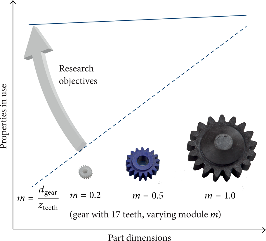
Diagram of a part dimension's influence on properties in use and research objectives of the present work.
Based on the high cooling rates of conventional injection-moulded microparts, adaptions in the process control are carried out in order to increase the injection velocity as well as mould and melt temperature. Another way to influence cooling conditions is through dynamic mould temperature control [10, 11]. This technique allows for a variation of the mould cavity temperature during processing. A temperature above the crystallisation temperature, or rather the melt temperature at the point of polymer injection, enables a facilitative filling of the cavity and a change in the morphology. However, dynamic temperature control may conversely result in increased cycle times. A current topic at the Institute of Polymer Technology is the reduction of cycle time in the dynamic temperature-controlled processing of microparts [12]. The influence of the cooling condition's characteristics on the tribological properties of microparts has yet to be sufficiently investigated.
Tribology is the study of friction and wear, a concept a development engineer may need to take into account for part design and material selection. In sliding rails or machine elements, such as gears or clutches, tribological properties provide a particular challenge [13, 14].
Tribological behaviour cannot be easily predicted. As friction and wear coefficients are dependent not only on the materials employed, but also on the surface topography and load spectrum, for example, they cannot be regarded as material constants. Consequently, tribological behaviour has to be considered within a tribological system [15–17]. A few important parameters within a tribological system are shown in Figure 2. Two basic factors of a tribological system are friction and wear [13].

A tribological system [13].
An evident industrial demand for plastic parts independent of their dimension is their performance optimization with respect to friction and wear behaviour. By varying processing conditions while moulding, the inner properties of the part (e.g., morphology, degree of crystallinity, and orientation), especially of the skin layer, can be significantly affected. Since friction and wear are based on the microcontacts between surfaces, the tribological behaviour is influenced by the locally inner properties of the plastic parts with conventional dimensions [18]. In [19] influences of different morphologies of such thermoplastic parts, induced by processing with varied mould temperatures, on tribological properties have been investigated. The results show that a morphology with distincted spherulites with high crystallinity in the skin near layer shows less wear than finer spherulites with lower crystallinity.
Most microparts, for example microgears and fans, require high strength and wear resistance [20]. Specifically for microparts whose skin near layer morphology is strongly subjected by processing conditions [21] the optimization of the morphology may lead to improved mechanical and tribological properties. Therefore the expanding micro electro-mechanical systems (MEMSs) industry with its high demand for product miniaturization [22] may benefit from further examinations of the morphological and tribological properties of microcomponents.
A propitious way to influence the morphological and tribological properties and the cycle time of microparts is through dynamic temperature control with the possibility of a defined cooling schedule. A new temperature control system which uses CO2 for the heating and cooling of the cavity near tempering channels allows for this defined cooling schedule [23].
2. Materials and Methods
2.1. Dynamic Tempering Concept
Currently several methods for dynamic temperature control are applied in industry. These methods differ in the way in which the temperature control is implemented:
liquid media (oil, water),
electrical resistance heating elements,
induction heaters,
infrared thermal emitters.
Beyond these concepts a new approach for rapid and dynamic temperature control was developed by gwk Gesellschaft Wärme Kältetechnik mbH, Linde AG, and ISK Iserlohner Kunststoff-Technologie GmbH in previous years. This concept is based on the cooling by liquid CO2, also known as CO2 spot cooling [24, 25], in combination with heating with gaseous CO2. It is assumed that this new strategy will take on higher heating and cooling rates with a flexible designing of tempering channels.
Based on the existing knowledge of dimensioning injection-moulding tools to produce microparts and dynamic temperature systems with fluids, a new mould and temperature concept based on dynamic CO2 temperature control has been developed by the Institute of Polymer Technology (LKT) of Friedrich-Alexander-University of Erlangen-Nuernberg in cooperation with quattro-form GmbH and gwk Gesellschaft Wärme Kältetechnik mbH [23].
This dynamic CO2 temperature control should allow the production of microparts with mould temperatures up to 300°C during the injection phase. A subsequent fast-cooling process is achieved with high cooling rates in the cavity areas. In this way the crystallisation process of the material, mainly influenced by thermal process management, is stopped, preferably abruptly. As described in [23], the process is separated into two steps. First, in the heating phase, compressed gaseous CO2 is heated up to 350°C by turbo heaters near the mould and piped through the tempering channels designed by thin, flexible capillary tubes near the cavity. On the ejection and nozzle side integrated temperature sensors adjust the defined mould temperature with the temperature control. This temperature remains constant during the injection and holding pressure phase. Secondly, for cooling, the same tempering system is streamed by liquid CO2 with a pressure of about 60 bar. Due to the expansion of the compressed gaseous CO2 at the end of the capillary tubes, a mixture of snow and gas with a temperature of about −79°C forms. High sublimation energy at the phase transition leads to a high, local cooling effect. After the heat of the mould is dissipated, the gaseous CO2 exhausts through an annular hole between the capillary and the mould.
2.2. Material, Specimens, and Processing
To examine the temperature-dependent correlations between the morphological and tribological properties of the microcomponents, microtensile bars were injection-moulded with an Arburg 370U 700-30/30 injection-moulding machine with a screw diameter of 15 mm. The material used was polyoxymethylene (POM Hostaform C9021, Ticona). The scaling of 1: 16 (total length: 28 mm and thickness: 0.25 mm) of the tensile bar is derived from the Campus tensile bar according to DIN EN ISO 527 type 1 a, Figure 3. To attain better clamping in the tensile tests the total length and both shoulder regions were extended. In particular, the constructive implementation of the temperature control channels required an extension of the specimens.

Dimensions of the 1: 16 scaled tensile bar used in comparison to a standardized tensile bar according to DIN EN ISO 527 type 1 a with the striated section for the tribological test.
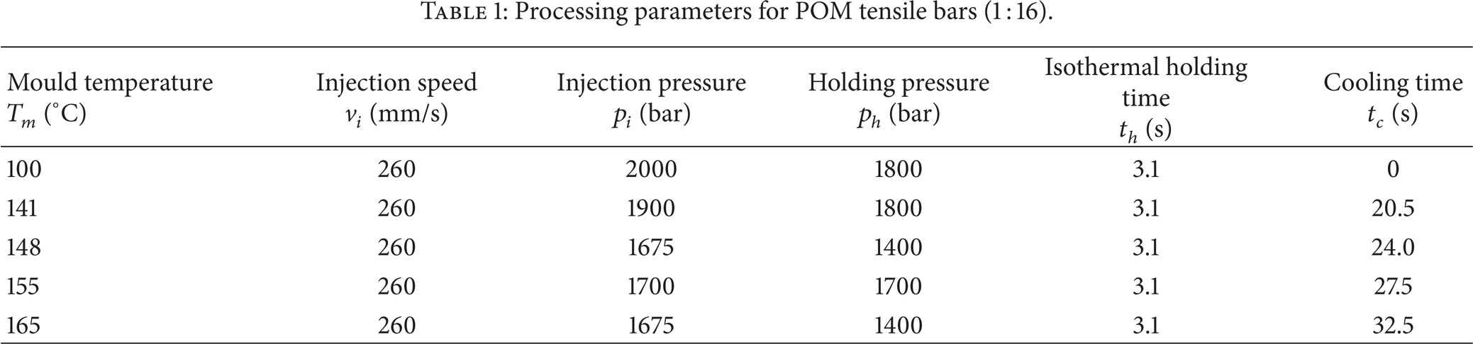
The crystallisation process of the material during processing was influenced by the application of different mould temperatures close to the crystallisation temperature (T c ) area of about 148°C, Figure 4, where the isothermal crystallisation is completed after 66 s. The melt temperature was 230°C for all experiments. The variation of mould temperatures help identify the morphological, mechanical, and tribological changes induced by different conditions of crossing the crystallisation temperature. To compare the influence of such high mould temperatures with conventional conditions, a mould temperature of 100°C was additionally used. Table 1 shows the main processing parameters.
Processing parameters for POM tensile bars (1: 16).
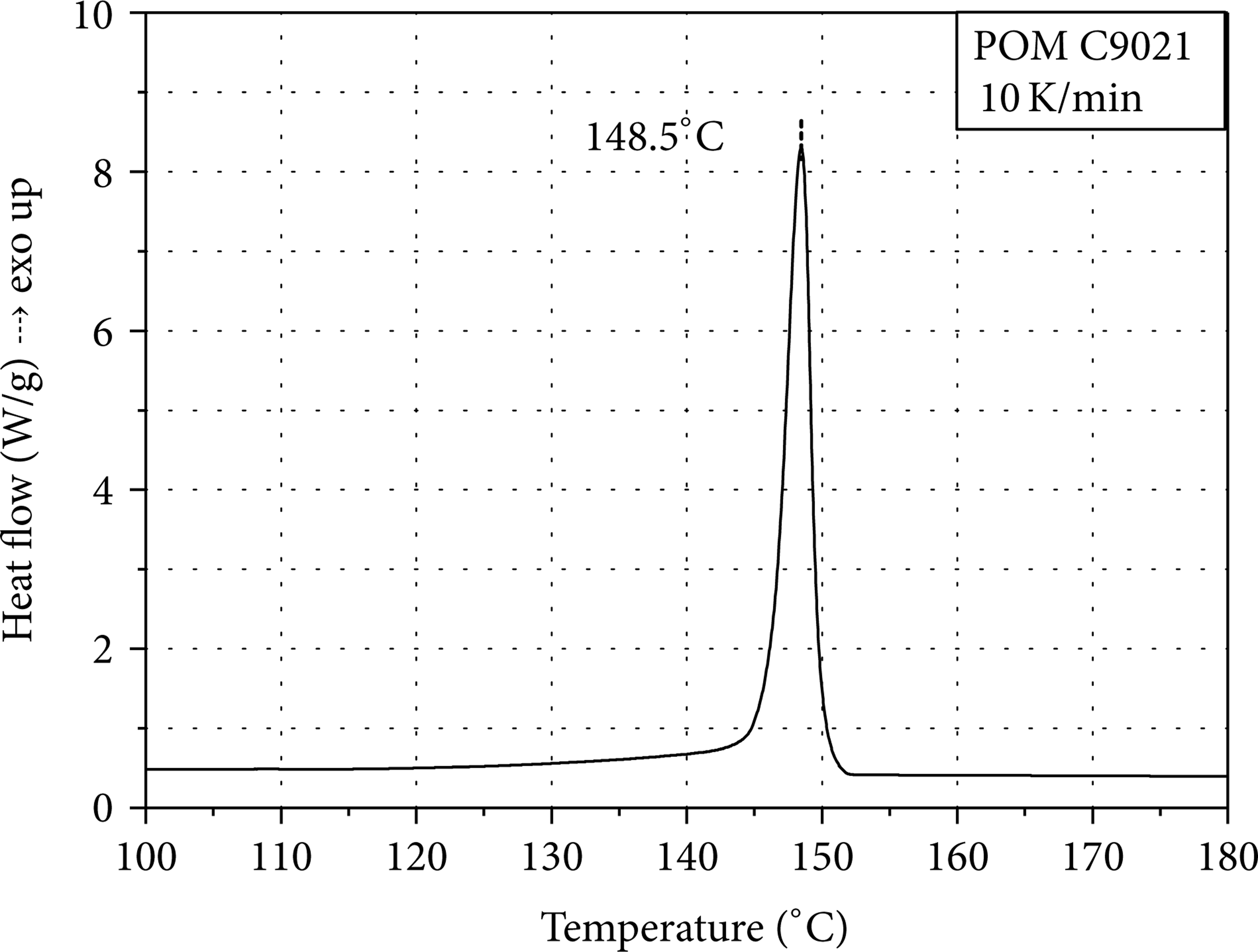
Heat flow with respect to the temperature measured by DSC.
The temperature distribution and time-dependent behaviour of the mould temperature were measured in preliminary tests where temperature sensors were placed in the cavity of the open mould. The variation in temperature equaled ± 2°C.
After the mould is closed and the adjusted mould temperature (T m ) is reached, the material is injected with a defined injection (p i ) and holding pressure (p h ). The switchover to holding pressure is pressure-controlled. A typical injection time is 0.5 s. During the injection and holding phase, which amounts to 3.1 s, the mould temperature was held isothermally (t h ). Afterwards, liquid CO2 is introduced for cooling (t c ) until the adjusted ejection temperature of 100°C (T e ) is reached and the microparts can be demoulded, Figure 5. The cooling rate is 2 K/s.

Diagram of mould temperature variations during the injection-moulding process (T m : mould temperature; Tmelt: melt temperature; T e : ejection temperature; T C : crystallisation temperature; t i : injection time; t h : holding time; t c : cooling time).
2.3. Analysis
2.3.1. Morphology
The semicrystalline morphology in the cross-section of the microtensile bars was inspected with 10 μm-thick cuts by polarised light microscopy at under 45°. The thin cuts were taken from the middle of the tensile bar along the direction of injection.
2.3.2. Pin-on-Disc Wear Testing
The tribological tests were conducted with a pin-on-disc test; a schematic setup is shown in Figure 6. The plastic pin (10 mm × 0.25 mm × 0.625 mm) is cut out of the tensile bar (striated section Figure 3) and pressed against a rotating steel disc. The rotational speed of the disc and thus the sliding speed v of the interface to the pin, as well as the applied force and the corresponding pressure p, are the setting parameters (v = 0.5 m/s; p = 4 N/mm2). The ambient temperature T is held at a constant 23°C, and the tribological contact is kept in a technically dry state.

Pin-on-disc test.
While the disc is rotating, the pin wears and its decreasing length x is measured by a displacement transducer. The friction force F R is measured by a load cell which detects the transverse force exerted onto the pin by the rotating disc and the applied normal force F N . The sample size is at least three.
The investigation of the tribological properties considers various aspects. As a first step of evaluation the running-in and stationary phases are analysed. The running-in phase respresents the conditions of the beginning of the test, indicating that a correlation with the surface morphology of the material is possible. This phase is assumed to provide stronger effects for the existing cooling conditions. During the quasistationary section of the running-in phase, the coefficient of wear as a function of wear volume, normal force, and wear path is determined (see (1)).
Consider

The analysis of the coefficient of wear during the stationary phase k s , see Figure 7, enables conclusions about the morphologically based wear behaviour in the core area to be drawn.
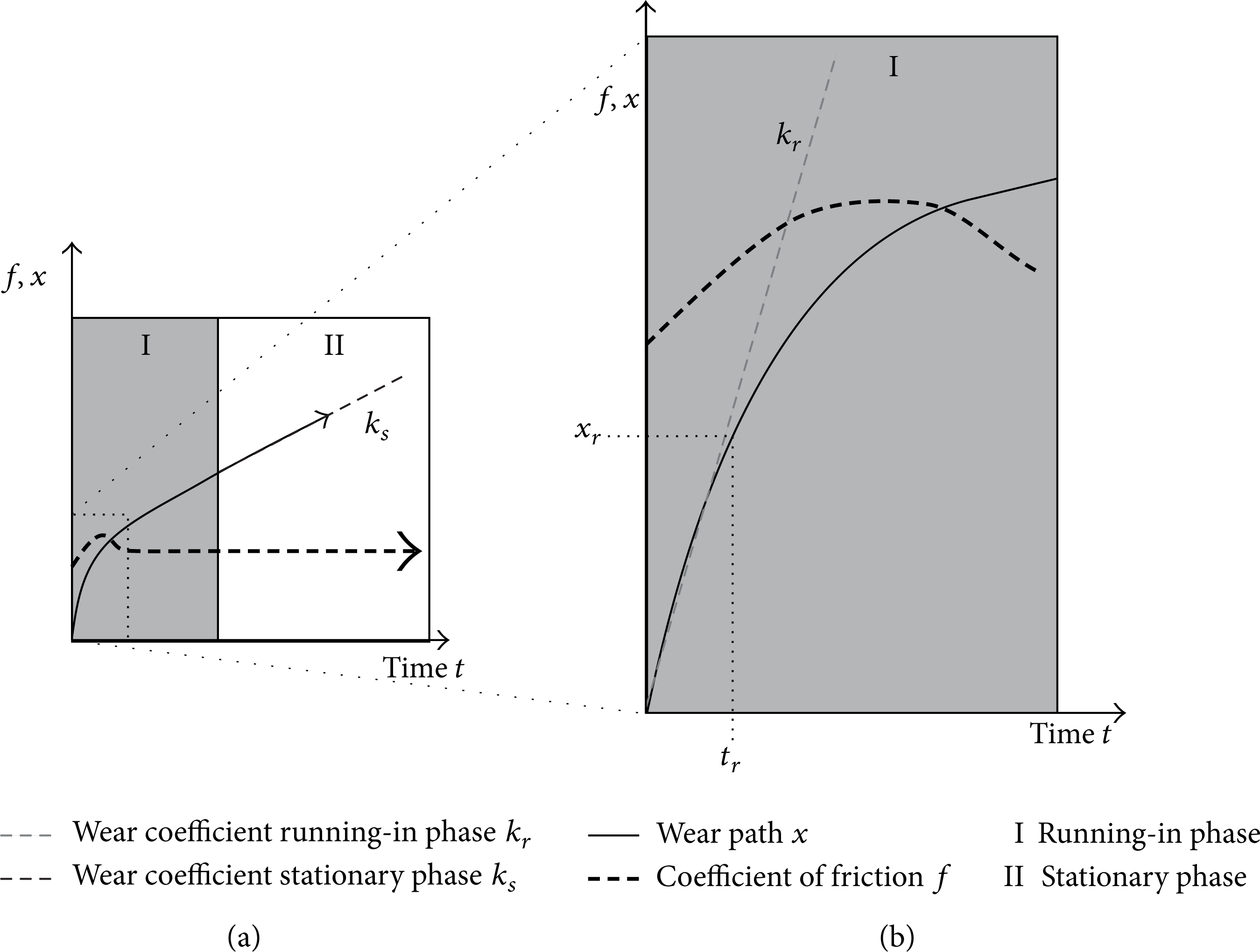
Coefficient of friction and wear throughout running-in and stationary phases (a) and throughout the running-in phase (b) [19].
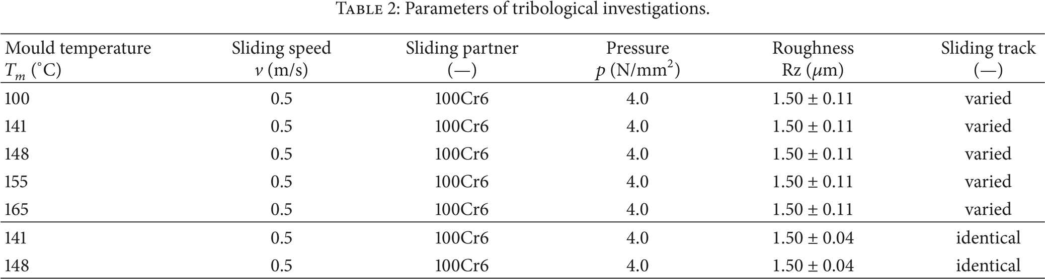
As a second step the sliding partner's topographical influence, which is represented by the deviation of the sliding track's roughness, was analysed, Table 2. In order to represent the industrial manufacturing variations in metal surface processing, varied sliding tracks were used for each test. The mean roughness Rz selected is 1.50 μm with a deviation roughness of 0.11 μm between the different sliding tracks. This value for Rz is typical for industrially treated steal surfaces, allows for a transfer to industrial applications [19], and was uniformally employed in the present study. In order to accurately analyse the effect of a changing topography on the wear, tests are carried out using an identical sliding track for each individual test with a roughness Rz of 1.50 μm and a deviation of only 0.04 μm. Tests are carried out on specimens produced at mould temperatures of 141°C and 148°C. All other parameters remain the same. To obviate possible material transfer, the pin and disc were cleaned before each test with isopropanol and acetone. This procedure also verifies whether the variation of surface topography can be reduced for structure-property relationships to become more evident.
Parameters of tribological investigations.
2.3.3. Mechanical Testing
To determine the mechanical behaviour of the scaled tensile bar, tensile tests according to ISO 527-1 (standard climate 23°C/50% rel. humidity) were performed using the tensile testing machine MicroTester 5948 (Instron Deutschland GmbH). The velocities for the tensile modulus and yield stress were also adapted to the scaled tensile bar.
3. Results and Discussion
3.1. Morphological Structure
The morphological structure over the cross-section of the 1: 16 tensile bars with respect to the mould temperature is shown in Figure 8. At a mould temperature of 100°C a multilayer structure is evident. This structure differs significantly from the morphologies of parts produced with mould temperatures of 141°C to 165°C. A mould temperature of 100°C and a melt temperature of 230°C result in a high cooling rate of the skin near layers and a distinct temperature gradient over the cross-section. Therefore, a different local crystallization behaviour is induced. For the thermal nucleation, the maximum of the nucleation rate lies at lower temperatures than the maximum of the growing rate [26]. This means that a slow cooling rate is accompanied by a high growing rate of few nucleuses and eventually a coarse spherulitic structure. Regarding the mechanical properties, coarse spherulites cause low yield strength and tensile stress at break [27]. Moreover, it is a well-known fact that an increasing cooling rate leads to lower degrees of crystallinity in semicrystalline thermoplastics. Lower degrees of crystallinity cause lower modulus and yield stress [27]. The degree of frozen orientations is also influenced by cooling. With cooling rate increasing, the relaxation of orientations is hindered.
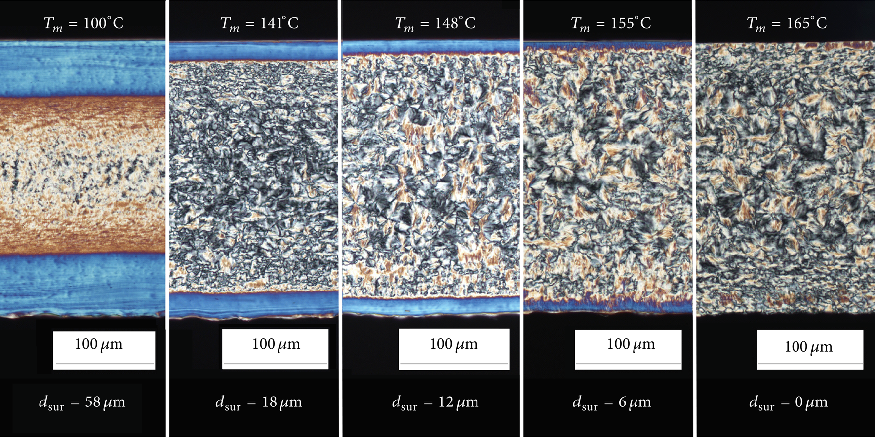
The morphology of different POM microtensile bars with respect to mould temperature (polarized light microscopy of 10 μm thin cuts).
Therefore, a mould temperature of 100°C leads to a wide and distinct orientation of the skin layer, which can be explained by high shear strain rates and high cooling velocities shown in frozen oriented macromolecules. The transition region between the surface and core is characterised by a microcrystalline slightly orientated layer resulting from lower shear strain rates combined with a decreasing cooling rate. In the small core a fine crystalline structure with small spherulites is observable due to low shear strain rates and moderate cooling conditions.
Increasing the mould temperature in conjunction with a reduction of the cooling rate leads to a decreased thickness of the oriented skin layer (dsur) from about 60 μm at 100°C to nearly 0 μm at 165°C. This can be explained by decreasing shear strain rates in the skin region due to a decreasing melt viscosity with rising temperature as well as a longer relaxation time of oriented macromolecules due to lower cooling rates. Furthermore, the transition region is defined by a small spherulitic structure with less orientation and thickness at higher mould temperatures as explained above. In the core, a mould temperature of 141°C and above leads to a rough spherulitic structure with a more homogenous spherulite size distribution attributed to a slow cooling.
In summary, a mould temperature in the range of the material's crystallisation temperature leads to a reduction in the thickness of the distinctly orientated skin layer. Further, due to the long-term higher temperatures major relaxations in flow-induced orientations near the skin and a propitious crystallisation, resulting in a more homogeneous, rough spherulite morphology over the cross-section, can be identified.
3.2. Mechanical Behaviour
The tensile modulus and yield stress of microtensile bars according to the mould temperatures are shown in Figure 9. The tensile modulus and the yield stress at 100°C and 141°C are slightly higher than at higher temperatures of 148°C, 155°C, and 165°C. The mechanical parameters represent an integrated result over the cross-section of microtensile bars. Therefore, the higher characteristics of the lower mould temperature can result from the distinctly orientated skin layer. Further studies of layer-affected investigations should provide information about the mechanical characteristics of different layers according to varying mould temperatures.

Tensile modulus E and yield stress σ y of microtensile bars with respect to mould temperature T m .
3.3. Tribological Behaviour
In Figure 10 the wear coefficient k r and the wear path x r of the running-in phase are shown with respect to varying mould temperatures. At a mould temperature of 100°C the wear coefficient reached 68 × 10−6 mm³/Nm. At higher mould temperatures the wear coefficient ranged between 23 and 35 × 10−6 mm³/Nm. The experiments with specimens produced at a mould temperature of 100°C had the highest wear path at 51 μm. The experiments with specimens produced at a mould temperature close to T c had significant lower wear paths between 21 and 24 μm.

Wear coefficient k r and wear path x r during the running-in phase with respect to mould temperature.
Thus, the specimens produced at a mould temperature of 100°C reached the highest wear coefficient and wear path. The results of the specimens produced at a mould temperature of 141°C and above showed significantly lower values for k r and x r . The correlation of the wear coefficients and the morphological structure shows that the wear path of parts produced at a mould temperature of 100°C and 141°C equates well with the thickness of the oriented skin layer, while these of parts produced at higher temperatures are the resulting sum of the skin layer and transition region to the core. Therefore, an optical assessment by microscopic methods is not entirely sufficient. At the current state of research, it can be assumed that the distribution of the degree of crystallisation from skin to core is responsible for wear of microparts. The proof of this assumption should be done by an analysis of the layer-dependent degree of crystallisation in further investigations.
The difference in wear coefficients between the running-in phase k r (skin layer) and the stationary phase k s (core area) with respect to varying mould temperatures is shown in Figure 11.

Wear coefficient of the running-in phase k r and the stationary phase k s with respect to mould temperature.
The wear coefficient k r is again represented for better comparability purposes. While the mean values of k r ranged from 68 × 10−6 mm³/Nm for specimens produced at a mould temperature of 100°C to 23 and 35 × 10−6 mm³/Nm for specimens produced at higher mould temperatures (close to T c ), the values of k s are significantly lower, between 5 and 7 × 10⁻⁶ mm³/Nm. In comparison to k r , no significant influence of the mould temperature can be observed for k s . Again this may be attributed to the morphological structure. In the core area of the specimens, where k s is measured, the different specimens show a more homogeneous spherulitic structure; see Figure 8. Furthermore, the degree of crystallisation in the core at about 74% was similar for all parts [23]. This leads to the assumption that the distinct spherulitic structure with a high degree of crystallisation in the core of the specimens shows less wear than the skin layer and the fine spherulitic structure.
To investigate the influence of opposing sliding partner's different topographies on wear, wear tests were also performed on the identical sliding track of the same steel disc. By excluding the effect of topographical variations, this ensures the examination of the relationships between the structure and properties of the specimens tested, especially in the skin near layers. The results are shown in Figure 12.

Comparison of the parameters wear coefficient k r and wear path x r during the running-in phase with respect to the topographical variations in the sliding partner.
The wear coefficient and wear path of the tests using the identical sliding track show comparable values to those using varied sliding tracks. As assumed, the standard deviations for the parts tested with an identical sliding track are significantly smaller. Thereby, a slight decrease in the wear coefficient of parts produced at a mould temperature of 141°C (k r = 26 × 10−6 mm³/Nm) compared to those produced at 148°C (k r = 21 × 10−6 mm³/Nm) can be recognized. This may be attributed to slightly different morphological changes in the skin near layers. Parts produced at a mould temperature of 141°C have a slightly thicker skin layer than parts produced with 148°C. Conclusively, by using the same sliding track, the influence of topographical effects can be reduced and therefore structure-property relationships can be better observed with tribological testing.
4. Conclusion
The present work describes a novel mould technology with dynamic CO2-tempering for the establishment of a more thorough understanding of the temperature-time behaviour in the morphology of microparts during the setting phase. This is attributed to a defining structure formation and therefore affects the tribological behaviour. A highly oriented skin layer and the distinct formation of a transition region to the core, resulting from microparts produced at a constant, low mould temperature of 100°C, leads to greater wear. The employment of mould temperatures in the range of the utilized POM and beyond said temperature, results in a quantifiably defined reduction in the thickness of the skin layer as well as the transition region to the core, what leads to a significant reduction in wear. A correlation between the distribution of the degree of crystallinity in the cross-section of parts with tribological effects should be further investigated in future research.
Moreover, the investigation into the characteristics of tribological testing conditions in microparts indicates that the examination of the running-in phase is the morphologically defining part that is dependent upon the processing temperature.
Undesirable deviations in wear properties due to topography effects can be reduced by minimising the surface effects of the sliding partner, for example, through utilisation of an identical sliding track. As such, the structure-property relationships in the skin layer and transition region, which are predominately important for the micropart's properties, can be discernibly observed during tribological testing.
Conflict of Interests
The authors declare that there is no conflict of interests regarding the publication of this paper.
Footnotes
Acknowledgments
The authors would like to thank the Deutsche Forschungsgemeinschaft (DFG) for funding the work in the Project DR 421/9-1. Furthermore, they acknowledge the support by Deutsche Forschungsgemeinschaft and Friedrich-Alexander-Universität of Erlangen-Nürnberg within the funding programme Open Access Publishing. The authors also extend their gratitude to their industrial partners quattro-form GmbH for supporting the mould design, Linde AG and gwk Gesellschaft Wärme Kältetechnik mbH for providing the dynamic CO2-tempering equipment, and Celanese Corporation for providing the material.