
Abstract
An investigation on the stability of hypersonic boundary layer over a cone at small angle of attack has been performed. After obtaining the steady base flow, linear stability theory (LST) analysis has been made with local parallel assumption. The growth rates of the first mode and second mode waves at different streamwise locations and different azimuthal angles are obtained. The results show that the boundary layer stability was greatly influenced by small angles of attack. The maximum growth rate of the most unstable wave on the leeward is larger than that on the windward. Moreover, dominating second mode wave starts earlier on the leeward than that on the windward. The LST result also shows that there is a “valley” region around 120°~150° meridian in the maximum growth rates curve.
1. Introduction
Laminar-turbulent boundary layer transition has dramatic effects on hypersonic vehicles, such as reentry vehicles and hypersonic cruise vehicles. These effects include heat transfer, skin friction, and separation which can hinder the thermal protection of the vehicles; even angle of attack effects can change flight instability [1]. Therefore, it is of importance for vehicle designers to understand the laminar-turbulent transition phenomena and transition mechanism. Circular cone is a simple and prototypical geometry of hypersonic vehicles. The boundary layer transition on circular cone is influenced by Mach number, Reynolds number, roughness, bluntness, angle of attack, pressure gradient, temperature, and so forth. Because of almost all the circular conical vehicles cruising at a certain angle of attack (AoA), much research of AoA effects has been made on hypersonic boundary layer transition and instability.
A series of ground wind tunnel experiments have been conducted to investigate the AoA effect on supersonic/hypersonic boundary layer transition on a cone since 1960s [2–8]. These experimental data showed that the transition location was very sensitive to the small AoA. For small AoA with small bluntness, the transition position shifts upstream on the windward ray and downstream on the leeward ray, relative to the zero-deg AoA. Although these results provided the transition location, no improved knowledge of the phenomena responsible for this trend was obtained. The transition mechanism is still poorly understood, so a detailed investigation should be made if we want to know this transition mechanism.
Stability experiment is a vital method to understand that the mechanism leads to transition and turbulence. Only two stability measurements on a circular cone have been conducted at small AoA up to now. Stetson et al. [9] measured detailed boundary layer profiles and laminar instability on a 7° half-angle sharp cone at Mach 8. Profiles were measured on the windward and leeward meridians. Instability-wave amplification was deduced from spectral measurements. The data showed that the critical Reynolds number increased on the windward meridian and appeared to decrease on the leeward meridian. First mode disturbance growth was reduced on the windward ray, while second mode amplification was not greatly affected by AoA. Doggett et al. [10] used hot-wire anemometry diagnostics to identify the boundary layer instability mechanisms which lead to transition. The experiment was carried out on a flared-cone model in the low-disturbance Mach 6 quiet wind tunnel at NASA Langley Center. This is the first hypersonic stability measurement under low noise conditions. The second mode instability was stabled at windward ray at 2° AoA relative to zero-deg AoA that indicate the small AoA can stabilize the windward ray boundary layer; however, on the leeward the very high frequency of the dominant instability was higher than the estimated frequency of the second mode disturbances; thus Doggett thought that this mechanism which dominated the instability and transition on the leeward was different from the normal second mode. No literature mentioned what mechanism it was.
Small AoA has two aspects on hypersonic boundary layer of a cone relative to zero AoA. First, it changes the thickness of boundary layer and the velocity profile; the thickness of boundary layer will be thinner on the windward and thicker on the leeward, so it changes the streamline instability. Second, the pressure gradient that exists around the cone creates a component of velocity perpendicular to the edge streamwise velocity called crossflow. This crossflow component causes new inviscid instability-crossflow instability. Schneider [11] made a detailed summary from both experiment and computation sight on AoA effects on sharp cone and blunt cone. He pointed out that transition on circular cone is very sensitive to small AoA, especially for slender cones with smaller nose radius. This is presumably due to crossflow, which carries low-momentum fluid from the windward to the leeward sides. Moreover, Schneider [12] also carried out an experiment on a cone in Purdue Mach 6 Tunnel. In this experiment, temperature sensitive paint and oil-flow technique were used to visualize crossflow vortices, and oil-flow images give the development of crossflow on a sharp cone at AoA.
Besides experimental research, some stability computations have been made on hypersonic boundary layer stability over circular cones. Simen et al. [13] made detailed computations for Stetson's sharp cone at AoA. The computed amplification growth on the leeward ray showed good agreement with experimental measurement. Hanifi et al. [14] calculated the boundary layer stability on a sharp cone at 1° AoA at Mach number 5. The results revealed that the most unstable second mode wave shifts from 2D to oblique and the first mode amplification rates change by 40%. Recently, Balakumar and Owens [15] investigated stability, transition onset, and generation of crossflow vortices in a three-dimensional hypersonic boundary layer over a sharp-tipped, 7° half-angle cone at an angle of attack 6.0° using a weighed essentially nonoscillatory (WENO) scheme. Stability results show that azimuthal wavenumbers are in the range of m∼20–50 for the most amplified traveling disturbances and in the ranges from m∼30 to 70 for the stationary disturbances. The simulations also show the crossflow vortices originating from the nose region propagate towards the leeward ray. Gronvall et al. [16] also carried out a simulation of transition process of this cone model; surface roughness was used for this work in order to investigate its effect on the crossflow instability; it gave the obvious difference of streak angle of inclination between the calculation and experiment.
The main objective of the present research is to study the instability mechanisms of boundary layer over a cone at small angle of attack at Mach 6.0. After obtaining the steady flow, the stability characteristic at different stations was calculated by LST. The growth rates of the second mode and first mode waves at different azimuthal angle were obtained at the streamwise location of X/R n = 100.7, 200.9, and 301.2. The stability characteristic at azimuthal angle around 150° is focused. These results are presented in this paper.
2. Steady Flow over a Cone
The undisturbed steady flow solutions over a cone without any free stream disturbances are obtained by NND finite difference scheme with second order accuracy [17] in advance. Table 1 gives the computational conditions and flow parameters. Figure 1 gives the numerical grids for the cone computation. In order to get an accurate solution, the grid points are clustered near the nose and the wall. The size of grid is chosen as 151 (streamwise) × 31 (circumferential) × 201 (normal) based on the verification of grid dependence. On the wall of cone body, no-slip and isothermal conditions are assumed.
Computational conditions and flow parameters for steady flow.


Grids of the cone for steady flow and azimuthal angle definition.
Figure 2 gives comparison of velocity profile distribution in the wall normal direction at the location of X/R n = 200.9 (Re x = 2.0E + 6) for different azimuthal angles. Figure 3 gives comparison of the displacement thicknesses. It can be seen that small AoA changes velocity profile and displacement thickness a lot. The displacement thickness of boundary layer in the leeward ray is much thicker than that in the windward ray. It is noticed that around 150° azimuthal angle there is an abrupt increase in the displacement thicknesses curve especially at AoA of 2°.
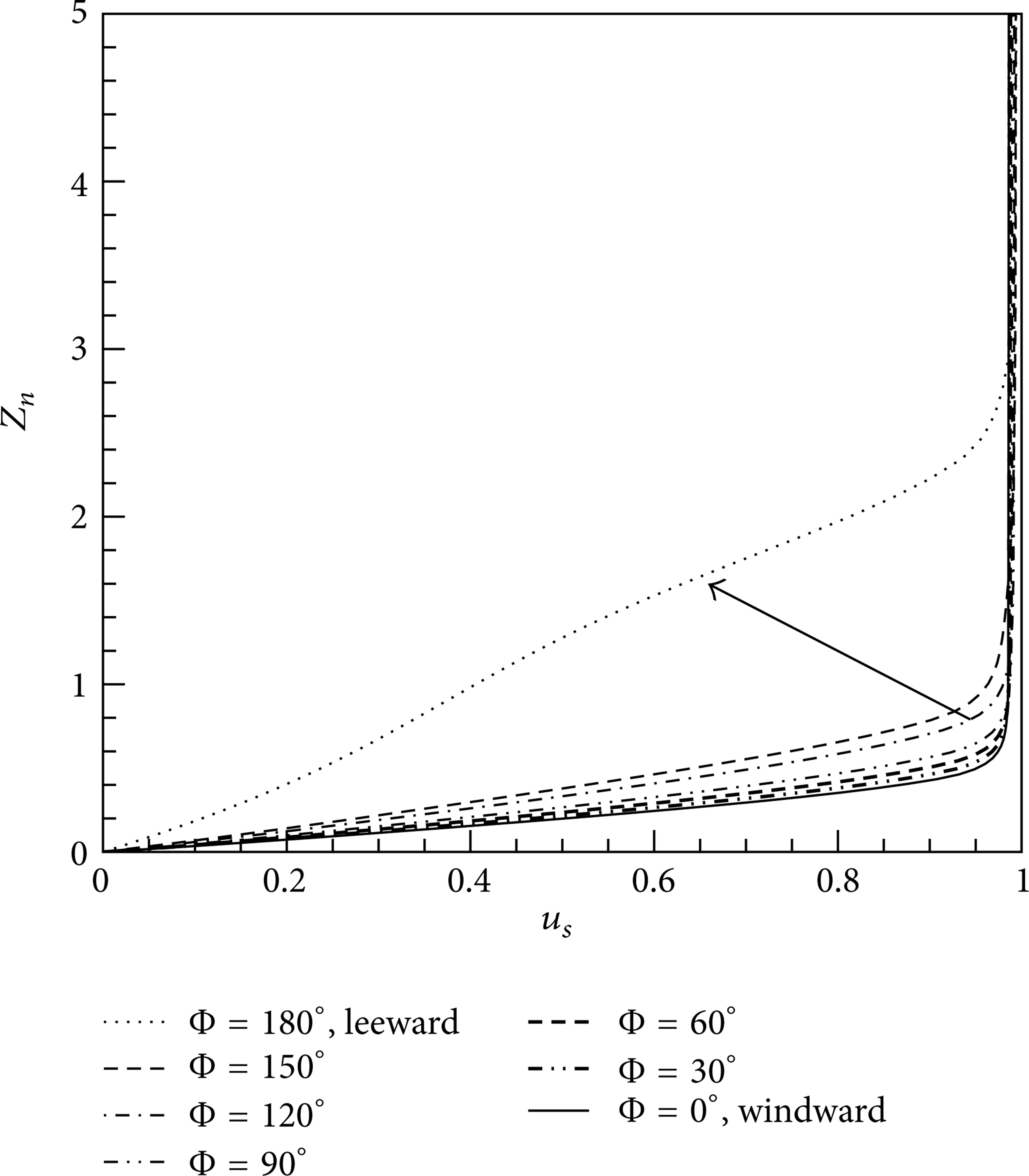
Comparison of streamwise velocity profile, AoA = 2 deg.
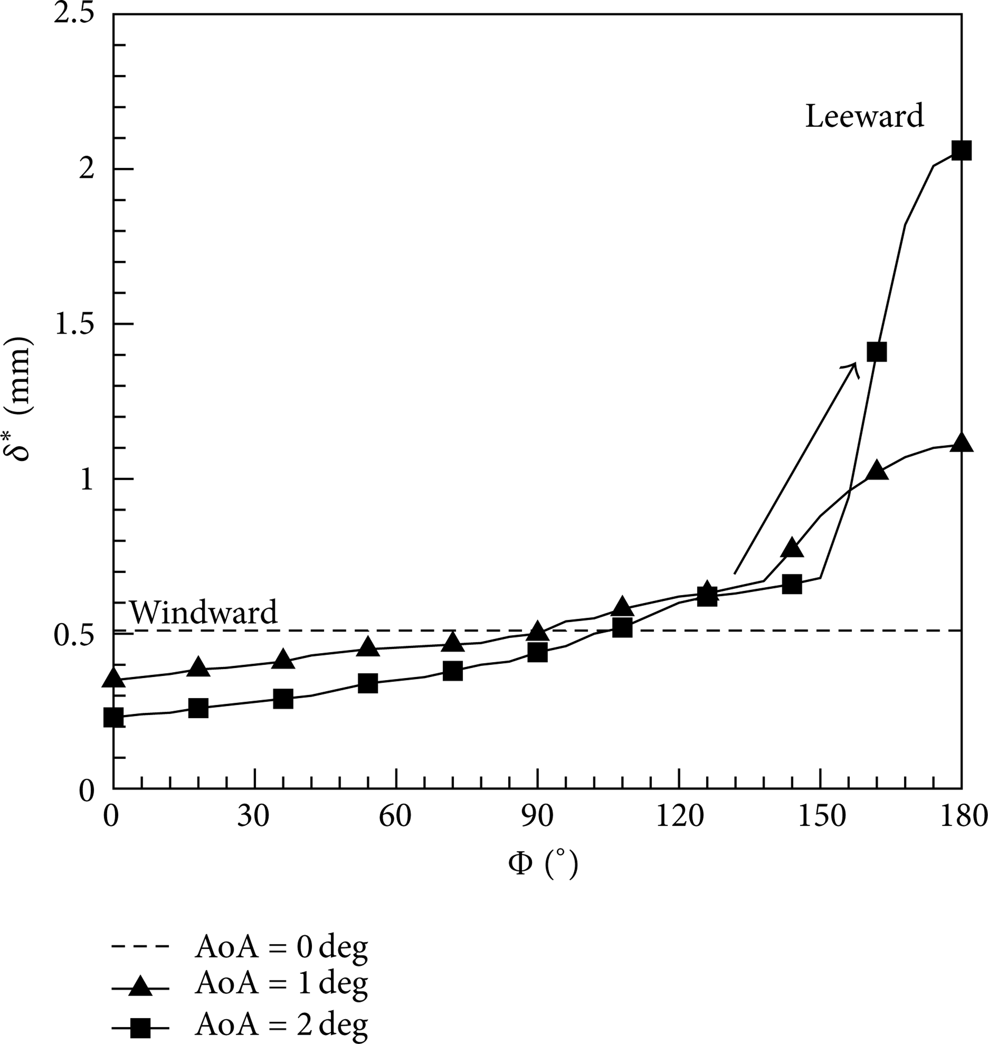
Comparison of displacement thicknesses.
3. Linear Stability Theory Analysis and Validation
Based on the local parallel assumption, the stability characteristics at different regions are calculated by LST method after obtaining the steady flow. The linear stability equations for the compressible flow were solved by symmetric compact difference schemes with 8th order [18]. Assuming the disturbances are traveling waves, which are defined as f′(x, y, z, t) = [u′, v′, w′, T′, p′] T , the form of disturbance waves is expressed as

where
In order to validate the LST method, stability of Stetson's blunt cone [20] with the 3.81 mm nose radius has been carried out. Stetson performed hot-wire measurements in the boundary layer of a blunt cone at 0° angle of attack and Mach number 8 in Tunnel B at the AEDC. The Stetson experiment has been analyzed by numerous other researchers using many different codes, which makes it an ideal benchmark for wind tunnel cases. Figure 4 gives the comparison of velocity profile at s/r n = 175 with Esfahanian [21]. Figure 5 shows the amplification rate at s/r n = 175 published by many other researchers and present calculation. The computations in Figure 5 agree much better with each other than they do with the experimental data. So this LST code used in this study can obtain accurate stability analysis results.
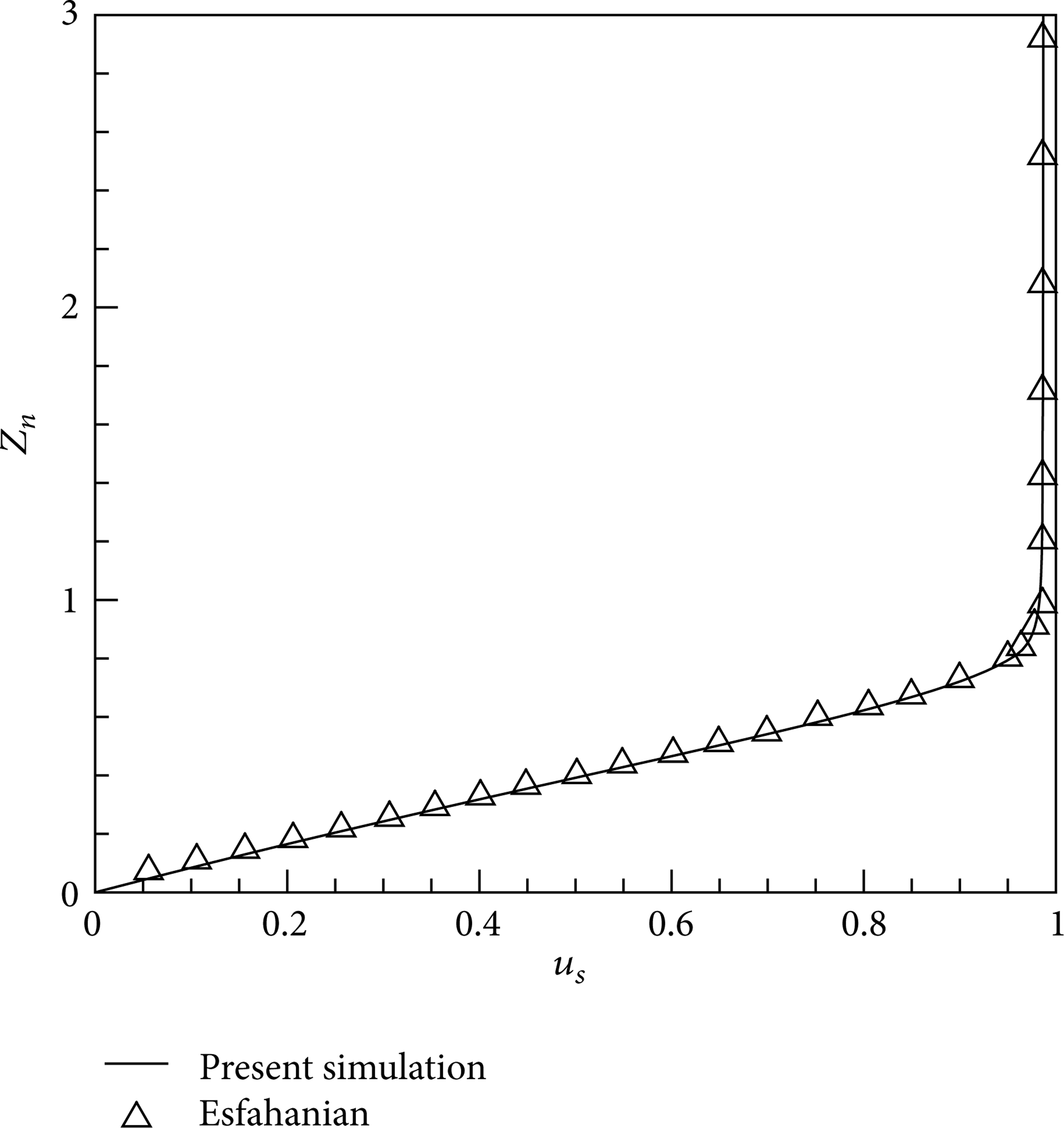
Streamwise velocity profile at s/r n = 175.
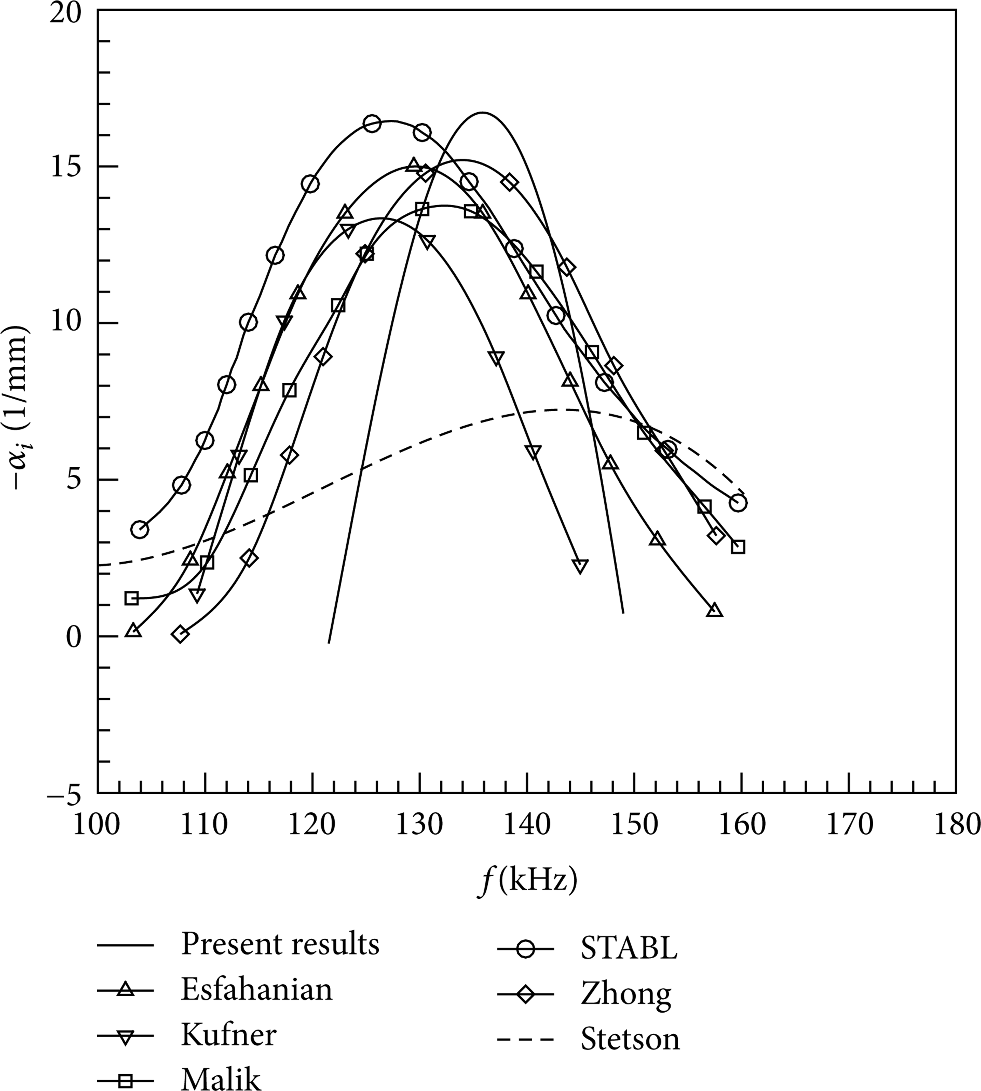
Growth rate at s/r n = 175.
4. Results and Analysis
4.1. First Mode and Second Mode Wave
First mode and second mode wave have been found at different rays. Figure 6 shows the first mode growth rates at different azimuthal angles at X/R n = 200.9 for α = 0°, 1°, and 2° case. It is found that the unstable wave only appears on the leeward ray for the first modes, and, on the other rays, the first modes are stable or nearly stable. The stability characteristic of first mode is actually complex; first mode contains multiple branches at a position. Figure 7 shows there are 5 branches which marked mod 1,…, mod 5 at X/R n = 200.9 at AoA of 2°. The curve of first mode in Figure 6 has the maximum growth rate in Figure 7. For instance, the curve of first mode Φ = 0° in Figure 6(b) is the curve of mod 2 in Figure 7(b). Moreover, different branch of first mode can transform at different position; for instance, mod 2, mod 4, and mod 5 transformed each other in Figure 7(a).

First mode growth rate at X/R n = 200.9.

Growth rates of first mode at X/R n = 200.9 at AoA = 2°.
Figure 8 shows the second mode growth rates at different azimuthal angles at X/R n = 200.9 for α = 0°, 1°, 2° case. For the second modes, the unstable wave exists on every ray, and the growth rate on the leeward meridian is larger than that on the windward meridian at the same streamwise location. The present results show that the boundary layer becomes more stable on the windward and less stable on the leeward meridian relative to zero-deg AoA case.

Second mode growth rate at X/R n = 200.9.
Figure 9 shows the comparing the maximum growth rate between first mode and second mode, it can be seen that the growth rates of the first modes are 1 to 2 orders of magnitude lower than those of the second modes. So the second mode waves are the dominated modes in hypersonic boundary layer as predicted by Mack's theory. Moreover, the circular frequency of the first mode wave is much smaller than that of the second mode wave. In the following analysis, second mode is considered primarily.

Maximum growth rate of first mode and second mode on the leeward.
4.2. Stability Characteristic along Streamwise Direction on Windward and Leeward Meridians
In order to obtain the stability characteristic along streamwise direction, LST analysis on different streamwise locations has been made on windward and leeward meridians. Figure 10 gives the growth rate of second mode at different streamwise locations. For α = 1° and 2° case. For α = 2°, unstable wave starts between X/R n = 124.5 and 143.6 on the windward meridian, while unstable wave starts less than 38.6 on the leeward meridian. So it clearly shows that unstable wave appears earlier on the leeward region than that on the windward. Figure 11 shows the maximum growth rate along the streamwise direction. It can be seen that the maximum growth rate on the leeward meridian is much larger than that on the windward meridian, which indicates that the velocity profile becomes unstable on the leeward meridian comparing to zero AoA. These results may give the reasonable explanation why boundary layer transition moves upstream on the leeward region and downstream on the windward region when a circular cone is mounted at small AoA.

Growth rate of second mode on the windward and leeward rays.

Maximum growth rate of second mode on the windward and leeward rays.
Moreover, there are some differences on unstable wave frequencies between windward and leeward. On the windward ray, high frequencies wave dominates the instability process, while low frequencies wave dominates the instability process on the leeward ray. That is related to the boundary layer thickness. For α = 2°, among the unstable frequency of second mode there seemingly exists an extreme value at low boundary; the extreme frequency value is 0.5, which means the frequency of unstable second mode wave on the leeward ray is larger than 0.5.
4.3. Stability Characteristic at Different Meridians
Figures 12 and 13 show the stability characteristics at different streamwise locations, X/R n = 100.7, X/R n = 200.9, and X/R n = 301.2. It can be seen that the growth rate does not vary monotonically from the windward ray to leeward ray. The stability characteristics at azimuthal angle around 150° are different; there is a “valley” region around 150° meridian. The corresponding relation between the maximum growth rate and azimuthal angle is given in Table 2 at different AoA. So details of the growth rate at the valley region are needed to be obtained and analyzed.
The corresponding relations between the maximum growth rates with azimuthal angle.


Growth rate of and second mode on the leeward at α = 1°.
Growth rate of second mode on the leeward at α = 2°.
The growth rate in the valley region is calculated in detail, which is shown in Figure 14. The maximum growth rate in the valley region changes with the AoA and azimuthal angle. At 2° AoA, the minimum value of the maximum growth rate in the valley region presents at 168° meridian. It illustrates that there is a minimum value of growth rate near the leeward ray; the growth rates in the valley region are much smaller than those of adjacent meridians. These results may give a reasonable explanation for the transition shape obtained by DiCristian's experiment [3]. Moreover, the valley region is an interface region, low frequency wave dominates near the leeward ray, and, on the other side, high frequency wave dominates.
Maximum growth rate of first mode and second mode on the leeward.
5. Conclusion
An investigation of AoA effects on the stability of hypersonic boundary layer over a circular cone has been carried out by LST method in this paper. First mode and second mode were both found; first mode contains multiple branches at a position, and the second mode is the dominated mode in hypersonic boundary layer over a cone. The growth rate of the most unstable wave on the leeward ray is much larger than that on the windward ray, and the unstable wave appears earlier on the leeward region than that on the windward. These results may give the reasonable explanation why boundary layer transition moves upstream on the leeward region and downstream on the windward region when a circular cone is mounted at small AoA. Moreover, it is found that the stability characteristic at azimuthal angle around 150° is different; there is a “valley” region around 150° meridian.
Conflict of Interests
The authors declare that there is no conflict of interests regarding the publication of the paper.
Footnotes
Acknowledgment
This work is supported by National Science Foundation of China under Grant 11102199.