
Abstract
There have been increasing demands for research into multi-channel-based wireless sensor network protocols and applications to support requirements such as increased throughput and real-time or reliable transmission. Researchers or developers of these protocols and applications have to simultaneously analyze the exchanged packets for correctness of both their contents and message exchange timelines. However, if developers were to use multiple conventional single-channel packet sniffers for this purpose, debugging during development and the verification process becomes extremely tedious and difficult because of the need to check the correctness of the protocols over multiple channels individually. Therefore, we present a multi-channel packet-analysis system (MPAS) that helps in debugging and verification for multi-channel protocols or applications. Wireless packets are detected and timestamped by each sniffer module in the MPAS for each channel, and packets are preprocessed and transmitted to a GUI-based analyzer, which then parses the received packets and shows them in order. We present the design and implementation results of the MPAS and evaluate its performance by comparing it against a widely used packet sniffer.
1. Introduction
Wireless sensor networks (WSNs) have become widespread in telematics and agricultural, military, industrial, and medical applications with the help of rapid advances in relevant technologies such as semiconductors, embedded software, and sensor technologies among many others. In accordance with the growth of the WSNs, the limited industrial, scientific, and medical (ISM) frequency band that is commonly used by WSNs has become so crowded that communications protocols based on a simple single-channel system have a difficult time in providing applications with sufficient throughput, reliability, and timeliness. In a single-channel system, reliability decreases due to interference from communications on common or adjacent channels and from noise level. Therefore, there are increasing research and standardization efforts, such as time-synchronized mesh protocol (TSMP) [1], IEEE 802.15.4e, ISA100.11a, WirelessHART, and other related protocols, into developing multi-channel communications protocols.
Research and development for multi-channel communications protocols or applications usually require convenient and accurate debugging facilities, such as a packet sniffer or analyzer, to verify performance. Although there have been studies and developments of single-channel packet analyzers, there is a distinct lack of work looking into multi-channel packet analyzers. One possible method to overcome the problems of analyzing multi-channel protocols is to use a set of single-channel packet analyzers. However, this is a rather naïve approach, and one of the severe problems with this approach is the lack of time synchronization between the single-channel packet sniffers. Therefore, we propose a multi-channel packet-analysis system (MPAS) that can monitor multiple channels at the same time and which is easily extensible and time-synchronized between sniffer modules. This system can be used to analyze any frame that follows the standard IEEE 802.15.4 MAC frame format and the IEEE802.15.4 2.4 GHz direct sequence spread spectrum (DSSS) physical layer (PHY) [2]. We evaluate the strengths of this system from the viewpoints of scalability, synchronization between sniffer modules, and frame analysis rate by comparing it against a well-known packet sniffer, SmartRF [3].
The rest of this paper is organized as follows. Section 2 presents related works, Section 3 describes the design and implementation of the proposed MPAS, and Section 4 evaluates its performance. The paper concludes with a summary of our work and a statement of future work in Section 5.
2. Related Works
There have been increasing efforts in research and development on IEEE 802.15.4 radio packet-analysis due to demands from diverse applications, including industrial process control and automation. Most IEEE 802.15.4-compatible transceiver vendors have led packet-analysis tool development for the last decade, based on their transceivers and development kits. This is because a packet-analysis tool usually consists of visualization software and a packet-capturing hardware module, the core of which is a radio transceiver. Texas Instruments, which merged with Chipcon Inc., the developer of the most widely used IEEE 802.15.4-compliant transceiver, the CC2420, has a single-channel packet sniffer [3] available in its development kits. Microchip released the ZENA wireless network analyzer [4], which uses an analyzer board based on its IEEE 802.15.4 transceiver. NXP Semiconductor, after its acquisition of Zennic, also provides a protocol analysis tool [5], with its sniffer node utilizing its own radio transceiver. Some vendors developed their own analysis software, while others are using the well-known network protocol analyzer Wireshark [6]. However, most of the packet-analysis tools basically target single-channel analysis.
There is also some research activity in Academia on packet-analysis tools. Ban et al. [7] presented an IEEE 802.15.4 packet analyzer that consists of a server process running on an Intel PXA 270 evaluation board with CC2420 and a client graphical user interface (GUI) application running on a PC. This client/server-based analysis system can capture and analyze only a single-channel. Choong [8] proposed a multi-channel packet-capturing system where the capturing device is based on Universal Software Radio Peripheral version 2 (USRP2), a simple and flexible platform for software radios, and GNU Radio, an open-source software development toolkit that provides signal processing blocks to implement software radios [9]. The system uses a Macbook with a 2.4 GHz Intel Core 2 Duo processor and 2 GB of RAM to run GNU Radio to capture five different channels at the same time. Wireshark is used as an analysis software for the captured packets. The main goal of this work seems to focus on demonstrating the possibility of software defined radio (SDR) rather than proposing an analysis or verification tool. Pöttner and Wolf [10] demonstrated a packet-analysis system with Wireshark and a standard off-the-shelf hardware platform, TELOSB/TMote Sky [11], running the Contiki operating system [12]. Ferrari et al. [13] proposed a WirelessHART distributed packet analyzer, which consists of a monitor station and distributed field-programmable gate array-based probes connected by an Ethernet measurement network. With help of digital detection hardware, they could achieve high accuracy of synchronization between distributed probes. Koubâa et al. [14] presented monitoring and analyzing software, Z-monitor, which uses a commercial off-the-shelf (COTS) sensor node, such as TelosB, to capture frames.
Existing packet-analysis tools cannot meet the requirements (multi-channel scalability, synchronization support, simultaneous monitoring of all channels with acceptable frame capturing rate, and cost) for developing and verifying multi-channel protocols or applications using such protocols, so this paper proposes MPAS to resolve these issues. Table 1 summarizes and compares the aforementioned works and MPAS.
Comparison between different packet-analysis tools.

Number of channels evaluated (maximum channels supported). IEEE 802.15.4 2.4 GHz PHY defines 16 channels.
Monitoring for multiple channels at the same time with acceptable frame capturing rate (FAR).
Time synchronization between different sniffing modules.
3. Multi-Channel Packet-Analysis System
MPAS consists of multi-channel packet sniffer (MPS) hardware and GUI-based multi-channel packet analyzer (MPA) software, as seen in Figure 1. The MPS is based on multiple scalable sniffer modules and a time synchronizer module. Each sniffer module monitors one of the 16 channels for IEEE 802.15.4 at 2.4 GHz, and the MPS can be easily scaled up to sniff another channel by adding a new sniffer module. The time synchronizer module synchronizes all the sniffer modules in the MPS through the use of a synchronization button that stimulates the start of a time synchronization protocol concurrently on all the sniffer modules. The hardware button is used to reduce the uncertainty of a software based approach. As long as each sniffer module is synchronized, it captures every packet in its channel, wraps the packet in the universal asynchronous receiver/transmitter (UART) message format, which is explained in Section 3.2, and then sends it to the MPA. Finally, the MPA receives the message from the MPS, analyzes it, and displays the packets in the analysis output window.

Multi-channel packet-analysis system (MPAS) overview.
3.1. Multi-Channel Packet Sniffer
The MPS is a scalable and easily extendable sniffer that consists of multiple sniffer modules and a time synchronizer module. Rather than designing a new hardware platform for the sniffer module, we adopt a COTS platform, the MSP-EXP430F5438 [15], from Texas Instruments Inc., based on an MSP430F5438 microcontroller unit and a CC2520EM IEEE 802.15.4 transceiver module [16], as seen in Figure 2. To monitor multiple channels simultaneously, each sniffer module fixes its channel without switching the monitoring channel dynamically while sniffing. We build another component of the MPS, a time synchronizer module with a low-pass filter hardware reset switch. To start packet sniffing, we initiate time synchronization between sniffer modules by pressing the reset switch, and the time synchronizer generates a hardware signal to all the attached sniffer modules. A general purpose input/output (GPIO) pin in each sniffer module is used to capture the hardware signal from the time synchronizer to synchronize the sniffer modules with each other. The hardware signal triggers an interrupt on each sniffer module, and the sniffer module initializes its time reference. The software platform of each sniffer module is based on TIMAC 1.4.0 [17], and we modified TIMAC to promiscuously capture every frame in the radio communication range. To receive the packet regardless of the destination address, the MAC radio RX frame filtering function needs to be turned off.

Packet sniffer module.
Whenever a sniffer module captures a frame, it also timestamps the frame. The captured frame with the timestamp and the channel number is passed to the application layer with the help of the OS abstract layer (OSAL) message-passing application programming interface (API), and the MPS application encapsulates it using the UART message protocol specified in Section 3.2. Finally, the sniffer module sends the UART message to the MPA via the USB2UART bridge chip. Since each sniffer module has a USB interface, the MPS is easily extended and scaled up using a USB hub, as seen in Figure 2(a), which shows three sniffer modules and a synchronizer.
3.2. UART Message Protocol
When the captured MAC layer frame is to be sent to the MPA, the MPS application adds the channel information and the time information, which is the synchronized frame reception time seen in Table 2. When the MPS application sends the UART message, it needs to manage the start and the end of the message with special control bytes. 0xAA and 0x7E are used for the start of text (STX) and the end of text (ETX), respectively. In addition, the control escape (ESC) 0x7D is required to discriminate STX, ESC, and ETX in the body of a message. If one of these special characters is included in the body of a UART message, ESC is transmitted first, followed by the original octet exclusive-or'd with 0x20. We adopt this framing protocol from RFC1662 [18].
UART message frame format excluding STX/ETX.

3.3. GUI-Based Multi-Channel Packet Analyzer
The MPA is designed to receive UART messages from each sniffer module in the MPS to analyze the wrapped MAC frames and display them. The MPA consists of a port control block, an analysis block, and a display block, as seen in Figure 1.
To support the multiple sniffer modules in the MPS, the MPA is implemented in a multithreaded model. The MPA performs (in sequence) port scan, port open, thread run, and the thread repeats to read its own port, analyzes the read message, and displays it in a list control. First, the port control block searches and reads the available serial port lists in the Windows system registry. Second, the user selects and opens some of the available ports. When the selected ports open, a thread for each port is created and starts at the same time. If data is ready in an open port, the thread for the port reads the data. When the thread receives the entire UART message, it starts to parse it based on the message protocol specified in Section 3.2. The analysis result is shown in the packet list in Figure 3. The MPA window is divided into packet list and detail view. The packet list is a list control instance, and the user can identify each packet type (beacon, data, ACK, and command) with a unique color for each frame type. It displays the subfields of the message, such as channel number, timestamp, MAC header (MHR), MAC payload, correlation, link quality indication (LQI), received signal strength indication (RSSI), and MAC footer (MFR). Also, the packet list supports different colors according to each frame type.

Packet list screen on the multi-channel packet analyzer.
Detail view shows the details of a selected packet (fourth packet in Figure 3, line highlighted in light blue) from the packet list view, and each field of the frame and packet is parsed and appended with more details to assist the user in analyzing the packet, as seen in Figure 4. Another feature of the MPA is the Save function, which allows the user to save the analyzed frames for export to other software or for offline use.
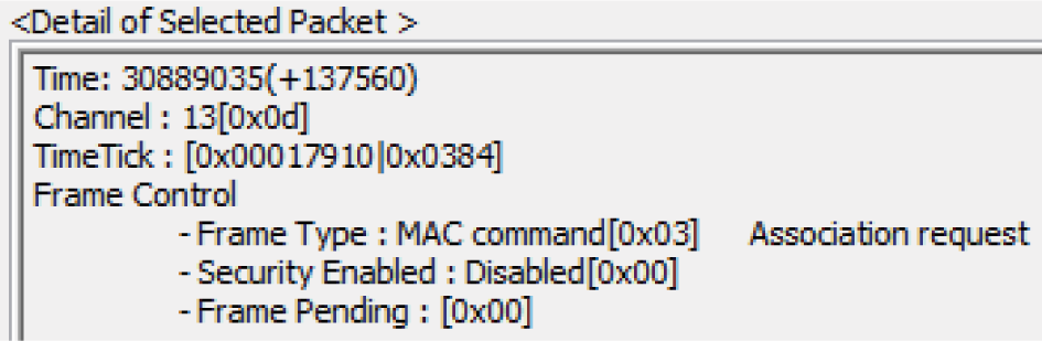
Packet list screen on the multi-channel packet analyzer.
4. Evaluation
We evaluated the performance of the MPAS by comparing it to a widely used packet sniffer [3], as set up in Figure 5. The basic metrics for this evaluation are frame analysis rate (FAR) and timing accuracy. FAR indicates how many frames are captured by the MPS and how many captured frames are shown and finally analyzed in the MPA. We use a sender/receiver pair to evaluate each channel. A sender transmits a 20B MAC service data unit (MSDU) to a receiver, to which the receiver then responds with a 10B MSDU. Meanwhile, every data frame requests an acknowledgment frame, so a transaction started by the data frame (request message) from the sender consists of 4 MAC frames (data/acknowledgment and data/acknowledgment) exchanges between the sender and the receiver.

Experimental setup with three sniffer modules, time synchronizer, and sensor nodes for three-channel test.
The sender is configured to send a request message (data frame) to the receiver every 100 ms. The frame analysis rate is presented in Table 3, and a total of 1000 data and acknowledgment frames for each test are used to measure FAR. The minimal interval for any successive frame has been measured to be 991 μ sec for a data frame and the corresponding acknowledgment frame.
Frame analysis rate.

A SmartRF packet sniffer captures every data frame and the corresponding acknowledgment frame. The MPAS analyzes 100% of the frames for a single-channel measurement, which means that the MPS can capture 100% of the frames. Since each sniffer module in the MPS runs independently, the MPS is inherently scalable, and we can expect all the individual sniffer modules of the MPS to capture every frame. Actually, even for three channels, as seen in Figure 3, the MPAS could analyze every frame over the channels. However, with four and five channels, the MPAS shows unexpected FARs of 98.3% and 95.7%, respectively. It does not mean that MPS misses some frames. As mentioned, each sniffer module of the MPS can capture every frame in its configured channel. Although the MPS captures all the frames over multiple channels and reports them to the MPA, the monitoring software running on a PC may not completely process every serial port in time, depending on the number of sniffer modules in the MPS. Since each sniffer module in the MPS runs independently, it can capture every frame for the specified channel. In other words, the bottleneck is the MPA, and we intend to upgrade the current implementation to cope with the load.
In addition, we also evaluated the common time base operation over multiple sniffer modules in the MPS. When we start the measurement, a time synchronizer triggers each sniffer module to align its time base for timestamping any captured frame. During the operation phase, each sniffer module reports the captured packets to the MPA, and the MPA needs to be able to align all of the frames analyzed in multiple channels with a single time base. Figure 6 shows the data and the corresponding acknowledgement frames exchanged in two channels (0x0b and 0x0c). The dotted red rectangle indicates out-of-order frames, and the solid light blue rectangle shows the ordered frames according to a single time base.

Time base alignment over two channels.
We evaluate the timing accuracy more in detail, in a single-channel and over multiple channels. To measure the timing accuracy, we use the same applications as described in FAR measurements. For a single-channel analysis, the timing accuracy of MPAS compared to that of SmartRF packet sniffer is summarized in Table 4, and it shows the statistical results of the cumulative time deviation due to the clock deviation between both devices. In addition, the MPAS has been analyzed in detail, and we found that it has potential problems due to the inaccurate crystal and round-up error to make internal integer valued clock divider. Actually, we designed MPS to run at 12 MHz, but the actual measured frequency was 11.999 MHz and 12.032 MHz, depending on the selected divider value. The right most column was measured for 12.032 MHz, which is faster than the target speed, 12 MHz. Thus it generates more ticks for the specified period and biases the estimated time by the MPS to a positive value. Conversely, the slower clock, 11.999 MHz, generates less time-ticks for the same time period, and the estimated time is less than the actual time. After analyzing the time deviation, we applied a simple linear transformation based on the nominal clock speed and the actual clock speed to the original dataset after considering the actual clock speeds to compensate for the deviation. As a result, the time deviation was reduced drastically as shown in the compensated section of Table 4. Detailed deviation is summarized in Figure 7.
Time accuracy in a single-channel.


Original cumulative time deviation (a) versus compensated one (b).
We also evaluate the synchronization accuracy among sniffer modules in MPS, which is one of the most important requirements for a multi-channel packet-analysis tool. Instead of using multiple channels, a common channel is used to measure the time deviation between the different sniffer modules. Note that all of the sniffer modules in MPS can capture any frames as well as a broadcast frame and they can capture all of frames transmitted in the common channel. When a frame in the common channel is transmitted to the different sniffers, there are different interrupt fetch latencies under 1 us depending on the internal state of each MCU and the distance from the broadcasting node. The accuracy of the initial offset adjustment is less than 1 us, but the ongoing time deviation is accumulated as in the previous experiment. Figure 8 shows the measurement results from irregular sampling periods. Two nodes, 0x0C and 0x1C, show quite similar characteristics in the clock drift while 0x2C displays a large deviation in its drift from them. The large clock drift motivated us to do the last evaluation.

Time deviation (us) between 3 sniffer modules for 417 seconds.
As long as each sniffer uses a different clock source, we cannot avoid clock deviations that increase as a function of time. However, if we use the same reference clock, the deviation between all sniffer modules is bounded to a certain interval that is a function of the interrupt subroutine and instruction cycle. To implement the common clock source, we set one of the sniffer modules to be the master source. The master routes its timer clock source, SMCLK (subsystem master clock with a nominal speed of 12 MHz), to the other sniffer modules as their timer clock sources. The other sniffer modules will then use the same clock source for their timer modules to perform timestamps. Now, when the MPS turns on, the master sniffer module starts its SMCLK. When a user presses the hardware synchronization button, all the sniffer modules in the MPS start their timers using the common reference clock given by the master sniffer, and the timer count values are aligned. Figure 9 shows the result from the common clock reference usage. Unlike the result in Figure 8, Figure 9 shows that the time deviations between sniffer modules only have small-scale fluctuations around a larger constant deviation even as the measurement time elapses, compared to the previously increasing deviation as a function of time. Table 5 describes the detailed statistics, which shows that the deviations are between −1.33 us and 1.08 us. Our new design obviates the need for constant over the air synchronization.
Time deviation (us) with a common clock reference.


Time deviation (us) between 3 sniffer modules with a common reference clock for 434 seconds.
5. Conclusion
This paper presents an MPAS architecture and implementation designed to make research and development into multi-channel communications protocols easier. The hardware capturing system, MPS, consists of multiple COTS packet-sniffing modules that run independently and that are inherently scalable. The MPS also contains a time synchronizer for the attached packet-sniffing modules. The MPA is the monitoring and analyzing software for the MPS. To see the feasibility of MPAS, we implemented it and evaluated the implementation. According to our evaluation, the MPAS outperforms a widely used packet sniffer in FAR and can be scaled up to monitor multiple channels. With the evaluation of the implementation, we raised some issues such as clock drifts, delays in serial communications between the MPS and the PC, and varying interrupt handling delays that need to be taken into account to improve the performance. Future work will include research into easier and periodic time synchronization in the MPS, performance improvement under MPA overload, and minimization of the size and the cost of the MPAS.
Footnotes
Conflict of Interests
The authors declare no conflict of interests regarding the publication of this paper.
Acknowledgments
This research was supported by the Basic Science Research Program through the National Research Foundation of Korea (NRF) funded by the Ministry of Science, ICT and Future Planning (no. 2011-0014204). Jeonghwan Bae, Tae-Soo Kim, Hiecheol Kim, and Seong-eun Yoo presented a preliminary result of this work at EWSN 2014 demo session [![]() ].
].