
Abstract
Because bolt usages always have the requirement of tensile strength, with a view to reach the requirement of tensile strength, the material property or forming method and dies design can be used to obtain it. The study aims at the forming method and dies design to perform the multistage analysis of bolt to realize the effect of forging stream line continuity on tensile strength. The study uses Simufact-FEM software to do the multistage forming simulation to modify the dies design and forming method. The amount of broken forging stream line can be used to identify whether the bolt is good or not. From the comparison of realistic forging product, the results can verify the acceptance of FEM simulation.
1. Introduction
Kim and Im [1] think that different multistage forming methods have been proposed by focusing on different product requirements; thus different multistage forming methods will have different mechanical conditions for end products. In addition, during forging it will also affect the lifespan of molds and the quality of products and further affect the production progress. The forging processes are nothing more than the following methods, including upsetting, forward extrusion, backward extrusion, combined extrusion, and punching or trimming. Different multistage forming methods indicate those forming ideas and concepts for making products and arrange them in different orders; thus different forming methods will decide the sizes and dimensions of materials, the selection of machines, and the design methods of dies. Generally speaking, when selecting appropriate forming methods, one needs to consider whether these methods conform to the production conditions, such as the number of stages, the forging force for the individual stage and whole forging process, the diameter of wires, the dies, and the length of front/rear punch. Additionally, the simulation of forming method needs to understand the distribution of effective strain and stress for final products, and the forging force for each stage also needs to be controlled within a proper range. Li et al. [2, 3] think that the design direction of multistage forming method generally depended on subjective working experience and technologies of designers, but there still are insufficient experiences or undistributed considerations. For the manufacturing of product, the most important issue is that how to use the lowest costs, including money and time, to produce better products. Therefore, in order to shorten the lead time of designing the forming methods, reduce the cost of dies and use proper forming methods for machines; thus it is necessary to look for effective methods. In recent years, due to the accelerating computation and lowering cost of computers, it makes a significant advancement of design and development for metal forming by using Finite Element Method (FEM), especially it produces a more precise, rapid, and stable simulation tool.
When carrying out the software simulation analysis, Nagaile et al. [4–7] conduct actual cylinder compression test and ring compression test in order to obtain actual forming flow stress formula and frictional factor; among which, use billet to conduct the cylinder compression test, and lower frictional factor as possible to be zero (m = 0), so as to obtain the relation equation between actual strain and stress for materials; in addition, it can be used as the relation basis that yielded from materials’ strain and stress when they are receiving forces during the software simulation. Moreover, the ring compression test needs to use the specimens with certain size and select the lubricating conditions as close as actual forging process to carry out the compression test then the measurement and the simulation of estimation, in order to obtain the m value of constant shear frictional factor as the parameter basis for the software simulation analysis. Canta et al. [8] carry out the finite element simulation and analysis on the spark plug and use Superform software to conduct the simulation for the process of plastic deformation, and the results are consistent with the actual products. Buijk et al. [9, 10] use Simufact-forming software simulation to adjust the 6-stage cold forging forming method. First they explore the forming force for each stage to select the beneficial preforming shape in order to make the force be an equalized status in each stage. It mainly intends to increase the force within the range of bearing capacity for dies in the stage with lower force to share the partial forming force for the next stage and reduce and lower the force for the stage with higher load originally. Therefore, die's lifespan can then be extended since the force of each stage become more balanced and reached the proper forming method of production.
As a result, Crowgey [11] uses the simulation analysis software, except for greatly increasing the efficiency of making dies, shortening the production cycle of new products, and increasing the lifespan of dies; it also can provide new-coming designers with the prompt understanding of forming method, the analysis of defect, and the improvement of simulation. Therefore, it can save great time of preprocess planning to further upgrade the design level of dies.
2. Finite Element Simulation
2.1. Research Purpose
In addition to the size of bolt that needs to conform to certain specifications, the tensile strength in mechanical conditions also has to conform to the level standards. In the forming process, it not only requires the dimensions of dies but also needs the level of integrity for the forging stream line which is the joint between bolt head and grip, and it can be considered as another key indicator for reacting tensile action. And the level of integrity for forging stream line will be significantly varied due to different forming methods. Therefore, we use the Simufact simulation software to conduct the simulation for the forming method and the modification of dies dimensions and set the forging stream line on materials, in order to attach it to the node of grids. Along with the material deformation occurred by load and the node move, the final number of breakage for the forging stream line caused by the plastic deformation in the joint between the head and grip can be used as the basis of determining whether the tensile strength capability of finished bolt product reaches the requirement or not.
2.2. Bolt Specification and Testing Result
The specification of bolt is BSW1/2-12p-L160, which stands for that BSW1/2-12p is for its thread, and the length is 160 mm. The diameter of grip should be 11.22 mm, and head diameter should be 24 mm. The total length should be 168 mm including the head, and the tolerant R-angle for the joint between head and grip can be 0.4 mm to 0.8 mm; the details are shown in Figure 1. Its material is AISI1010 carbon steel and requires 4T strength for bolt; that is, the tensile strength of finished products should be more than 40 kgf/mm2 (392 MPa).
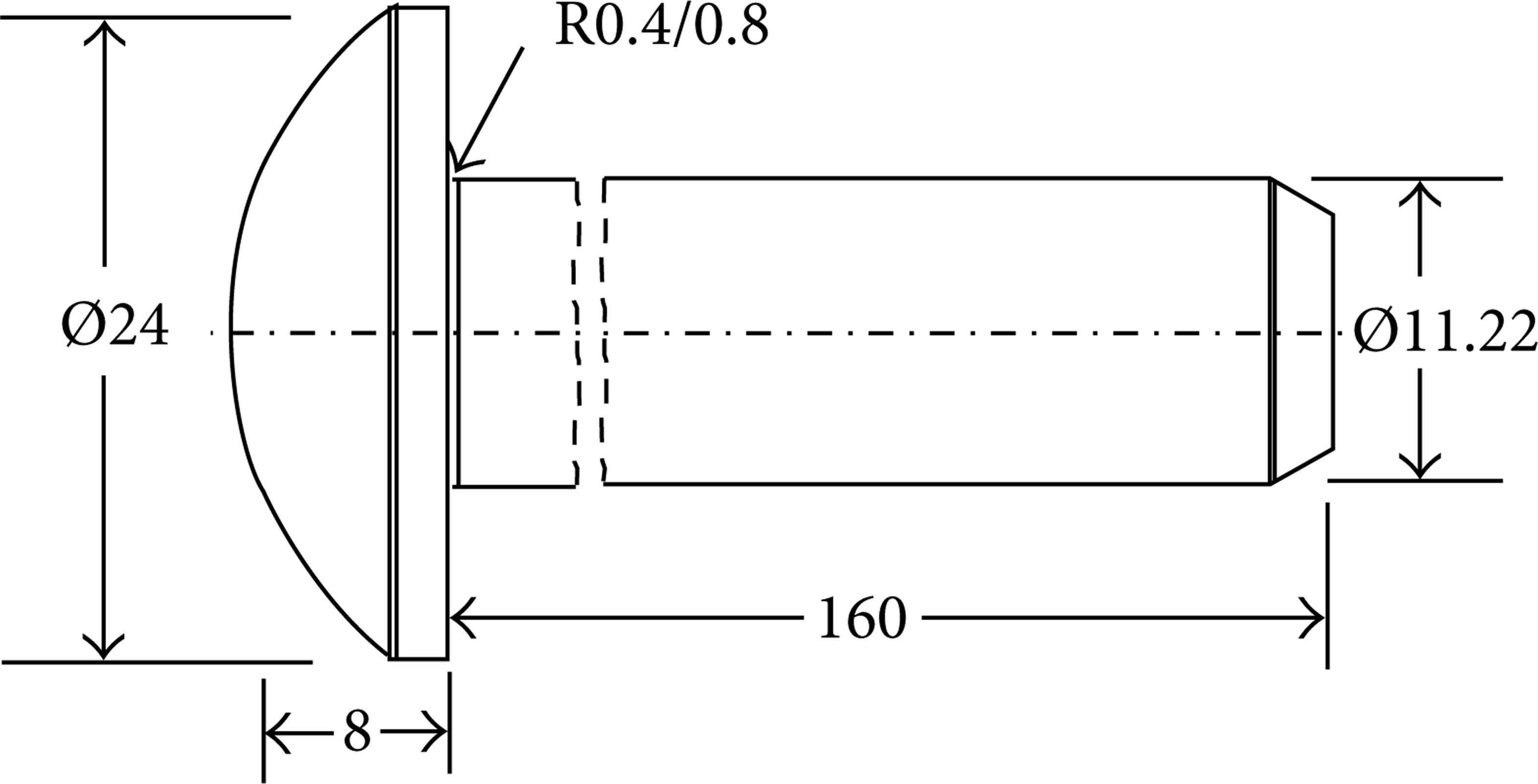
Dimensions of bolt.
Design of the original forming method is shown in Figure 2, which uses a 3-stage horizontal screw forging machine to produce the bolt product. It selects feeding materials with the diameter of 11.04 mm, the length of 189.5 mm, and the volume of 18140.00 mm3, and the cavity diameters of dies are 11.07 mm, 11.14 mm, and 11.22 mm, respectively, for the 1st, 2nd, and 3rd stages. All 3 stages are carried out by using the open die upsetting method; it is a preformation at the 1st stage, the preformation is carried out to roughly distribute the volume of the head and grip. At the 2nd stage, the shape of the head is almost preformed. The 3rd stage is the procedure of upsetting forming for the head, and the R-angle is 0.4 mm for the joint between the head and grip.

Original forming method of bolt.
Figure 3 shows a forming finished product manufactured by the original forming method, which carries out the tensile strength test by using the universal testing machine till the product breakage, and its tensile strength is only 29.7 kgf/mm2 (291.36 MPa), which is lower than the required strength, 40 kgf/mm2 (392.4 MPa); thus it is apparently not conformed to the required specification.

Tensile test result of finished product by using universal testing machine.
Generally speaking, manufacturers will think that the insufficient tensile strength is caused by the decarburization of wires or the improper selection of materials; however, this is not really the fact. Thus, with the view to explore the causes of insufficient strength, the researcher corrodes the cross-section of finished product and uses the optical microscope to observe the distribution of its forging stream line, as shown in Figure 4, where the diameter with continuous stream is around 2.7 mm with R = 0.4 mm. In general, the most optimal distribution of forging stream line shall be a complete connection from the head to grip without any breakage; even if there is a 90-degree bend between the head and grip of finished products, the forging stream line must be successive to be able to take the maximum required tensile strength. However, Figure 4 shows that there are certain breakages of forging stream line under the head; the integral successive forging stream line from the grip to the head is only 1/2 of the grip diameter. The rest has no successive breakage; that is, when conducting the tensile test, almost all the loads bore by the 1/2 of the grip diameter, which is only accounted for 25% in cross-section area, and this is possibly one of the key causes of insufficient tensile strength for bolt. As a result, it uses the finite element simulation software (Simufact-forming) to conduct the forging stream line simulation.

Defect of bolt forming (R = 0.4 mm).
2.3. FEM Forging Stream Line Analysis
It uses the Simufact simulation software to simulate the forming method shown in Figure 2, and the joint between the head and grip in the 3rd stage is the same as the original forming method with setting R-angle as 0.4 mm. In addition, set the vertical stream line on the initial materials (cut-off) to make such stream line change along with the material flow during the plastic deformation. The stream lines of original forming method for each stage are shown in Figure 5. At the 3rd stage, it is noted that some stream lines in the joint are broken.
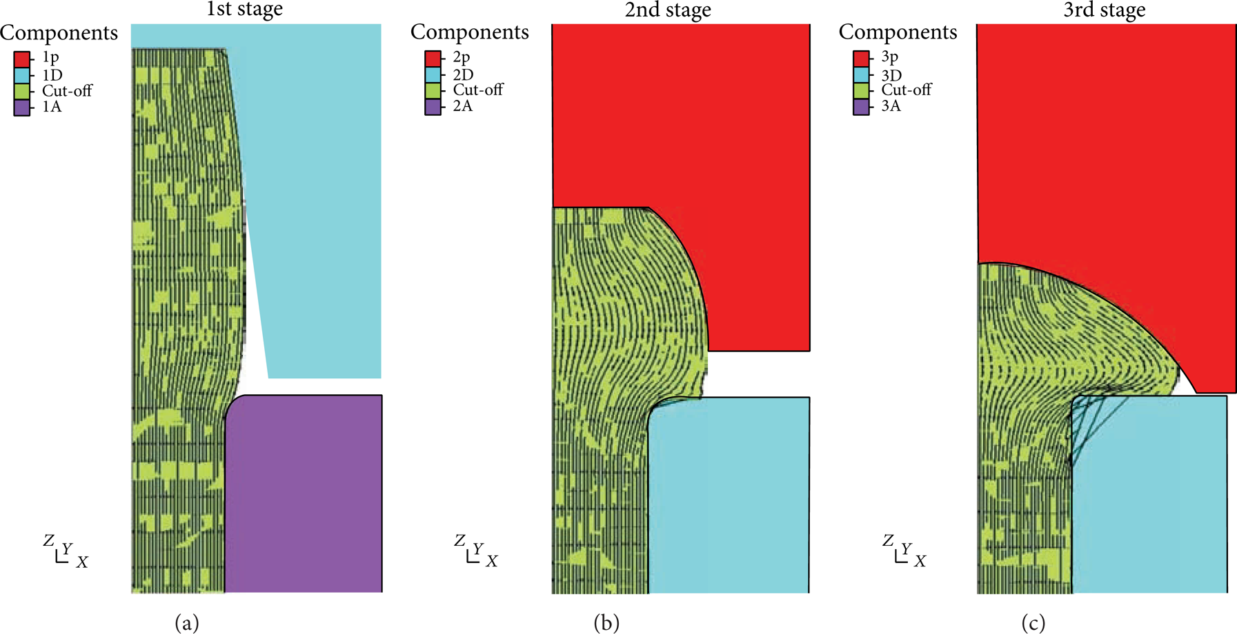
Forming simulation result of original forming method for each stage.
Figure 5 shows that this forming method resulted in breakage on partial forging stream line at the 2nd stage and yielded even more breaking forging stream lines at the 3rd stage. The magnified simulation result at the 3rd stage is shown in Figure 6.

Forging stream line simulation status of different R-angles.
Simulation 2 (Figure 6(b)) is the simulation setting the R-angle of die as 0.8 mm, and Simulation 1 (Figure 6(a)) is the simulation result using the original forming method with setting the R-angle of die as 0.4 mm, and this condition is identical to the actual forging die. The range is from the center to 2.79 mm for measuring intact forging stream line in this figure, and the radius of grip is 5.61 mm. Therefore, the ratio of intact forging stream line is only accounted for 24.7% of the cross-section area for the grip, which is very similar to the result of actual forging finished product.
The result obtained in “Simulation 2” is the range of intact forging stream line, from the center to 3.44 mm. The ratio of intact forging stream line is accounted for 37.6% of the cross-section area for the grip. Obviously, it is able to reduce the number of breakage for the forging stream line and increase the area of bearing the tensile when increasing the R-angle of die from 0.4 mm to 0.8 mm.
Comparing Figure 6 with Figure 4, the error between simulation (2.79 mm in Figure 6) and experiment (2.7 mm in Figure 4) is 3.33%. It is noted that the simulation result is in good agreement with the experiment. Its tensile strength with R = 0.4 mm is only 29.7 kgf/mm2 (291.36 MPa), which is lower than the required strength, 40 kgf/mm2 (392.4 MPa); thus it is apparently not conformed to the required specification.
Figure 7 is realistic bolt forming with R = 0.8 mm; from this figure the diameter with continuous stream is around 3.4 mm with R = 0.8 mm, and the error between simulation (3.44 mm in Figure 6) and experiment (3.4 mm in Figure 7) is 1.18%. The tensile strength with R = 0.8 mm is measured as 54 kgf/mm2 (529.74 MPa); it is quite satisfactory for the required strength, 392.4 MPa. It indicates that increasing the filet can increase the amount of stream lines to increase the tensile strength.
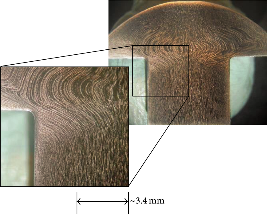
Realistic bolt forming for simulation 2 (R = 0.8 mm).
3. Analysis of Defect Causes and Improvement in Forming Method
The results mentioned above of forming simulation show that the insufficient tensile strength is caused by too many breakages of forging stream line. Thus, the exploration of the causes of breaking the forging stream line becomes a key direction for improving the defect. In the multistage forming process, in order to move billet to enter the dies cavity smoothly at the next stage, the internal diameter of dies cavity at the next stage will be generally bigger than the one at the previous stage, and it will cause a problem then.
For the original forming method shown in Figure 2, at the 3rd stage it conducts the head from the open die upsetting for the outer dies; at the beginning, the internal diameter of dies cavity for billet is the dimension at the 2nd stage, which must be smaller than the one at the 3rd stage; in addition, even considering the springback of material after billet departing from the dies cavity, the diameter of its grip is still smaller than the internal diameter of dies cavity at the next stage; otherwise it cannot enter the dies cavity at the next stage. When the head upsetting is slowly formed, the grip diameter has still not yet completely filled the gap between billet and dies cavity, and the punch continuously moves forward, the height of head decreases, the diameter increases, and the force increases; then the required volume for each of the head and grip is distributed. To reach the requirement for head dimension, the punch needs to move forward continuously; thus its force also increases continuously. At this time, the part material of the head enters the gap between the billet and dies cavity which causes the breakage of forging stream line for billet; the details are shown in Figure 8. The simulation order is from 1 to 4 in the 3rd stage; when the punch is continuously moving forward, the height of billet head will be smaller and smaller, but billet diameter will be bigger and bigger; thus the number of breaking forging stream lines will be more and more.
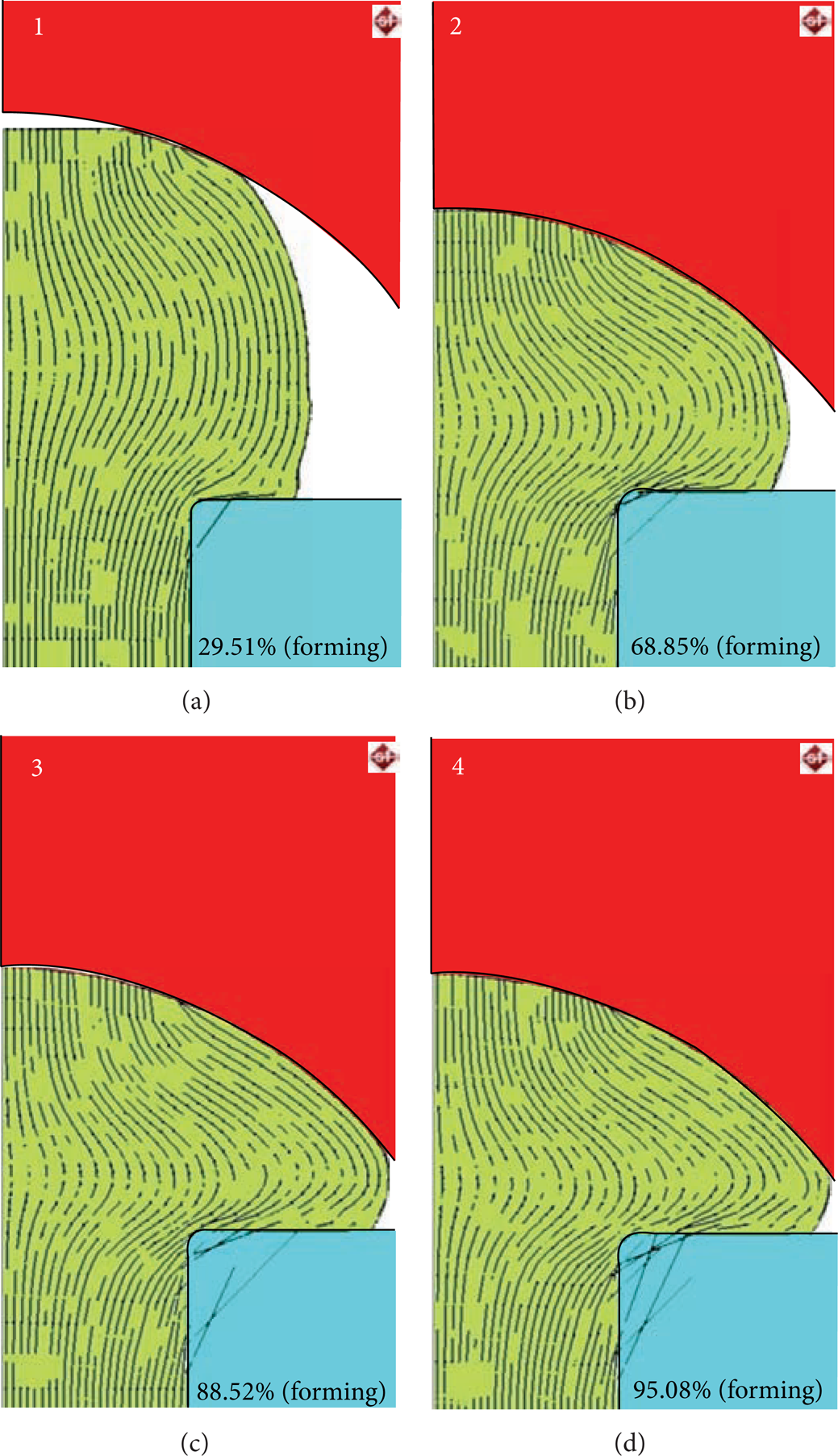
Simulation 1 changes in forging stream line at the 3rd stage simulation process (R = 0.4 mm).
Therefore, there is a significant correlation between the improvement in this problem and the dimension difference in the internal diameter of dies cavity. However, such a problem is that if there is a smaller dimension difference in the internal diameter of dies cavity at each stage, then it will be difficult to move billet to enter the dies cavity at the next stage. Additionally, as described in aforesaid section, change the R-angle of dies from 0.4 mm to 0.8 mm, and then it will have a little improvement in the breakage of forging stream line. This is because bigger R-angles can make material of head to smoothly squeeze into the gap in the grip.
3.1. Modified Forming Method
The original forming method (Figure 2) can be used to understand the preformation change at the 1st stage. Figure 9(a) shows the dimension of material extruding from the dies cavity when filling billet into dies cavity in the initial forging process; its height is 29 mm and diameter is 11.04 mm with a height-diameter ratio 29/11.04 = 2.62, and this ratio has already exceeded the upper limit of possible buckling phenomenon. In general, when conducting the upsetting process, it usually hopes to control the initial height-diameter ratio to be under 2 for materials; otherwise it may easily produce the buckling effect while upsetting. Now, such ratio is 2.62, and one must carry out the procedure of preformation in advance and then do the upsetting procedure in order to prevent from producing the buckling phenomenon.

Changes in dimensions before and after the 1st stage simulation forming of original forming method.
Figure 9(b) shows the dimension of the extruding part of billet from the mold at the end of forging process; its formed height is 21 mm and the maximum diameter of material is 13.2 mm; thus its height-diameter ratio is 21/13.2 = 1.59. This ratio is under 2 and indicates that, after conducting the preformation at this stage, it can conduct the next upsetting procedure. Therefore, it can determine that the 2nd stage and the 3rd stage of the original forming method as shown in Figure 2 are actually the same procedure and unnecessarily divided into 2 procedures; that is, the forming method for such bolt only needs the 1st stage and the 3rd stage to be completed; however, it will also yield the same result as aforesaid; thus the breaking problem of forging stream line still did not yet get a further improvement.
This is a 3-stage machine; thus it only uses 2 stages, and what is the function of the idle stage? As mentioned in aforesaid section, the breakage of forging stream line is caused by the gap between the dies cavity and billet. Therefore, the bigger gap will produce more breakage of forging stream line. In the original forming methods in Figure 2, all three stages are used as the procedure of conducting the head upsetting, but with specialized countermeasures for the grip diameter; thus the change in grip diameter is subject to the head upsetting, especially at the 1st stage and 2nd stage. The grip can hardly reach the dimension of internal diameter for the dies cavity of the grip; for example, after completing the formation at the 2nd stage, the grip diameter will be smaller than the internal diameter of dies cavity at the 2nd stage; as a result, when moving to the 3rd stage, the gap between the grip diameter and the internal diameter of dies cavity at the 3rd stage will be even bigger. Empirically speaking, when wires reach a certain level of roundness after drawing process, they will be, however, coiled up to form wire rod for the transportation convenience. When using the wire rod, it needs to be stretched by using the stretching table and held up by the material feeding table to conduct the forging process. After conducting a series of processes, the original roundness of wires no longer exists. Thus, the extra stage can be used to modify the roundness of material inside the die after cutting off the material.
After carrying out the analysis for these aforesaid questions, the researchers propose a modified forming method shown in Figure 9. New forming methods are the modified upsetting of closed dies at the 1st stage, the head preformation at the 2nd stage, and the completion of forging at the 3rd stage.
3.2. Modified FEM Forming Simulation
The Simufact simulation software is used to simulate the modified forming method as shown in Figure 10, and its result is shown in Figure 11. In addition, set the vertical stream line on the initial materials to make such stream line change along with the material flow during the plastic deformation and track material from the 1st stage and the 2nd stage to the 3rd stage for the changing status of stream line

Modified forming method.

Simulation result of modified forming method.
Figure 11 shows that this forming method is only a preformation at the 2nd stage, as the original forming method at the 1st stage, and the result does not have any breaking forging stream line, until the 3rd stage when it starts to make the breaking forging stream line. The magnified simulation result at the 3rd stage is shown in Figure 11.
Simulation 3 (Figure 12(a)) is the simulation result using the original forming method with setting the R-angle of dies as 0.4 mm. The range is from the center to 3.44 mm for measuring intact forging stream line in this figure, and the radius of grip is 5.61 mm. Therefore, the ratio of intact forging stream line is accounted for 37.6% of the cross-section area for the grip, which is the same as the result in Simulation 2, and it also shows that, even if the forming method changed and the R-angle of mold was set as 0.4 mm, the result is still identical to the one of the original forming method with setting its R-angle as 0.8 mm; thus it indicates a great improvement in the forging stream line after modifying the forming method.
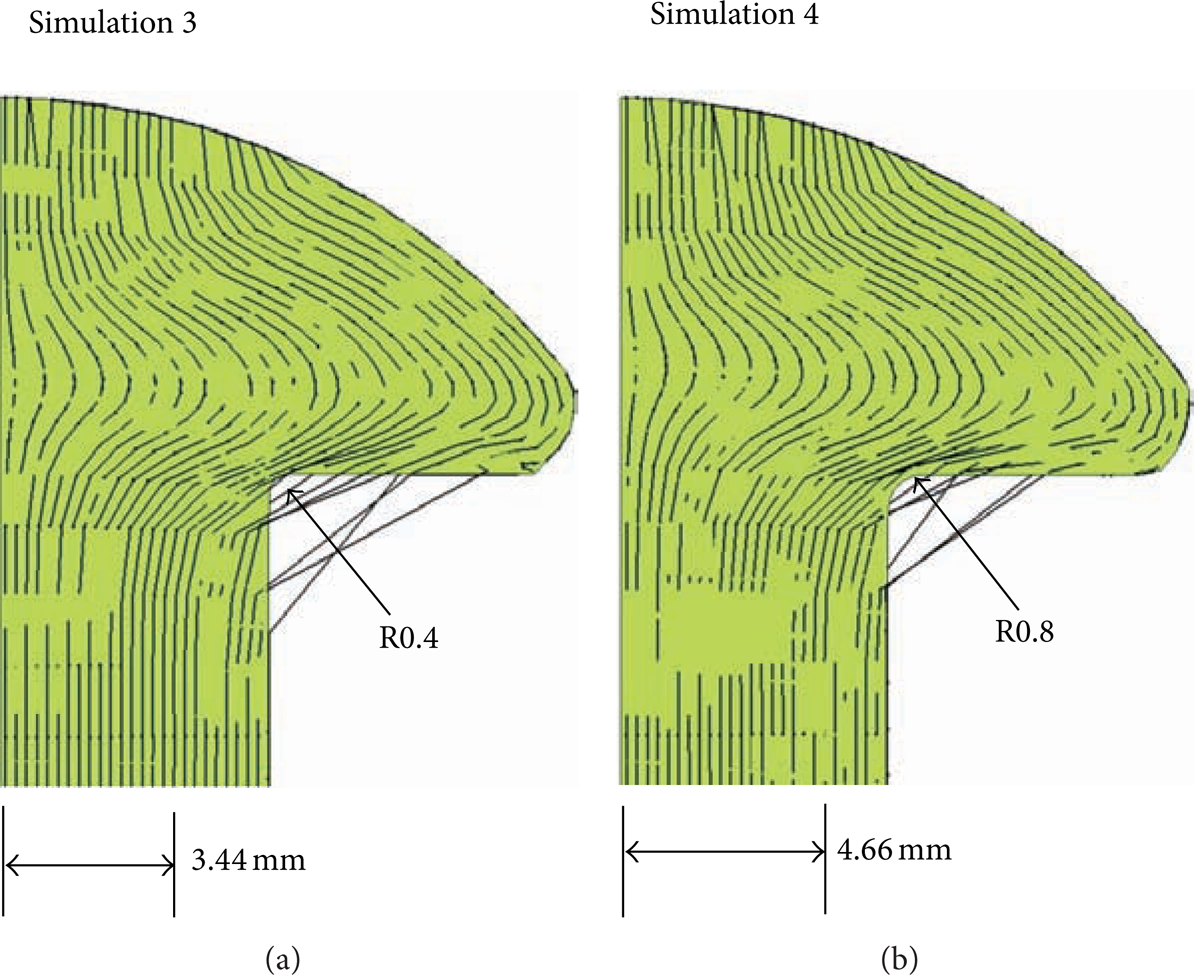
Forging stream line simulation distribution of modified forming method.
Simulation 4 (Figure 12(b)) is the simulation by setting the R-angle of dies as 0.8 mm. The result obtained from the range of intact forging stream line from the center to 4.66 mm and the ratio of the intact forging stream line are accounted for 69.0% of the cross-section area for the grip. Obviously, it changed the forming method and increased the R-angle of mold from 0.4 mm to 0.8 mm and obtained significant improvement in the result.
4. General Discussion
Since the tensile strength was only 291 MPa of finished products that were obtained from the original forming method (R = 0.4 mm), it did not reach the required standards and could not carry out the production. Thus, working personnel were directly based on their experience and changed the R-angle into 0.8 mm to conduct the trial and tensile test at that time, and the result shows that the bolt did not break under the standard stress 392 MPa and reached a qualified status. Therefore, the change in R-angles is obviously helpful to the tensile strength; that is, better tensile strengths can be obtained with larger R-angles, and such tendency is identical to the result of simulation. Similarly, this study uses the number of breakages for the forging stream line in plastic deformation to show the capability of billet for bearing the tensile strength in the end result; in addition, there is a correlation between them and the tendency is identical to the actual tensile test. Another aspect is the gap between the billet diameter and the internal diameter of dies cavity at the next stage, when the forming method has been changed, the material deformation makes the internal diameter of bolt increased, then the gap in the entire mold cavity can be reduced at the next stage. The simulation of modified forming method shows that such method can also reduce the number of breakages for the forging stream line in plastic deformation; thus it can improve the tensile strength for finished products.
Therefore, no matter which forming method or partial modification of dies dimension is, after using the simulation software to yield results, then one observes the number of breakages for the forging stream line in plastic deformation which can be used as the basis of effective comparison with the good or poor bearing tensile strengths for those finished products that were produced from various conditions.
5. Conclusions
Based on the results of aforesaid simulation analysis and actual tensile test, one has the following conclusions.
The dies with bigger R-angles can reduce the number of breakage for the forging stream line in the plastic deformation and also can obtain better tensile strength.
If the gap between the diameter of billet obtained at the previous stage and the inner diameter of dies cavity at the next stage is smaller, then the number of breakages for the forging stream line in the plastic deformation will be lesser; thus it can upgrade the tensile strength for finished products.
Conflict of Interests
The authors declare that there is no conflict of interests regarding the publication of this paper.