
Abstract
The microvibration has a serious impact on science experiments on the space station and on image quality of high resolution satellites. As an important component of the active vibration isolation platform, the maglev actuator has a large stroke and exhibits excellent isolating performance benefiting from its noncontact characteristic. A maglev actuator with good linearity was designed in this paper. Fundamental features of the maglev actuator were obtained by finite element simulation. In order to minimize the coil weight and the heat dissipation of the maglev actuator, parametric design was carried out and multiobjective optimization based on the genetic algorithm was adopted. The optimized actuator has better mechanical properties than the initial one. Active vibration isolation platforms for different-scale payload were designed by changing the arrangement of the maglev actuators. The prototype to isolate vibration for small-scale payload was manufactured and the experiments for verifying the characteristics of the actuators were set up. The linearity of the actuator and the mechanical dynamic response of the vibration isolation platform were obtained. The experimental results highlight the effectiveness of the proposed design.
1. Introduction
With the increasing requirement for higher accuracy in science activities, higher environment quality is demanded. However, the microvibration, occurring in low-frequency range, has a serious impact on science experiments on the space station or the staring image quality and gravity gradient measurement of high resolution satellites. Therefore, the vibration isolation platform used to isolate microvibration is needed to provide an ideal environment for space missions.
Passive vibration isolation, which is reliable to isolate high-frequency vibration, has a poor performance in microvibration frequency range [1]. Due to the extremely small stiffness needed to isolate such low-frequency base disturbances, active vibration isolation offers significant advantages over passive systems [2]. Moreover, the active vibration isolation has the characteristics of strong adaptability and lightweight, based on which it is feasible to realize precise pointing and clear image of new generation satellites [3]. Active microvibration isolation methods have garnered increasing attention due to their excellent properties.
Piezoelectric actuators and maglev actuators are excellent in active vibration isolation field. Piezoelectric actuators can afford high force and stiffness but can only obtain micron-sized displacement [4]. In order to isolate a broader frequency bandwidth, large stroke is necessary. While the maglev actuator can produce larger stroke [5] and desirable isolation, performance is shown even in the frequency range below 0.1 Hz [6]. Maglev technology has been proven to be one of the most promising methods in isolating vibration in frequency range below 5 Hz [7], which can also be used to realize the disturbance free payload due to its noncontact characteristics [8].
Liu et al. [9] designed a voice coil motor used in ultraprecision motion stages and an improved magnetic equivalent circuit model was built to optimize the voice coil to enhance the dynamic response. The method is worth considering, but it is designed for the special application. Hsu and Tzou [10] designed a cylindrical voice coil motor for autofocusing digital camera. It is more suitable to be applied in small size and light mass occasion. Kim et al. [11] designed a cylindrical voice coil motor for a vibration isolation system and a sliding rode is adopted to keep the linearity of the magnetic flux density. However, the construction of the actuator for a vibration isolation platform is complex. Chen et al. [12] designed a voice coil motor with a larger stroke and a larger volume, which can be used as a vibration absorber for a rotating machine. Banik and Gweon [13] designed a compact voice coil motor and standard gradient descent algorithm is used to minimize cost function. However, the structure of the actuator is complicated and there is no prototype to prove the feasibility. Kim et al. [14] designed and optimized a voice coil motor using the Halbach magnet array; it can enhance the magnetic flux density but the total weight of the actuator will be increased.
This paper aims to design a good linear maglev actuator to conduct active vibration isolation for different-scale platform. Finite element method (FEM) simulation is performed to grasp the fundamental characteristics of the actuator. In order to gain a superior structure of a maglev actuator, parametric design method is adopted and a designing program is developed. Then genetic algorithm is used to minimize the coil weight and the heat loss. The prototype of the active vibration isolation platform for small-scale payload is manufactured and experiments are set up to verify the characteristics of the actuator.
2. Design of the Maglev Actuator
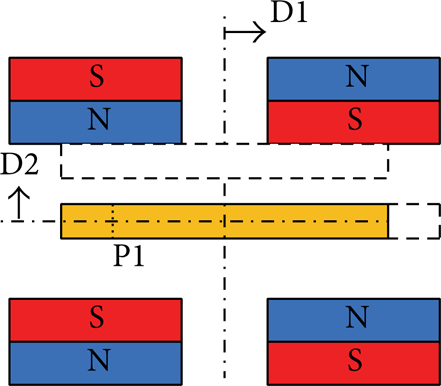
As the main part of an active vibration isolation platform, the characteristics of the actuators are very important to the performance of the platform. The maglev actuator with good linearity would be preferable to improve the isolation performance and simplify the control strategy. The diagram of the proposed actuator based on the Lorentz force is shown in Figure 1. It is composed of two couples of opposing bar magnets with yoke as the support frame and a coil with its holder. The coil is located within the boundaries of the permanent magnets to obtain uniform magnetic flux density. The Lorentz force is developed on two straight edges of the coil and each actuator has only one degree of freedom (DOF). The actuator in Figure 1 will produce a horizontal force. A vertical force is achieved by simply rotating the actuator through 90°. In order to realize the multi-DOF control, several actuators are adopted together to conduct the motion and rotation.
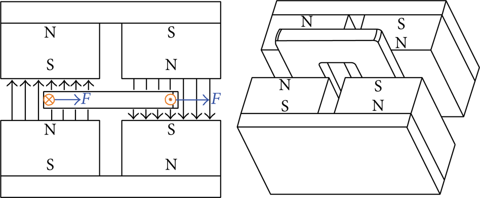
Diagram of the actuator structure.
Nonferrous material, such as the aluminum alloy, can be utilized as the holder of the coil, which can avoid hysteresis, eddy current losses, and nonlinear characteristic of ferromagnetic materials [15]. In addition, the relative permeability of aluminum alloy is estimated to be 1.0, which is equal to that of air. And pure iron can be served as the yoke to channel the magnetic field, whose relative permeability can reach to several hundreds or more.
In order to obtain good mechanical performance, the basic characteristic of the actuator should be studied beforehand. As can be seen from the analysis of FEM simulation in Figure 2(a), a strong and relatively uniform field in the working area of the coil is created. And it can be seen from Figure 2(b) that the magnetic flux density is almost constant within the boundary of the permanent magnets. Once the coil exceeds the boundary, the magnetic flux will decrease greatly. If the yoke is not saturated, the magnetic flux leakage can be neglected.

Characteristics of the maglev actuator.
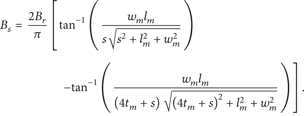
When there is a random vibration, the location of the coil would deviate from the center location of the permanent magnets. To confirm the relationship between the magnetic flux density and the relative position of the magnets and the coil, simulation results of the position change are presented, which will be helpful to understand the properties of the maglev actuator in a random circumstance.
The initial location of the coil is at position P1 in Figure 3. The coil is kept stable without any disturbance at this point. When there is a random disturbance, the coil would move randomly towards the magnet groups. D1 and D2 in Figure 3 represent the moving direction of the coil. According to the FEM simulation, the magnetic flux density through the coil at any position within the boundaries of the magnets is shown in Figure 4. A slight change (2.9%) of the magnetic flux density happens when the coil vibrates. In addition, it can be seen that the position change of the coil along D1 has almost no impact on the magnetic flux density and the location change of coil along D2 has a negligible effect on the magnetic flux density.
Position change between magnets and coil.

Influence of D1 and D2 on the magnetic flux density.
According to the Lorentz force principle, the nonlinearity of the maglev actuator is associated with the nonlinear magnetic flux density. If the magnetic flux density is constant, the Lorentz force is directly proportional to the current. By regulating the current, the desired force can be obtained. From the simulations above, it can be concluded that the magnetic flux density can be regarded as a constant value within the moving scope of the coil. So the proposed maglev actuator in the paper is of good linearity.
2.1. Parametric Design of the Actuator Structure
Dimension parameters of the permanent magnets and the coil are shown in Figure 5. t m , w m , and l m are the thickness, width, and length of the permanent magnet, respectively. Wcoil, tcoil, wcoil, and lcoil are the sizes of the coil. d1 is the distance between two permanent magnets on each side. The actuator force, the coil weight, and the total heat dissipation all depend on the dimensions of the structure. The magnetic flux density in the air gap, where the coil is located, is affected by the dimensions of the magnet and the structure of yoke. In order to simplify the calculation process, the yoke is not considered in this design. Once the magnets’ dimensions are confirmed, the dimensions of the yoke can be determined.

Definition of geometry parameters.
In the model, there are a couple of permanent magnets on each side, so the ideal magnetic flux density in the center of the air gap can be calculated by the following equation, where B r is the remanence and s is the gap distance:
Properties of the permanent magnet material are important to the magnetic levitation system. Rubidium iron boron permanent magnets exhibit high coercive and remanence and offer stable performance at high temperature, which can not only increase the magnetic force but also reduce the degaussing effect. N38H was chosen to be the permanent magnet, whose remanence is 1.23T. As shown in Figures 6 and 7, the magnetic flux density in the air gap, where the coil is located, is affected obviously by the dimensions of the magnet groups.

Influence of t m and g on B.
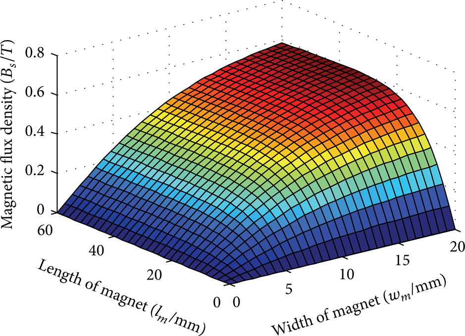
Influence of w m and l m on B.
The relative position of the magnets and the coil is shown in Figure 8, where x1 × x2 × x3 are the maximum dimensions of the actuator, d2 is the stroke of the actuator, ηpack is the filing ratio of copper alloy, and p and q are the fundamental sizes of the coil frame. Boundary dimensions constraints are favorable to gain the compact size.

Relative position of magnets and coil.
Based on the working principle of the maglev actuator, when there is any random vibration, the gap distance should be large enough to avoid the stator crashing into the floater during the response time. Therefore, the gap distance should be longer than the sum of twice the maximum vibration amplitude and the thickness of coil. Assuming that the coil holder has a total thickness of c, the relationship between gap distance and thickness of coil can be written as s ≥ tcoil + 2d2 + c.
As the model of the actuator is symmetric, the relative position relationship between the permanent magnets and the coil is designed by the following conditions: w m ≥ wcoil + 2d2, lcoil ≥ l m + 2wcoil + 2d2, and Wcoil ≥ 2wcoil + d1 + 2d2. To get a compact size, the design is made according to the minimum boundary conditions.
According to the equation of magnetic flux density, the Lorentz force can be written as

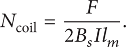
Then the number of turns of the coil can be calculated by
As the gap distance is s and the stroke of the actuator is d2, the layers of the coil L could be written as

The number of turns per layer T is

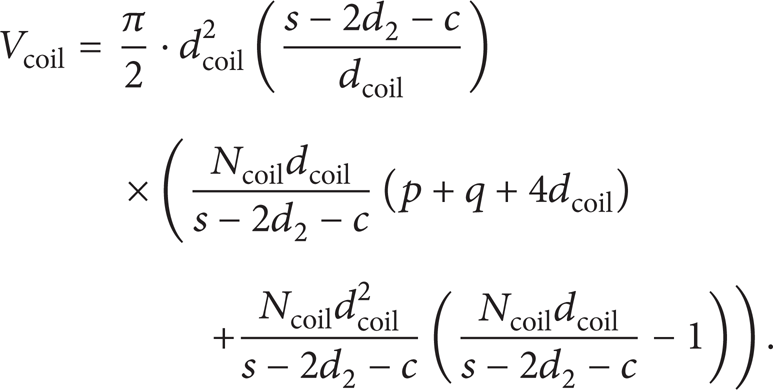
The volume of the coil Vcoil can be written as
Therefore, the coil weight mcoil is

where ρ is the density of copper wire.
The heat dissipation Q is

A design program for the maglev actuator was developed by MATLAB. Design targets and initial parameters should be input beforehand. Then according to the Lorentz force equation, the relative position relationship between the permanent magnets and the coil, the sizes of the coil, the Lorentz force, the coil weight, and the heat dissipation can be output.
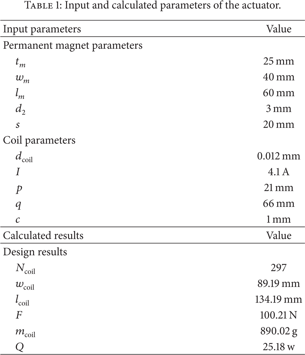
Assuming a 100 N Lorentz force is needed for each maglev actuator. The input parameters are listed in Table 1. According to the design program, the parameters of maglev actuator can be obtained in Table 1. The design program provides a convenient way to obtain the dimensions of the proposed actuator.
Input and calculated parameters of the actuator.
2.2. Multiobjective Optimization of the Maglev Actuator
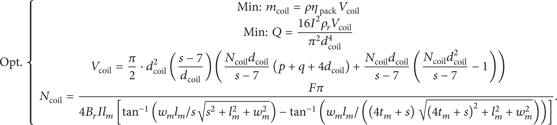
In order to obtain better mechanical properties, the optimization of the actuator structure is essential. In accordance with the maximum boundary conditions of the actuator, several boundary constraints can be written as follows: 2w m + d1 − x1 ≤ 0 and 2t m + s − x2 ≤ 0, lcoil − x3 ≤ 0. Appropriate sizes of permanent magnet and gap distance should be chosen firstly. As the magnetic flux density increases with the increasing of permanent sizes, it should maximize the magnet sizes as much as possible. The permanent magnet of the proposed actuator has a maximum size of 30 (mm) × 50 (mm) × 90 (mm). Optimization objectives are listed in the following equation:
The influence of the gap distance and the number of turns on the Lorentz force is shown in Figure 9. It can be seen that the Lorentz force reaches to a maximum value and then decreases as the gap distance increases. Besides, the actuator force is proportional to the number of turns. As the increment of the number of turns will lead to the increase of the coil weight, the gap distance and the number of turns should be chosen reasonably to satisfy the requirement of a given force without increasing the coil weight greatly.
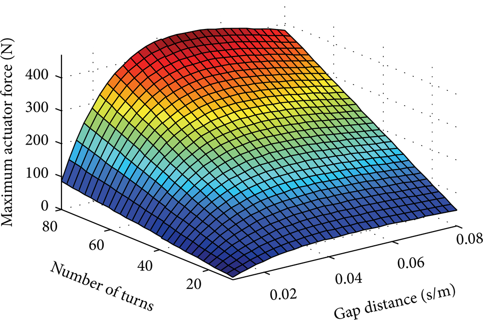
Influence of the gap distance and the number of turns on the Lorentz force.
For a 100 N Lorentz force, an acceptable gap distance for the minimum coil weight can be found, as exhibited in Figure 10. And a minimum value of heat dissipation can also be obtained at the same gap distance for the minimum coil weight.
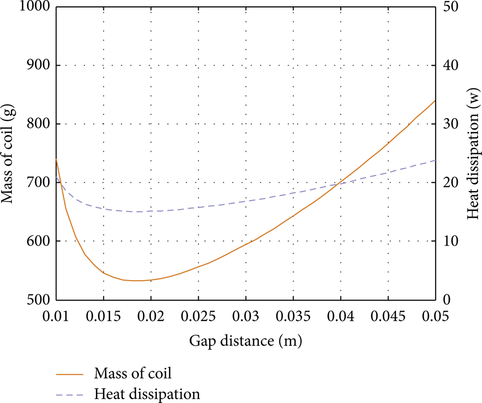
Minimum value of the coil weight and the heat dissipation.
As the layers of the coil and the turns per layer should be integers, the algorithms in the MATLAB optimization toolbox, like fminunc and fminsearch (the unstrained nonlinear minimization), can only achieve a local optimization. However, the genetic algorithm can find a globally optimal resolution efficiently. By using the genetic algorithm, the optimum gap distance can be solved out, at which the minimum coil weight and heat dissipation can be calculated. On the condition of the design target, when the gap distance is 19 mm, the coil weight and the heat dissipation will achieve the minimum value. Then all the parameters about the maglev actuator can be obtained.
Optimized results and initial values of the actuator are displayed in Table 2. The optimized actuator has better mechanical properties than the initial one. The optimized coil weight (567.76 g) is superior to the coil weight (890.02 g) based on initial values. What is more, the heat dissipation after optimization (15.06 w) is less than the initial value (25.18 w). In a microgravity environment, the Lorentz force needed is much less than the one needed on the ground, and the coil weight and heat dissipation will be less too. The analysis of the design and optimization of maglev actuator in this paper is meaningful to conduct experiments on the ground, where a constant acceleration 1 g exists. Optimization of the maglev actuator is beneficial to improve the mechanical properties and to enlarge its application on the space and the ground.
Comparison between optimal results and initial values.

3. Mechanical Design of the Active Vibration Isolation System
The complete system with maglev actuators for small-scale payload is shown in Figure 11. The stator, which is in direct contact with the disturbance, is composed of one base plate and four double side plates. Several permanent magnet groups are embedded into the inner and outer side plates. One crown sheet and four side plates constitute the floater. Eight rectangle coils are inserted in the side plates of the floater, of which the location corresponds to the location of permanent magnets. In the constant magnetic field produced by permanent magnets, the Lorentz force with different magnitudes and directions can be obtained by regulating the coil current. In a microvibration environment, the flexible Lorentz force is used to counteract the disturbance to guarantee that a payload is least affected. All plates are made of aluminum honeycomb board to lighten the system. In addition, a retaining mechanism is used to fasten the floater during launching and in orbit and a position-limit mechanism is adopted to keep the floater and the payload escaping from impacts caused by huge random disturbances. The only disturbance sources from the stator to the floater are the umbilical cords that provide power for the sensing devices and transmit signal data from these devices.

Vibration isolation platform for small-scale payload.
The configuration of the actuators and the driving characteristic of the small-scale payload platform with six DOFs are shown in Figure 12. The vertical displacement and pitching motion are produced by actuators 1, 3, 5, and 7. Actuators 2 and 6 are used to produce the horizontal movement in the x-axis direction and rotation around the z-axis. And actuators 4 and 8 are applied to provide horizontal movement in the y-axis direction and rotation around the z-axis. Each module can be considered as a self-sufficient single-axis vibration isolation system.

Direction and distribution of active control force of actuators.
For large-scale payload, such as the telescope and the satellite, it is impossible to develop a huge vibration isolation platform to support that for it takes up too much space. Multipoint layout support of maglev actuators may be an effective way to solve the problem. As shown in Figure 13, only several actuators are needed to levitate the whole payload. One point to highlight is that these actuators may have a total of five or six DOFs to maintain the payload for an ideal attitude and position.

Schematic diagram of multipoint supportive method for large-scale payloads.
4. Performance Verification of the Vibration Isolation Platform for Small-Scale Payload
The prototype to isolate vibration for a small-scale payload was manufactured and eight actuators were assembled as shown in Figure 14. The experimental setup was exhibited in Figure 15. Laser displacement sensors (LDS) were chosen as the device to measure the displacement of the floater.

Prototype of the vibration isolation platform for small payload.

Experimental setup.
4.1. The Linearity of the Maglev Actuator
In order to verify the linearity of the maglev actuator, experiments on the relationship between the force and the current have been carried out. Payload with different mass is put onto the platform and the appropriate current was regulated to levitate the payload stably. It should be carried out on the precondition that the boundaries of the coil do not exceed the boundaries of permanent magnets and the effective coil length is kept unchanged.
The current was recorded when different masses were placed on the floater and levitated stably. According to the data, a curve can be displayed in Figure 16, which is estimated to be a straight line. The line represents that the force is proportional to the current at any coil location beyond the precondition. So the experiment verifies that the magnetic flux density can be considered as a constant value in the working scope of coil and the maglev actuator has good linearity.

Relationship between the force and the current.
4.2. Mechanical Response of the Vibration Isolation Platform
The mechanical response of the system can be obtained by the curve of the step response. The experiment was conducted by making the floater reach to its stable state when a given current was input. The LDS read the displacement of the floater by 20 ms at a time. The data was recorded and a step response curve was obtained in Figure 17.

Mechanical response of the platform.
The tolerance zone is assumed to be ± 4% of the steady-state value. It can be seen from the curve that the transient time is 0.49 s. That means the platform needs a 0.49 s time to reach the steady state for the mechanical inertia of the system. The curve has no oscillation which shows that the damping capacity is good. To obtain good isolation performance, feedback control would be added on the vibration isolation system. The design of the controller would be discussed in the following papers.
5. Conclusions
In this paper, the maglev actuator based on the Lorentz force was designed to obtain good linearity. FEM simulation results showed that the actuator can produce a strong and uniform magnetic flux density and the magnetic flux density within the boundaries of the permanent magnets can be considered as a constant value. Parametric design of the actuator was conducted and genetic algorithm was used to minimize the coil weight and the heat dissipation. For a given 100 N force, the optimum gap distance was found at 19 mm and an actuator with minimum coil weight (567.76 g) and heat dissipation (15.06 w) was obtained. The structures of the microvibration isolation platform for different payloads were designed and the prototype for isolating vibration for small-scale payload was manufactured to test the characteristic of the actuator and the mechanical property of the platform. Experiment results prove that the maglev actuator has good linearity and the platform has good damping capacity. The design and optimization of the proposed actuator will be helpful to enlarge the application of the vibration isolation platform on the space and on the ground.
In the future, more work on the realization of the system function will be carried out. The feedback controllers, such as the three closed-loop PID controllers and the nonlinear feedback controllers, will be researched for the vibration isolation system to make sure that the magnetic levitation vibration isolation platform can achieve excellent isolation performance in microvibration frequency range.
Conflict of Interests
The authors declare that there is no conflict of interests regarding the publication of this paper.
Footnotes
Acknowledgments
This study was supported by College Discipline Innovation Wisdom Plan China (Grant no. B07018) and Self-Planned Task (Grant no. SKLRS201301B) of State Key Laboratory of Robotics and System (HIT).