
Abstract
Since the inlet and outlet of hidden ceiling fan are almost located at the same Plane; thus, an improper housing may cause inhale-return phenomenon which significantly affects its power consumption and performance. In this study, a comprehensive investigation by numerical and experimental techniques was used to predict and identify the flow pattern, airflow rate, efficiency, and noise for ceiling fans with different design parameters. The results showed that the unique inhale-return phenomenon happens for an inappropriate housing. Several key parameters, such as fan guard, housing ring, inlet-to-outlet area ratio, and blockage height, are evaluated for finding out the criterion to avoid the inhale-return flow. Consequently the study finds that fan guard changes the airflow to a wider distribution with a lower velocity. A minimum blockage distance and a maximum height of ring-plate are set at 80 mm and 30 mm, respectively. Also, it is suggested that the inlet area must be bigger than the outlet area. Moreover, all the parameters show the same trend under various rotational speeds. In conclusion, this systematic investigation not only provides the fan engineer's design ability to avoid the inhale-return phenomenon, but also the predicting capability on its aerodynamic and acoustic performances.
1. Introduction
Ceiling fans are mainly employed to circulate or mix air within a space and provide local air movement for enhancing the thermal comfort of people. In most tropical countries, ceiling fans are extensively used to create an indoor breeze, improve the air distribution, and increase the feeling of comfort via cooling effect which is provided by fans. From the economic viewpoint, ceiling fans have the features like low investment cost, simple construction, easy to install, and no need to maintain. In particular, they consume a relatively low amount of energy compared to the air conditioning units, and therefore are used on a large scale worldwide. Despite the widespread use of air conditioning units, it has not replaced the ceiling fan but complemented its usage.
Rohles et al. [1] studied the effectiveness of ceiling fans in enhancing comfort experimentally by varying temperature and air velocity in an environment chamber equipped with a ceiling fan. The results showed that an air flow from a ceiling fan with velocity between 0.5 and 1.0 m/s compensates for a 2.8°–3.3°C temperature change. James et al. [2] showed that the addition of ceiling fans in an air-conditioned room can lead to substantial energy saving, if ceiling fans are used in conjunction with higher thermostat set points. Sonne and Parker [3] performed a similar energy-saving investigation through the field tests in two occupied Miami homes. A test room was setup to measure the ceiling fan's power consumption, rotational speed, and airflow underneath the fan. Results revealed that the field monitoring work indicates significant potential benefits from consumer education on ceiling fan use. Aynsley [4] reported that large ceiling fans offer an effective way to mix the air layers so that air temperature becomes uniform between floor and ceiling. Destratification is the most important issue in spaces with high ceilings, such as industrial buildings, warehouses, commercial buildings, and particularly atria. Winter energy savings from destratification of up to 30% have been achieved in warehouses with large ceiling fans and ceiling heights from 10 to 15 m.
For the increasing efficiency, a comparative study of commercially available ceiling fans and a high-efficiency fan is given by Schmidt and Patterson [5]. This new fan consists of four blades with tilt angles varying over the length of the blade to adjust the angle of attack for different speeds at different radii. The air velocity was measured by means of a hot-wire anemometer in a horizontal plane located 1 m below the blades. By integrating the air velocity over the measured point, the power in the airflow rate can be calculated. Parker et al. [6] used a numerical analysis to study the effect of blade geometry on the flow, based on which airfoil blades were designed. According to the report, the air moving efficiency was increased by 86% at low speed and 111% at high speed, respectively. Jain et al. [7] utilized smoke from thick incense sticks to visualize the flow field that was created by the ceiling fan inside a closed room. Two horizontal planes were chosen to measure the velocity. Also, significant improvements are observed on adding winglets or spikes at blade tips, which should be attributable to the disruption of tip vortex activity.
With assisting by numerical procedure, Ho et al. [8] used the steady, two- and three-dimensional numerical simulation for a person standing in a room to calculate the airflow and heat transfer. The results showed that, as the air speed from the fan increases, thermal comfort significantly shifts toward the cooler scale to allow a higher supply air temperature or higher heat load while maintaining the same comfort level. With regard to the studies of flow pattern induced by ceiling fans, after experimentally investigating the flow, Bassiouny and Korah [9] used mathematical and computational fluid dynamics (CFD) models to predict the flow pattern induced by a ceiling fan. The results showed that increasing the fan rotational speed results in increasing the local downward velocity. Zhu et al. [10] performed a numerical modeling method for the indoor environment with ceiling fans and upper-room ultraviolet germicidal irradiation (UR-UVGI) fixtures. The numerical modeling deployed steady CFD calculation with a rotating reference frame to simulate the rotating fan blades. According to the validation results, the CFD model correctly reproduced the air movement induced by the rotation of ceiling fan for UR-UVGI. From previous researches, it is clear that the proper use of the ceiling fan can improve the efficiency of air movement, thermal comfort, and energy savings.
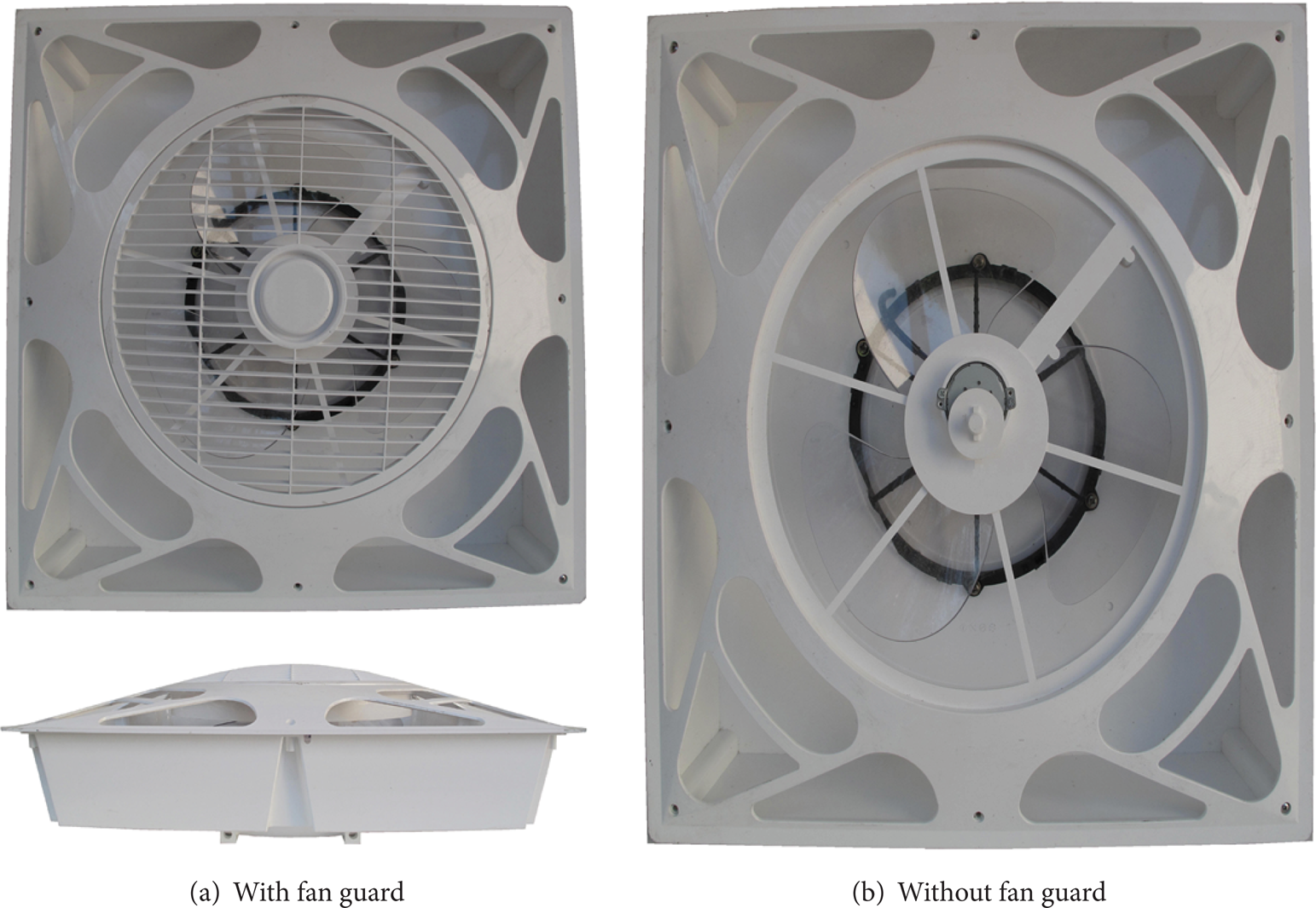
In this study, a hidden ceiling fan is the upgraded evolution which inherited all the characteristics from traditional ceiling fans, as shown in Figure 1. The hidden ceiling fan hides its configuration almost behind the ceiling floor. Obviously, this design can prevent the explosion of rotational blades to occupant's space and save the required space for installation. Furthermore, this arrangement eliminates the sense of space compression and secures the security. According to survey, Alias et al. [11] showed that the head injury by fan blade included jumping on the upper bunk of a bunk-bed, climbing on a ladder, climbing up onto a table, and being lifted by an adult. This study implies that the ceiling fans without an enclosing housing may cause occupant's injury and burden the occupant's mind with sense of space compression.

Types of the ceiling fans.
The hidden ceiling fan has a lot of advantages with an enclosing housing, but its housing must be evaluated thoughtfully. Because the majority part of hidden ceiling fan is embedded in ceiling floor, the enclosing housing will be needed to surround the axial-flow fan as in Figure 1(b). Once the enclosing housing is created and hidden behind the ceiling floor, the air flow is inhaled from inlet and is expelled to outlet by an axial-flow fan. Meanwhile, the air flow will pass though the horizontal plane of ceiling floor which the inlet and outlet are located at almost the same plane. Thus, the air stream passes though the inlet and outlet can be mutually affected when the enclosing housing is not designed properly. Consequently, instead of flowing downward to the floor, the discharge air flow via outlet will directly return to the fan through the fan inlet. This negative effect due to the presence of the flow resistance inside enclosing housing is hereafter referred to as the inhale-return phenomenon. This inhale-return phenomenon affects the induced flow performance of the hidden ceiling fan. Hence, the flow pattern features induced by hidden ceiling fans are very significant and need to be understood. Therefore, an integrated numerical and experimental scheme is developed in this research for design of a new hidden ceiling fan without the inhale-return phenomenon.
As mentioned in previous studies, observing the flow pattern induced by the ceiling fan is essential for improving its performance. Especially, the flow pattern about inhale-return phenomenon that happened in the hidden ceiling fan is unique. However, no research focuses on the inhale-return phenomenon of the hidden ceiling fan. It is obvious that the path of air stream may be blocked when enclosing housing is improperly designed; hence, the fan performance might be diminished seriously. In practical applications, there is a substantial demand existed for fan engineers to realize this phenomenon in detail. As a consequence, this study not only investigates the factor of fan performance systematically by experimental and CFD means but also the corresponding variation on the design of enclosing housing is evaluated.
2. Numerical Scheme
This study simulates the complex flow patterns for the hidden ceiling fan by utilizing the commercial computational fluid dynamics (CFD) software Fluent [12] to solve the fully three-dimensional incompressible Navier-Stokes equations with the standard k − ε turbulence model. Also, the Semi-Implicit Method for Pressure-Linked Equations (SIMPLE) is implemented to solve the velocity and pressure coupling calculation for steady cases. In addition, this model also adapts the multiple reference frame (MRF) mode to deal with the rotating fluid inside the fan. MRF mode simulates the rotating fan to produce the energy of airflow which influences the entire flow pattern in the selected room.
Hence, the flow visualization under each operating parameter can be performed. The predicted outlet flow patterns with various airflow rates on different combinations of design parameters can be obtained and used to determine the fan performance. Also, the airflow rate and required torque at each operating speed can be calculated using this numerical procedure. The calculated efficiency index can be therefore be determined by

The product of calculated torque (Thub) and rotational speed (ω) is the fan input energy applied to the fluid. Furthermore, an efficiency index was attained by dividing the total volumetric flow rate as the fan input energy.
2.1. Governing Equations
All kind of flowing fluid problems are determined by physical principles, which are expressed in conservative form for mathematical description. They are mass equation (continuity equation) and momentum equation. Moreover, as the fluid is under the turbulent condition, additional turbulent equation is incorporated with the governing equations. The continuity and momentum equations in conservation form are expressed as follows.
Continuity conservative equation
Here u i is the velocity, ρ is the density, and S m is the source term.
Momentum conservative equation

where p is the static pressure, τ ij is the stress tensor, and ρg i and F i are the gravitational and external body forces, respectively. Also, the stress tensor is expressed by

where μ is the viscosity coefficient and δ ij is the kronecker delta. The second term on the right hand side is the effect of volumetric dilation.
For a coordinate system rotating in a steady angular velocity, the equations of motion are solved in a rotating reference frame that results in additional terms to represent the acceleration in the momentum equations [13]. The relative velocity

Here,
2.2. Reynolds-Averaged Navier-Stokes Equation
When the fluid inertia affects the flow field more significantly than the fluid viscosity, the flow develops into a turbulent flow. Turbulent flows are characterized by fluctuating velocity field which causes many eddies due to this fluctuation. In this study, the k − ε turbulence model is utilized to solve the Navier-Stokes equations. With respect to the incompressible flow and no source condition (S m is zero) under the steady-state, the governing equations are


Note that (7) is called the Reynolds-averaged Navier-Stokes (RANS) equation, where the Reynolds stress
Here μ t is turbulent viscosity and δ ij is Kronecker delta.
The advantage of this approach is the relatively low computational cost associated with the computation of the turbulent viscosity. The k − ε model computes the turbulent viscosity as a function of turbulence kinetic energy k and turbulence dissipation rate ε:

where G K = μ t (∂u i /∂x j + ∂u j /∂x i )(∂u i /∂x j ) is the turbulent kinetic energy generated by the mean velocity gradients. C1ε, C2ε, Cμ, σ k , and σε are model constants with the following empirically derived values: C1ε = 1.44, C2ε = 1.92, Cμ = 0.09, σ k = 1.0, and σε = 1.3, respectively [14].
3. Experimental Program and Apparatus
The hidden ceiling fans available in the market have a tendency to install inside the ceiling floor and to design as thin as possible. This indicates that the whole flow passage inside the enclosing housing has to compress and hide inside the ceiling floor. In other words, the overall flow resistance increases even worse to block the air stream. This consequence can diminish the flow rate and consume more energy. Obviously, this unfavorable effect can influence the fan's flow pattern for the cooling of occupant. Within a crowded enclosing housing, the complex problem of flow resistance inside the hidden ceiling fans needs to improve.
3.1. Experimental Program
Figure 2 illustrates the flow chart of this study; the evaluation scheme of hidden ceiling fan includes the performance enhancement, efficiency evaluation, and noise analysis. For investigating the flow pattern and fan performance, the parametric study chooses five parameters which are fan guard, blockage distance, housing-ring height, inlet-to-outlet area ratio, and rotational speed. Figure 3 indicates these parameters setting of the disassembled hidden ceiling fan.

Flow chart of the integrated fan-evaluation investigation.
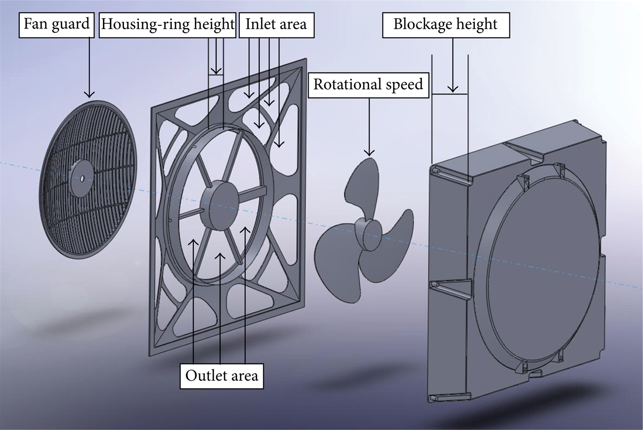
Parameters of the disassembled hidden ceiling fan.
Firstly, the fan guard attaching to the hidden ceiling fan is applied for inducing a uniformly downward airstream. With the aid of fan guard, the flow pattern can become a uniform exit flow for meeting the requirement of occupant demand, but it also increases the flow resistance that can affect the airflow rate, power consumption, and noise characteristics. Recently, the housing of hidden ceiling fan has the tendency of becoming thinner for installing easily inside the ceiling floor. With a thinner housing, the length between the fan inlet and the blockage plate is shorter and therefore reduces the total space for airflow to pass through. Subsequently, the overall system resistance increases and causes an insufficiently vertical downward airstream from the fan blade. For investigating this complex problem, a plate is added to simulate the flow due to the narrow spacing between blockage plate and fan. This situation is similar to placing a plate on the top of the fan at a certain distance. Also, by altering this distance from the fan, it is possible to judge the effect of fan performance due to various thinner housings.
In addition, the housing ring separates the upward moving inlet air from the downward outlet air; thus, a higher housing-ring is more appropriate for this purpose. However, it is also easier to obstruct the flow passage and increase the flow resistance. Next, the inlet-to-outlet area ratio is considered as an important factor here since the fan outlet is located in the central region and is surrounded by the inlet area. Clearly, a large inlet area can intake more airflow, but it may have interaction with the exit airstream. In contrast, the small one can reduce the housing size but it also can increase the flow resistance. Thus, a proper inlet-to-outlet area ratio needs to be determined.
Moreover, for improving the fan characteristics, all the parameters are experimentally and numerically examined by this integrated means systematically. The focus is set on the variable flow resistances which can affect the flow pattern distribution, fan efficiency, and noise level. In this study, experimental measurement, including airflow rates and noise tests, were executed via a hot-wire anemometer and in a semianechoic chamber, respectively. Numerically, the simulated calculation and visualization analysis were carried out using the CFD tool. Also, the numerically calculated airflow rates are validated by comparing them with the corresponding experimental measurements.
3.2. Experimental Apparatus
To evaluate the modification results, this study measures the performance and noise of the hidden ceiling fan via the standard procedures based on CNS-597 [15] and CNS-8753 [16]. The test fan, as plotted in Figure 4, is a 356 mm in diameter axial-flow fan with a housing of 582(L)*582(W)*192(H) mm. The measurement setups are explained in the following subsections.
The enclosing housing for the ceiling fan.
3.2.1. Performance Measurement Setup
A performance test system was setup for recording the power, rotational speed, and airflow of the hidden ceiling fan. A digital hot-wire anemometer, with an accuracy of 0.03% and measurement range up to 30 m/s scale reading, was mounted on a tripod to take air-velocity measurements. A precision digital watt meter (with a resolution of 0.1 W) was adopted to measure the power consumption, and a noncontact photo tachometer (with a 0.05% accuracy and an 1 rpm resolution) was utilized to measure fan speed.
As indicated in Figure 5(a), the hidden ceiling fan was mounted in a large room with the size of 15(L)*15(W)*3(H) m. The hidden ceiling fan was mounted on the ceiling floor in the center of the room. The air velocities were measured by means of a hot-wire anemometer with the measuring plan below the ceiling floor by 1 m. The test location begins at the fan axis r = 0 and then move radially outward on this measured plane by placing each point at 50 mm increments. Basically, points on a straight line can form several circles (see Figure 5(b)), and each circle is divided every 30 degree to form the 12 measuring points, which is used to take account the nonsymmetric flow of hidden ceiling fan.

Sketches of test setup and measuring points.
In addition, data for each measured point was recorded for 2 minutes and averaged to attain the mean downward velocities. The measurement readings were undertaken over the entire horizontal plane below the fan outlet until the air velocity becomes almost undetectable (below 0.1 m/s). By integrating the air velocity over the measured radially plane, the flow rate (Q) can be obtained. Also an efficiency index was produced by dividing the total volumetric flow rate to the measured motor wattage (cfm/W).
Consider

3.2.2. Noise Measurement Setup
This experiment measures the sound pressure levels using a RION NL-14 portable sound level meter (SLM) and an AND AD-3524 FFT frequency analyzer. The sound pressure creates analog signals in SLM microphone; these signals were then fed into the FFT analyzer to generate the noise characteristics. Additionally, the consistency and calibration of these devices are verified by a transducer-type calibrator (94 dB at 1 kHz) both before and after each measurement. The noise at fan outlet is measured by employing the CNS-8753 standard. As shown in Figure 6, the semianechoic chamber offers an appropriate test environment.

Measuring positions of microphone inside the semianechoic chamber.
4. Parametric Study on Fan Characteristics
The hidden ceiling fan at various operating parameters is analyzed with the aid of this integrated experimental and numerical effort. The following subsections discuss the performance analysis, efficiency estimation, and noise spectrum analysis for the hidden ceiling fan.
4.1. Performance Analysis
For investigating the characteristic of the hidden ceiling fan, Table 1 lists the parameters settings of the cases considered in this study. For demonstrative purposes, fan performance is evaluated under the same rotational speed (1, 200 rpm, median speed) for both numerical simulation and experimental measurement. Figure 7(a) compares the volume flow rates for different parameter settings. It is observed that the experimental airflow rate shows the same trend as numerical prediction. When data was measured below the fan discharge by 1 meter, the experimental airflow rate is smaller than CFD's by roughly 6∼12%. This deviation is reasonable due to the experimental accuracy and the simplified numerical model.
Case description and classification.


Performance comparison of all fan cases.
Figure 7(b) illustrates the calculated performance results for various parameters and rotational speeds, including low (1, 000 rpm), medium (1, 200 rpm), and high speed (1,400 rpm). The similar trend is observed for all speeds considered here. Noticeably, the airflow rates for cases C50, C70, and D92 are approaching zero for different rotational speeds since the inhale-return phenomenon appears. This implies that inhale-return phenomenon is independent to rotational speed.
4.2. Fan Guard Setting
Figure 8 demonstrates the calculated velocity patterns of the ceiling fan with and without fan guard for the planes below the blade by 0.25 m, 0.5 m, 0.75 m, and 1 m. Figure 8(a) shows that the fan with guard induces the flat-distribution airflow with the lower velocity magnitude. On the contrary, fan without guard generates the narrow-distribution airflow with a higher velocity as shown in Figure 8(b). Notice that all the velocities below the 0.1 m/s on the horizontal were not taking into account during the experimental measurement. Also, by observing Figure 7(a) for test and CFD results, a 10 cfm reduction is found for fan with the guard (case A).

Comparison of flow pattern induced by fan guard.
4.3. Blockage Distance
For evaluative purposes, several blockage distances are selected to discuss the influences of various resistances on fan system. Figure 9 shows the schematics of blockage distances which are denoted as cases B80, B60, B40, and B20. As indicated in Figure 7, the numerical airflow rates at median speed for various blockage distances are case B80 (1365 cfm), case B60 (1308 cfm), case B40 (1296 cfm), and case B20 (1230 cfm), respectively. The results show that less airflow rate is produced for a shorter blockage distance.

Schematic of the blockage distance.
Furthermore, to obtain an overall understanding, flow visualization is carried out numerically at several important cross-sections to reveal the distinctive flow patterns under different parameters of fan system. Figure 10(a) shows the detailed flow filed on the axial cross-section. It indicates that the incoming air flows into the fan inlet, makes the U-turn enter the fan rotor, and then passes through the fan discharge to reach the measuring plane. Figure 10 shows the enlarged views when the blockage plate is placed at 80 mm, 60 mm, 40 mm, and 20 mm on the top of housing. Apparently, once the airflow channel was suppressed by blockage plate, the flow rate is slightly reduced to a lower limit at 83.3% of that from fan without the blockage plate. Furthermore, the blockage effect would not result in the inhale-return phenomenon; even the flow is suppressed within the narrow channel.

Enlarged velocity distributions for various blockages.
4.4. Housing-Ring Height
Various heights of housing ring are illustrated in Figure 11(a) and denoted as cases C30, C50, and C70. The numerical flow rate at 1,200 rpm for different heights of housing-ring can be found from Figure 7 as cases C30 (1365 cfm), C50 (0 cfm), and C70 (0 cfm), respectively. Figure 12(a) shows that the airstream flows normally through the 30 mm height housing-ring (case C30) and discharges to the surrounding. Apparently, the housing ring does not cause enough flow resistance to block the passage on the top of housing; so the airflow can easily reach the measuring plane even though a weak reverse flow existed near the housing ring.

Schematics of the housing-ring heights and the inlet-to-outlet area ratios.

Velocity distributions for various housing-ring heights.
However, an abnormal condition is identified in Figure 12(b) for the airflow traversing a 50 mm high housing ring (C50). Apparently, the housing ring causes sufficient flow resistance to block the passage on the top of housing; consequently, the airflow cannot pass the housing ring smoothly and consume more energy that induces the inhale-return phenomenon. This inhale-return phenomenon is a circulating flow pattern in which the fan outlet air is drawn back into the circumferential inlet area by directly making a U-turn. Therefore the airflow cannot reach the measured plane completely. Similar result also appears in case C70 (see Figure 12(c)) when the height of housing ring increases further to 70 mm. After checking the velocity distribution inside the blade passages for these cases, it is concluded that the stronger inhale-return phenomenon appears with a higher housing ring which significantly increases the flow resistance to block the airflow passage on the top of housing.
4.5. Inlet-to-Outlet Area Ratio
Figure 11(b) illustrates various inlet-to-outlet area ratios that are denoted as cases D113, D105, and D92. The numerical flow rates with various inlet-to-outlet area ratios is illustrated in Figure 7 as case D113 (1365 cfm), case D105 (1333 cfm), and case D92 (0 cfm), respectively. Figure 13(a) shows the normal condition when the inlet-to-outlet area ratio is set 1.13% (case D113) which is when the total inlet area is bigger than the outlet area. In this condition, the airflow easily passes through the inlet area and smoothly makes the U-turn before exiting through the outlet area.

Enlarged velocity distributions for various Inlet-to-outlet area ratios.
Figure 13(b) shows an enlarged view of flow pattern associated with case D105 which has a total inlet area 5% bigger than the outlet area. An obvious circulated flow appears in the housing corner while the airflow can barely pass through the inlet area. As results, part of the airflow is circulated and trapped at corner. Clearly, this circulated flow at the housing corners leads to energy loss and poor performance. Apparently, the airflow still can discharge to reach the measured plane.
When the inlet area is further reduced to a value lower than the outlet area, such as case D92 (the inlet-to-outlet area ratio is 0.92%), the reducing inlet area not only blocks the incoming airflow but it also traps the airflow at housing corner. Consequently, the complete outflow is sucked back to the fan again and never reaches the measured plane. After comparing these three cases, it is concluded that the inhale-return phenomenon occurs only at case D92 where the inlet area is smaller than the outlet area.
5. Efficiency, Power, and Noise Analysis
The following subsections discuss the efficiency estimation, power consumption, efficiency index, and noise spectrum analysis for the hidden ceiling fan.
5.1. Efficiency Estimation
Besides the airflow rate, another vital variable in assessing the fan design is the efficiency index, which represents the ratio of the energy conversion into the fluid by total power input. As listed in (10), the torque is needed for determining the efficiency index. In this work, both torque variation and airflow rate for different fan designs are calculated numerically and plotted for comparison in Figure 14(a). In addition, the measured power input and flow rate are indicated in Figure 14(b). Noticeably, the values of torque estimations lie in the range of 0.085∼0.094 N-m at medium speed, and the measured input powers are about 10∼18 watts for a DC fan motor.

The calculated fan characteristics for different operating parameters under 1,200 rpm.
5.2. Torque and Power Characteristics
Figure 14(a) shows the calculating torque and airflow rate from CFD. The torques for case A (with fan guard) and case B80 (without fan guard) are 0.0887 N-m and 0.0859 N-m, respectively. Thus, with the use of fan guard, the torque increase is 0.0028 N-m (3.26%), while the airflow rate slightly decreases (10 cfm). Consequently, the fan guard changes the distribution of flow pattern and slightly burdens the torque. Furthermore, it is instructive to compare the torque of fan with blockage effect: case B80 (0.0859 N-m), case B60 (0.0861 N-m), case B40 (0.0862 N-m), and case B20 (0.0867 N-m). Clearly, the result shows that, once the flow is suppressed to increase the airflow resistance in a narrow passage, the torque not only increases but the airflow rate also declines. This fact implies that the blockage effect burdens the torque and declines the performance.
Regarding the influences of housing-ring height and inlet-to-outlet area ratio, observing the inhale-return phenomenon, where the airflow rate is 0 cfm under the measured plane, appears in case C50 (0.0886 N-m), case C70 (0.0894 N-m), and case D92 (0.0933 N-m). These torque values are higher than those of cases without inhale-return phenomenon. This represents that the inhale-return phenomenon not only increases the torque but also has negative contribution on fan performance.
Figure 14(b) shows the input power and airflow rate from experimental measurement. After comparing with case A (12.65 watt) and case B80 (11.93 watt), it is found that fan with guard increases the power consumption by 0.72 watt. Additional power is needed to force airflow through the fan guard for maintaining the same speed. Similar condition is also observed for the blockage effect. The suppressed blockage distance causes extra power consumption for driving the blades. The calculated outcomes, cases B80 (11.93 watt), B60 (12.6 watt), B40 (14.16 watt), and B20 (17.82 watt), also agree with this conclusion.
It is instructive to check the power consumption for the cases involving the inhale-return phenomenon, which happened in cases C50 (10.88 watt), C70 (10.86 watt), and D92 (11.75 watt). Clearly, these input powers are lower than those without the inhale-return phenomenon. This low power results from the shorter flow path and no net outflow rate in the inhale-return phenomenon.
5.3. Efficiency Index
The efficiency indexes obtained from experiment and simulation are indicated in Figure 14(c). Both efficiency indexes have the same trend for all cases considered here, while the efficiency index from experiment is smaller and more sensible than the numerical prediction. For example, the efficiency indexes for case A obtained from simulation and test are 126.9 (cfm/watt) and 100.2 (cfm/watt), respectively. The experimental efficiency index (ηIndex, Exp) can be calculated from the measured power and airflow rate, while the CFD efficiency index (ηIndex, CFD) is determined by the calculated torque, rotating speed, and airflow rate. The discrepancy of these efficiency indexes is the motor efficiency, which is expressed like
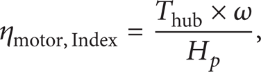
where Thub represents the applied torque to airflow by hub and H p is the brake horsepower. Equation (11) is used to attain the motor efficiency as illustrated in Figure 14(d).
Apparently, the motor efficiency is not deviated significantly such as cases A (84.4%), B80 (86.8%), and B60 (82.3%). However, it is easy to find that the motor efficiency decreases for an increasing loading on motor. Nevertheless, the motor efficiency drops sharply for cases with the inhale-return phenomenon, which happens in cases C50, C70, and D92. Through realizing the loading characteristic of fan motor, fan designers can accordingly choose an appropriate parameter to construct the geometric housing for operating with less energy consumption. Thus, with the comparison of experimental and predicted efficiency, this work successfully decides the corresponding efficiency of the hidden ceiling fan to offer important information for fan user and designer.
5.4. Acoustic Noise Evaluation
The noise frequency spectrum of fan is also measured in the semianechoic chamber to correlate with performance for an overall understanding. The sound pressure levels (SPL) generated are illustrated in Figure 15 for various rotational speeds. Observing the result at median speed as example (Figure 16), it is found that the SPL settings with and without fan guard are 56.2 dBA and 55.2 dBA, respectively. The fan with guard delivers less flow rate and extra1 dBA noise level. Furthermore, the test results: cases B80 (55.2 dBA), B60 (56.3 dBA), B40 (59.9 dBA), and B20 (60.4 dBA) can be used for comparing the acoustic SPL of blockage effect. Obviously, the shorter blockage distance yields the higher dBA. This implies that the blockage effect declines not only the power and performance but also downgrades the noise feature.

SPL comparison of all cases at various speeds.

SPL spectrum comparison for various parameters at medium speed.
For the parameter of housing-ring height, the comparison on cases C30 (55.2 dBA), C50 (57.8 dBA), and C70 (58.7 dBA) shows that the higher housing ring creates a noisy SPL. On the contrary, the larger inlet-to-outlet area ratio not only prevents the inhale-return phenomenon, but also generates a lower acoustic output. Note that when observing the inhale-return phenomenon that appears in cases C50 (57.8 dBA), C70 (58.7 dBA), and D92 (56.4 dBA), it is found that these SPLs are not extremely high as expected.
6. Conclusions
This integrated performance-evaluation scheme consists of aerodynamic performance analysis, efficiency index estimation, motor characteristic prediction, and noise level calculation. The undesirable flow patterns, power consumption, and noise level can be clearly identified in this investigation. Furthermore, the flow visualization results inside the hidden ceiling fan as a design reference to enhance its performance. With the understanding of flow phenomenon for various system resistances, fan designers can accordingly conduct the feasible modifications to improve the fan performance, efficiency, and noise.
The results showed that the setting of guard will change the airflow to a wider distribution with a lower velocity but it does not increase the airflow rate. Also, the inappropriate design of blockage heights will largely reduce the airflow rate, consume the power, and increase the noise. In this study, the blockage height should be set larger than 80 mm for a 356 mm in diameter rotor. This means that the ratio of rotor diameter to blockage height must be kept at a value less than 4.45 to prevent the blockage effect. In addition, both fan guard and blockage heights do not invoke the inhale-return phenomenon at various operating speeds.
Besides, the inappropriate designs of enclosing housing, such as high housing-ring height and low inlet-to-outlet area ratio will induce the inhale-return phenomenon. It is suggested that the height of housing ring should not be bigger than 30 mm, and the inlet area should not be set to a smaller value than the outlet area for avoiding the inhale-return phenomenon. Furthermore, all the parameters have shown the same trend as the ceiling fan is operating under different rotational speeds.
Conflict of Interests
The authors declare that there is no conflict of interests regarding the publication of this paper.
Footnotes
Acknowledgment
The authors would like to thank the financial supports under Ministry of Education (MoE) Top University Projects—102H223401 and 102M21005.