
Abstract
This paper presents design and implementation of an attitude and heading reference system (AHRS) based on low-cost MEMS sensors and complementary filtering (CF). Different from traditional solutions, information fusion is performed with Euler angles directly, which is more straightforward for understanding; however it proposes many challenges for reaching a stable and accurate estimation as when these angles approach or traverse their range boundaries, estimation may get discontinuous. Thus an effective discontinuity avoiding strategy is suggested in this paper to refine the estimation. Besides, instead of extended Kalman filtering (EKF), CF is utilized for state estimation of AHRS as it features fusion of high-frequency and low-frequency signals. In order to make up for shortcomings of MEMS sensors such as multiple errors, drifts, and bad accuracy, some effective calibration and filtering algorithms are proposed to guarantee agreeable AHRS performance. Also, architecture of the MEMS IMU (inertial measurement unit) and mathematical principles for AHRS solution are explained and implemented in this paper. Meanwhile, experimental comparisons have proved feasibility and acceptable performance of this AHRS design.
1. Introduction
The attitude and heading reference system (AHRS) provides roll, pitch, and yaw information of carriers with respect to local geographic coordinate frame, which is essentially required for navigation, guidance, state estimation, and control in applications such as UAVs, spacecrafts, tactical missiles, and other commercial or civil fields [1–4]. Due to restrictions from expensiveness, complexity, weight, and large space consumption, traditional gimbaled inertial navigation system based on mechanical gyroscopic instruments does not always fit best [5, 6]. Meanwhile, with progress of microelectromechanical system (MEMS) technology, AHRS built with low-cost MEMS gyroscopes, accelerometers, and magnetometers [7–10] have attracted attention of engineers and are replacing traditional attitude estimation systems in many applications as they come more economical, compact, and convenient [5, 11, 12].
Hardware configuration of a MEMS AHRS normally consists of inertial and magnetic sensors, or rather MEMS ICs of rate gyros, accelerometers, and magnetometers [13] of all three Cartesian axes, as well as a data acquisition and processing engine to provide solved attitude and heading solutions [14–17]. Rate gyros directly measure rotation rates, and by integrating those rates we can get rotation Euler angles. Meanwhile accelerometers and magnetometers also jointly give Euler angle solutions according to gravity and magnetic measurements. Although MEMS sensors are more compact and cost effective, unfortunately they also have their own drawbacks. Compared with mechanical or fiber-optic gyroscopes, MEMS gyroscopes have a much lower accuracy and are seriously affected by drifts and measurement errors. In a short span of time, attitude can be estimated from integration of rotation rates [18] which tracks the attitude changes closely. Nevertheless, minimal errors from rotation rates will get integrated into an enormous error of the rotation angle as time elapses. MEMS accelerometers together with magnetometers offer accurate attitude and heading estimation of static carriers but are prone to be contaminated by inertial forces, vibrations, or magnetic noises. It is easy to see that frequency characteristics of these two estimations are complementary to each other and would compensate for the other's weakness. Integration from gyroscopes tracks attitude changes closely and quickly, while observation from accelerometers and magnetometers corrects accumulated error of gyroscopes and makes the attitude and heading estimation continuously convergent and accurate.
Typically, an extended Kalman filter (EKF) [6, 8, 18–27] is applied to AHRS for data fusion of multiple sensors and optimal state estimation [4, 17, 22, 28]. However attitude and heading estimation with MEMS AHRS are a problem that can be appropriately addressed by a complementary filter (CF) just right, as the system has two independent measurement accesses for the same estimation. Namely, rotation rate integration of gyroscopes gives good state estimation only in high frequency region, while measurements of MEMS accelerometers and magnetometers only provide good attitude and heading observation in low frequency region. A complementary filter combining merits of both estimations will perform agreeably in whole frequency range. Besides, although quaternions have many advantages over Euler angles for attitude description, Euler angles seem more meaningful and understandable which actually makes them more suitable and straightforward for application. However, thus far, most AHRS solutions have adopted the quaternions, as Euler angles will cause some additional problems for estimation.
Fusing state estimations with Euler angles by an effective antidiscontinuity strategy, this paper presents the design and implementation of an AHRS based on MEMS sensors and complementary filtering (CF). Paper content is organized as follows. Section 2 describes general hardware architecture and sensor configuration of AHRS. Introducing mathematic basis of the system, Section 3 lays theoretical foundation for AHRS. Algorithms adopted for AHRS including complementary filtering and RK4 are interpreted in detail in Section 4. In Section 5 the antidiscontinuity attitude fusing with Euler angles gets realized and explained specifically. For calibrating original raw sensor measurements, Section 6 analyzes error models of MEMS sensors. Then it comes to experimental tests and validation in Section 7. Finally, Section 8 summarizes the system design and some meaningful conclusions.
2. General Hardware Architecture of AHRS
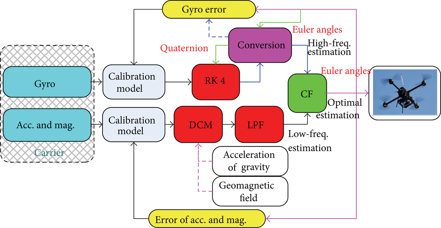
Compared with hardware architecture of an IMU which normally provides original raw data of inertial sensor measurements [14] only, AHRS usually has an additional on-board processing engine for attitude and heading computation [29]. Owing to MEMS technology, researchers are able to build a miniature inertial measurement unit (MIMU). Hardware architecture of AHRS is shown in Figure 1. The InvenSense MPU-6000 motion processing unit with an embedded 3-axis MEMS gyroscope, a 3-axis MEMS accelerometer, and an auxiliary I2C port which connects to third party digital sensors such as magnetometers has been chosen as host sensor. A third party 3-axis MEMS magnetometer, HMC5883L of Honeywell, gets linked into MPU-6000 through that auxiliary I2C port. Thus, the digital motion processor within MPU-6000 gets access to all sensor axes and pipes preprocessed sensor data into an ARM architecture STM32 processor through SPI, which carries most computation payload of attitude and heading solution for AHRS. Optimal attitude and heading estimation output can be delivered through an USART port to a monitoring PC or other application devices, for instance, a quadrotor UAV, and so forth, at up to 100 Hz.

Hardware architecture of AHRS.
3. Mathematical Background of Attitude Estimation
For attitude definition of a rigid body in 3D space, commonly there are three options: Euler angles, quaternions, and the Direction Cosine Matrix (DCM). They identify body attitudes with 3 parameters (ψ, θ, ϕ), 4 parameters (q0, q1, q2, q3), and 9 parameters (C3*3), respectively.
3.1. DCM
Direction Cosine Matrix (DCM) maps vectors in Newtonian reference frame to body fixed frame during fixed-point rotation of a rigid body. When using the Z-X-Y Euler angles, the DCM is given as (1). The relationship between R R and R b is expressed as (2):

With angular rate measurement Ω Rb b which is an angular rate vector given as (4), DCM could be computed according to (3). By the way, sk(Ω Rb b ) stands for the skew matrix of Ω Rb b and is given as (5). This DCM method describes body attitude effectively in full attitude space. Nevertheless, solving (3), there would be 9 subequations with a large computation payload, which poses a great challenge for the embedded processor and slows down the attitude estimation calculation process:

3.2. Euler Angles
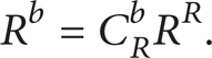
Euler angles are three angles introduced by Leonhard Euler to describe orientation of a rigid body. Mathematically, Euler angles represent three composed sequential rotations that move a reference frame to a given referred frame. According to different rotation sequences, there exist 12 sets of Euler angles. As is shown in Figure 1, this paper takes Z-X-Y set of Euler angles as example, which is considered one of the most appropriate sets for depicting pitch, roll, and yaw of aerial vehicles and is explained with Figure 2. Unless specified otherwise, Euler angles mentioned in the paper are all of this set.
Z-X-Y Euler angles.
According to differential equations of Euler angles given as (6), ψ, θ, and ϕ can be solved based on angular rate measurements. Only three differential equations need solving before the attitude gets clearly estimated. However, there exists a serious shortcoming with this solution. As cos θ approaches zero, the differential equations degrade fast and the solution becomes badly inaccurate, which means that these equations cannot give effective attitude solution at some singular points of the attitude space:

3.3. Quaternions
In mathematics, quaternions refer to an algebraic system extending the complex numbers firstly introduced by Irish mathematician William Rowan Hamilton in 1843. One classic application of quaternions is to replace Euler angles or DCM for attitude description of rigid bodies and computer graphics.
Quaternions are mathematically denoted as (7), where q0, q1, q2, and q3 are all real numbers. Specifically, when used for attitude description the quaternions should have a norm equal to 1. As is known to all, three rotations around different axes defined by Euler angles can be replaced with one rotation around a certain vector in the reference frame. A quaternion is capable of describing that rotation just right:

Suppose there is a rotation of θ around an axis defined by DCM vector (cos α, cos β, cos γ), the corresponding quaternion would be given as (8). A vector R would be expressed as (9) after that rotation with respect to the reference frame:
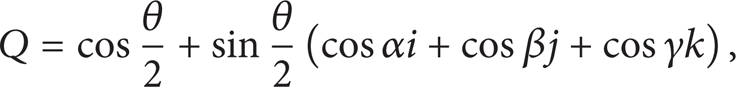


Expanding (9), we can get a more clear view of how the quaternion works compared with the DCM from (10). The quaternion Q can be calculated with differential equation as (11). Compared with Euler angles, the quaternion solution does not have the singular point problems and works effectively within the full attitude space. Meanwhile, it has a lower computation payload and does not have to deal with trigonometric numbers, which guarantees a high processing efficiency:

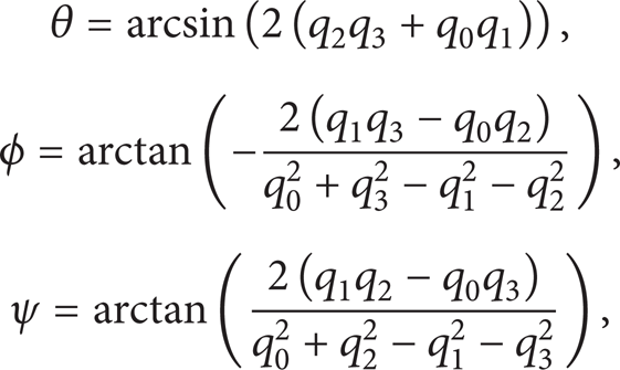
Composing (1), (2), and (10), Euler angles will be easily solved as (12). On the other hand, given the Euler angles, quaternion is calculated as (13):

4. AHRS Based on RK4 and Complementary Filtering (CF)
Software configuration of AHRS solution is shown in Figure 3. Obviously there are two independent measurement accesses for attitude and heading estimation.
Software configuration of AHRS.
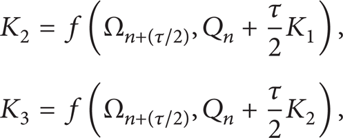
The first access comes from integration of angular rates measured by MEMS gyroscopes, which only performs well in high frequency region but is inevitably affected by gyro drifts. Without an additional observation for drift correction, the attitude based on integration of angular rates would gradually diverge from the real attitude. For solving (11), RK4 (4-order Rungse-Kutta), a numerical solution for differential equations, is adopted for attitude and heading estimation in high frequency region. We simplify (11) into (14) for convenience of explaining RK4. According to RK4, attitude quaternions can be recursively figured out as (15), where K1, K2, K3, and K4 are given by (16) to (18) and τ represents the elapsed time between two sequential quaternions:


The other estimation access is jointly provided by accelerometers and magnetometers. Local gravity G R and geomagnetic field H R are two natural independent reference vectors that would be measured as G b and H b with respect to body coordinate frame. From (2), we get relationships between reference vectors and measurements as

According to (19), Euler angles can be calculated as the following equation:

This estimation does not diverge but is easily affected by vibrations or magnetic interferences, for which a low-pass filter is applied for smoothing that estimation. Finally, the optimal attitude is fused with a CF, which guarantees an agreeable performance in both high and low frequency regions combining merits of those two estimations.
Meanwhile, the software estimates MEMS sensor errors online and compensates sensor measurements according to their calibration models, which are further explained in Section 6.
5. Design of CF and Attitude Estimation with Euler Angles
As is shown in Figure 3, the final attitude is fused and given in Euler angles. In order to describe body attitudes in full space without any ambiguity, possible values of pitch, roll, and yaw angles are restricted within ranges of −90°∼ + 90°, −180°∼ + 180°, and −180°∼ + 180°, respectively.
The CF is structured as Figure 4 and all estimations are given in Euler angles. It calculates difference between the two input estimations as the error signal, which is used to correct Euler angles got from integration of angular rates. Parameter K determines how much of the error would be used for that correction each time. On short time scales, the final output is dominated by integration of angular rates but converges to estimation with accelerometers and magnetometers on long time scales. Adjusting the K parameter, we can conveniently set that time scale. Usually K would be far less than 1.

Internal structure of CF.
According to details of CF principle unveiled with Figure 4, we may find out some flaws with this solution. As is known, continuous attitudes may not be described with continuous Euler angles. Thus, when attitude Euler angles are approaching or traversing their domain boundaries, large differences may occur between its two input estimations, which indicate an ineffective error signal. In these cases, the attitude output will begin to swing and deviate from the real value seriously; namely, the estimated orientations are not continuous.
In order to give continuous, accurate, and stable attitude and heading estimations, we designed a discontinuity avoiding strategy. Technically and specifically speaking, there are three cases.
(a) Case. When the yaw angle changes from a value close to + 180° to a value close to − 180°, a large error may occur between yaw angles of the two estimations and vice versa. As shown in Figure 5 with red arcs, normal differences between the two input yaw angle estimations should be within an acceptable range. However, once that range covers the domain boundary (+/−180°), adjacent attitudes may be differed by an abnormal mathematical difference which exceeds the normal range a lot and may disturb the CF estimation.
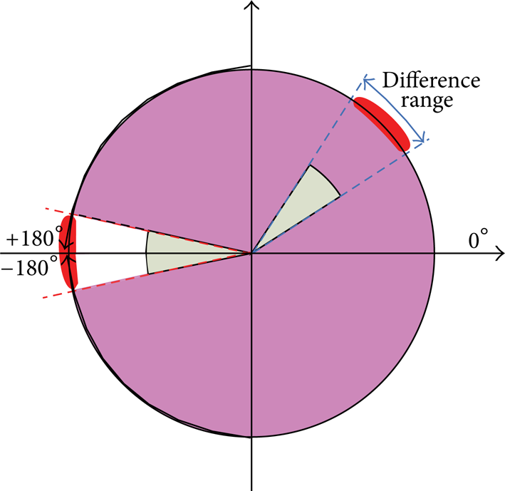
Case of yaw/roll angle.
Solution. Compare the calculated input difference with the normal difference range and adjust the final output yaw angle estimation according to the algorithm described in pseudocode language as in Algorithm 1.

Figure 6 gives a comparison between outputs with and without antidiscontinuity process of the yaw angle in this case.

Output comparison of yaw angles.
(b) Case. As is shown in Figure 5, similar to the yaw angle, when the roll angle changes from a value close to + 180° to a value close to −180°, large error may occur between roll angles of the two estimations and vice versa.
Solution. Compare the calculated input difference with the normal difference range and adjust the final output roll angle estimation accordingly. The algorithm is described in pseudocode language as in Algorithm 2.
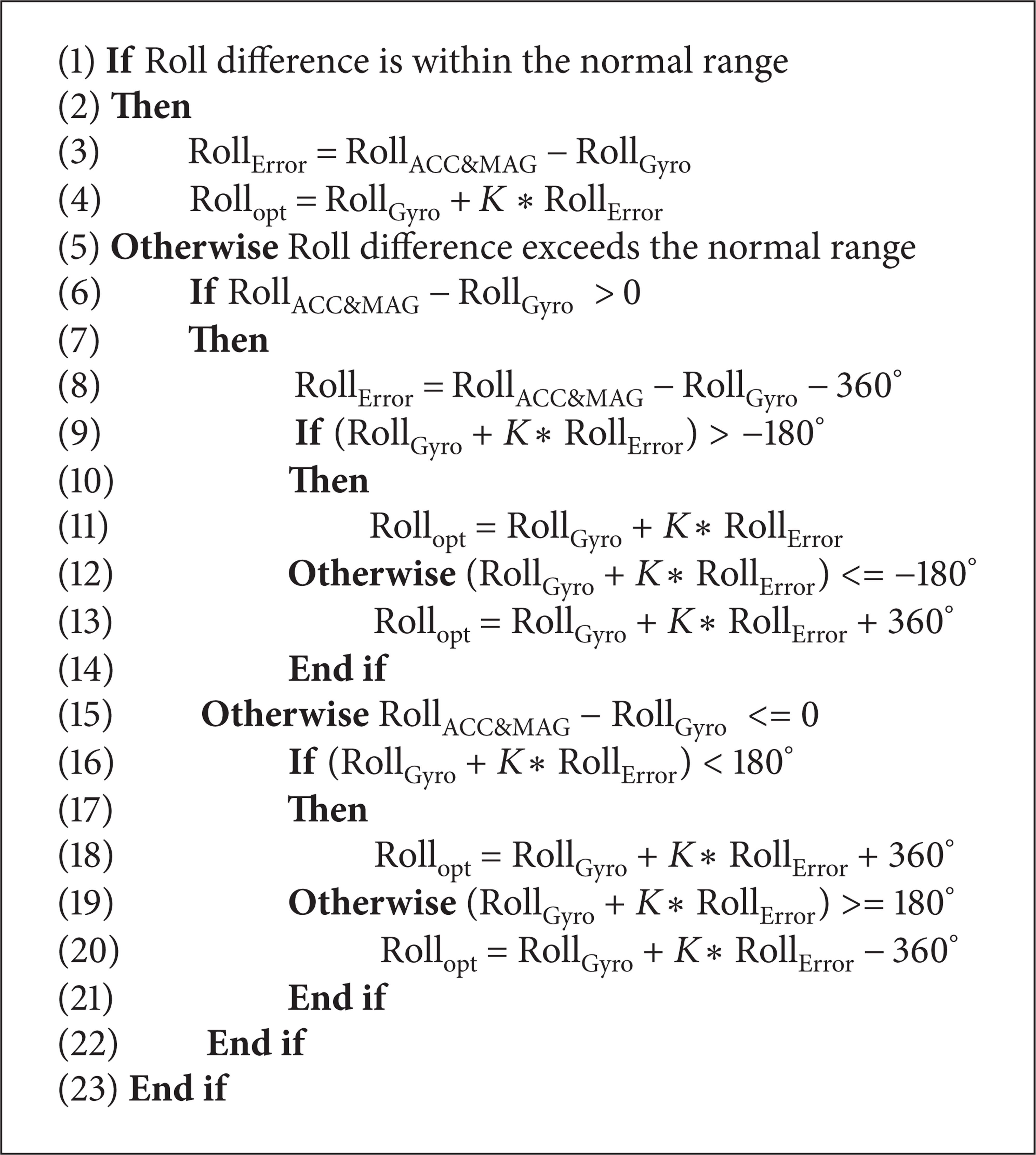
Figure 7 gives a comparison between outputs with and without antidiscontinuity process of the roll angle in this case.
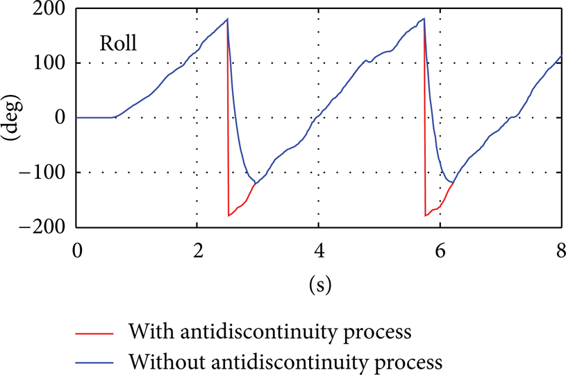
Output comparison of roll angles.
(c) Case. When the pitch angle wanders around + 90° or −90°, estimation fusion with Euler angles would meet the biggest challenge. According to Figure 8, every time the pitch angle traverses + 90°or −90°, although there will not be a sudden change to the pitch angle, both roll and yaw angles should be increased or decreased by 180° coordinately (subject to their value ranges). Problems including large roll or yaw angle errors and uncoordinated changes of roll and yaw angles may arise at the same time.

Case of pitch angle.
Solution. Force the other to change if one of the roll and yaw angles changes greatly when the pitch angle is close to + 90° or − 90°. Then take the adjusted estimation result as output directly. Relevant algorithm can be found in Algorithm 3.

Figure 9 gives a comparison between outputs with and without antidiscontinuity process of the roll angle and the yaw angle in this case.

Output comparison of yaw angles.
6. Calibration Models of MEMS Sensors
Original sensor measurements are inevitably affected by installation misalignments between sensor axes and axes of the reference body coordinate frame [30, 31]. Besides, low-cost MEMS sensors are usually distorted by both colored and Gaussian white noises as well as the initial bias errors, inconsistent sensitivities, and nonorthogonal errors of sensor axes [32, 33]. In order to get the measurements more accurate and smooth, calibration models for sensor measurements are built as follows, which have been proved adequate for a moderate AHRS [22, 34].
6.1. MEMS Gyroscopes
Experimental tests have shown that gyroscope measurement errors majorly come from the following items: initial bias and drifts over temperature. They can be formulated as (21). And the calibrated gyroscope measurements are given as (22):
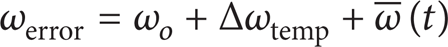

where ω
o
represents the initial bias error of the gyro, Δωtemp indicates measurement drifts over temperature, and
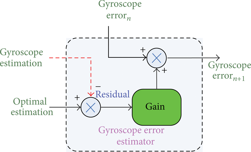
Gyroscope error estimator.
6.2. MEMS Magnetometers and Accelerometers
Manufacturing errors from MEMS sensors themselves together with installation misalignments have made calibration models for magnetometers quite complex. Usually full calibration is considered as (23). The upper triangular matrix compensates for nonorthogonal errors and the symmetry matrix corrects installation alignment errors:

Calibration of accelerometers has a similar model except that the nonorthogonal error is ignored. It can be given as
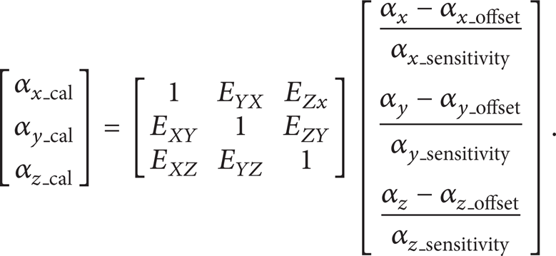
Meanwhile, (23) and (24) are subject to constraints from (25) and (26):
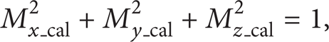

As the magnitude does not make any sense for attitude estimation, it is taken as one unit in (25). According to (23) to (26), with abundant measurement data at different attitudes, we can compute calibration parameters in (23) and (24) using the method of least squares. Without calibration, raw measurement data map an ellipsoid as shown in Figure 11. The calibrated sensor data are distributed on the surface of a normal sphere centered at the origin. Figure 12 shows data distribution after calibration.

Raw measurement data (mag. and acc.).
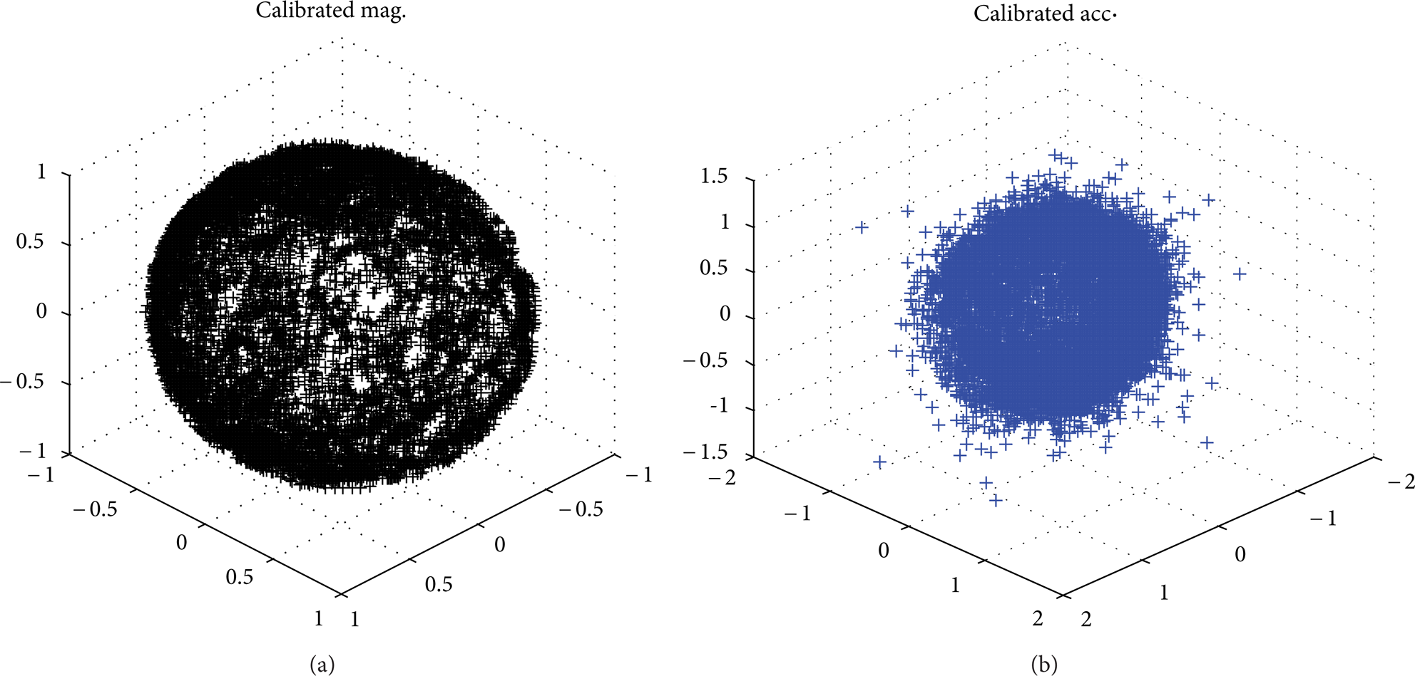
Calibrated measurement data (mag. and acc.).
7. Experiment Result Visualization and Validation
In order to make the AHRS output visible, we coded a monitoring program based on Windows MFC and OpenGL that rends a virtual rigid body according to the output attitude and draws curves of Euler angles, gyro rates, and accelerometer and magnetometer measurements simultaneously. Figure 13 introduces architecture of the AHRS monitoring system.

Architecture of the AHRS monitoring system.
Further validating the AHRS performance, output comparisons between this low-cost MEMS AHRS and the MTi AHRS, a commercial AHRS product using EKF, are given. As is shown with Figure 14, we fixed both AHRS on the same carrier. Results in Figure 15 prove feasibility, stableness, and accuracy of the low-cost MEMS AHRS based on CF designed in this paper.
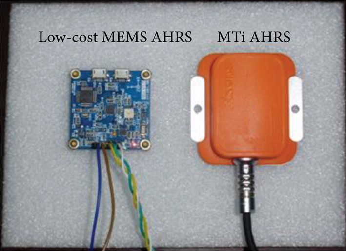
Experiment setup.
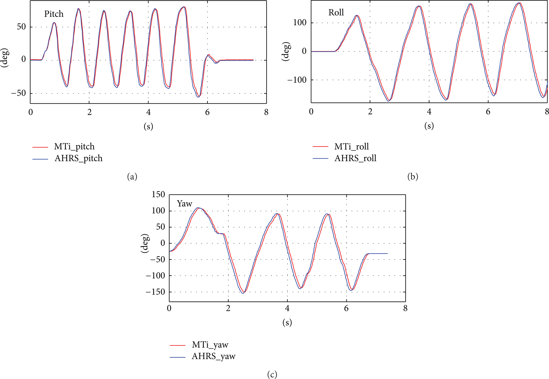
Output comparisons of pitch and roll.
8. Conclusion
As is explained in the above sections, we have designed and implemented an AHRS with low-cost MEMS sensors. Instead of EKF, CF has been adopted to estimate the optimal attitude and heading information with Euler angles. Although attitude fusion in the form of Euler angles would cause output swing at some singular points without postprocess for discontinuity avoidance, Euler angles bring more convenience to the applications and describe attitudes more straightforwardly. However, it has been proved possible with a delicately designed antidiscontinuity strategy. Low-cost MEMS sensors, especially MEMS magnetometers, have great measurement errors. Practically effective sensor calibration models are usually required for accurate attitude estimation. Experiments and comparisons with the Xsens MTi AHRS product demonstrate agreeable performance of this design.
Conflict of Interests
The authors declare that there is no conflict of interests regarding the publication of this paper.
Footnotes
Acknowledgments
This work was supported by the National High Technology Research and Development Program of China (“863” Program) (2012AA041402) and National Natural Science Foundation of China (Grant no. 61175079 and no. 51105012).