
Abstract
This paper presents a rational prediction of temperature field on the differential hybrid system (DHS) based on the thermal network method (TNM). The whole thermal network model is built by considering both the contact thermal resistance between gasket and planet gear and the temperature effect on the physical property parameters of lubricant. The contact thermal resistance is obtained by using the concept of contact branch thermal resistance and G-W elastic model. By building an elaborate thermal network model and computing models for power losses and thermal resistances between components, the whole temperature field of DHS under typical operating condition is predicted. Results show that thermal network method can be effectively used to predict the temperature distribution and the rule of temperature variation, the surface roughness significantly affects contact thermal conduction, and the decrease in the thermal resistance of the natural convection between air and DHS housing can effectively improve the thermal environment of DHS.
1. Introduction
Thermal management has become a significant approach to improve fuel economy and dynamic performance of a vehicle [1, 2]. With the issues of environmental pollution and energy crisis, hybrid electric vehicles (HEVs) have attracted considerable attention [3, 4]. As the key component in HEV, power split device (DHS) affects vehicle performance and control strategies. Among various alternative powertrains, the planetary gear hybrid powertrain is considered as one of the most promising configurations for HEVs [5]. However, the planetary train was circumscribed by its structure, such as small inner space, multiple gear meshing, and higher power losses, which caused the frequent occurrence of the scuffing failure of gears and thermal burning of the gasket. This condition restricts the operating range of DHS and the control strategies of multipower sources. Thus, a thermal analysis of DHS should be conducted to prevent thermal failure and to provide a method of guidance for the thermal design of DHS. Thus, this work focuses on the temperature field distribution and changing rule of DHS.
Numerous validated and widely used approaches are employed in heat transfer research. These approaches include finite element method, boundary element method, finite volume method, and thermal network method (TNM). TNM has been widely used in engineering fields for its advantages of flexible nodes selection and less calculation time. Reference [6] predicted the power losses of gear transmission by using TNM in the gearbox. References [7, 8] conducted computational fluid dynamics (CFD) thermal modeling and experimental testing to validate the temperatures predicted by the lumped parameter method (LPM) thermal circuit. Reference [9] built the steady and transient temperature fields of a motor through LPM thermal modeling and verified the rationality of TNM through an experiment. Reference [10] conducted the thermal network modeling of a gearbox test device and discussed the immersion depth effect of the gear and pinion on the temperature distribution.
According to the above research results, this paper uses TNM and presents a thermal analysis process based on the differential hybrid system (DHS), which is a new type of DHS proposed by Yu et al. with verified application feasibility [11, 12]. The thermal analysis model of DHS is established based on TNM. To improve the accuracy and rationality of TNM, the heat transfer environment of planet gear and gasket (vulnerability of heat transfer) is first analyzed, and the partial thermal network is rationally built. In addition, based on the G-W elastic contact model, the calculation model of contact thermal resistance between planet gear and gasket is established. And the steady-state heat balance equation is established by building the calculation model of power loss and thermal resistance.
2. Layout of HEV Transmission with DHS
DHS is a new type of PSD based on the traditionally symmetrical planetary gear differential. Through the coupling of the power of engine, motor, and generator, the optimal power coupling strategies between engine and motor can be achieved which can endow HEVs with excellent dynamic performance and the goal of energy conservation and emission reduction is achieved. DHS with two input shafts and an output shaft is located in a closed housing. Layout of HEV transmission with DHS is shown in Figure 1. The rotational movements of two input shafts are synthesized and transmitted to the output shaft.
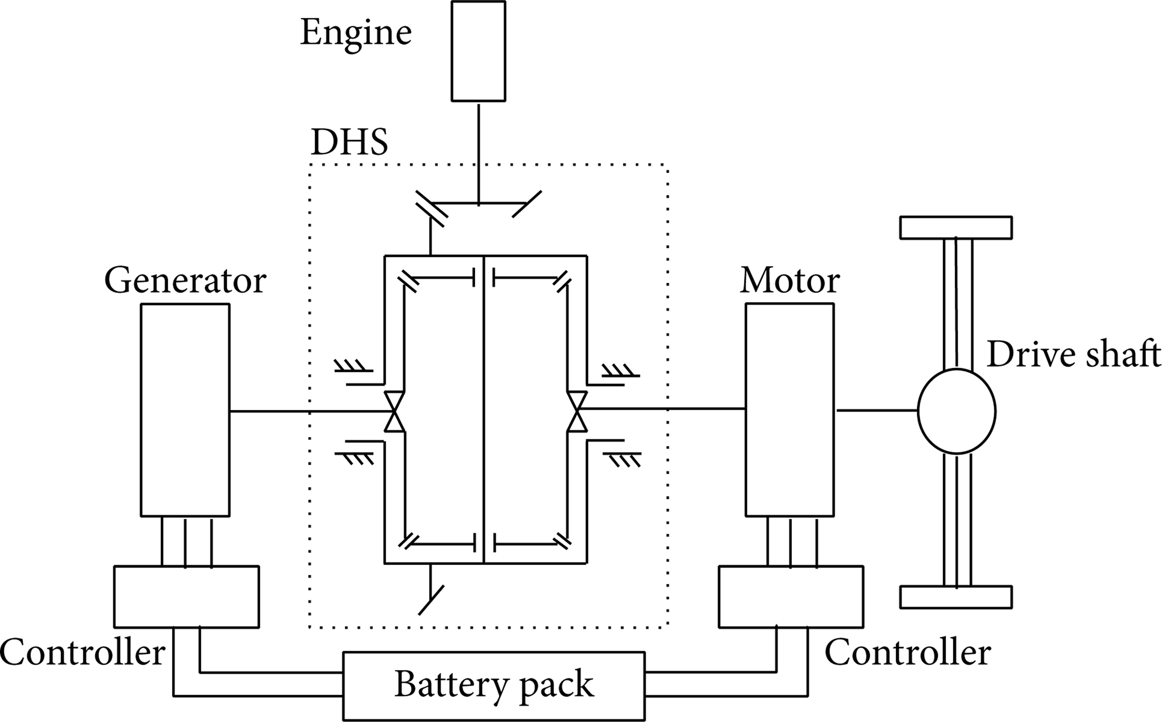
Layout of HEV transmission with DHS.
3. Thermal Network Model of Planet Gear-Gasket System
DHS works under high-speed operating conditions in HEVs. Thus, the speed difference of the generator shaft and motor shaft becomes larger, and the planetary gear rotation speed becomes higher. In this case, these factors result in higher friction power loss between the gear cone back and gasket. Figure 2 shows that the planet gear has two gear meshing points. The gear meshing power loss is converted to heat and dissipates to the surrounding parts. Meanwhile, the needle bearing between the planet gear and planet gear axle also generates a large amount of heat. Thus, accurate thermal analysis should be conducted, and the possibility of failure in the heat weak spot should be investigated when planet gear and gasket produce much heat and cooling capacity is insufficient.

Thermal environment of planet gear-gasket system.
The thermal behavior of a machine or construction is a complex combination of heat generation and heat transfer. Heat is generated in heat sources, such as bearings, seals, and gears, and is transported from and through these heat sources by heat conduction, heat convection, and radiation.
According to the principle of thermoelectric similarity,

The value of thermal resistance depends on the kind of heat transfer, which includes conduction, free or forced convection, and radiation. According to the above thermal environment of the planet gear and gasket, the thermal network model is built as shown in Figure 3. It can be seen that it is necessary to build correct calculating model of contact thermal resistance.

Thermal network of planet gear-gasket system.
4. Contact Thermal Resistance
Two bodies are completely in contact with each other in the friction process of planet gear and gasket nominally, such that thermal flux and temperature on either side of the contact surface are equal [13]. However, from a microcosmic aspect, the two contact surfaces are merely in contact with each other in some asperities because the rubbing surface is uneven. In addition, some gaps filled with the medium or vacuo exist in the small asperities and valleys. Figure 4 shows that only a small number of asperities produce heat through friction. Thus, a few asperities bear a higher temperature, which makes thermoelasticity unstable and can accelerate the thermal degradation of the friction materials and the wear of gasket, eventually causing fatigue failure.

Contact surface from microcosmic aspect.
Contact thermal resistance mainly depends on the following parameters: geometrical morphology and size dimension of the contact asperities, roughness, temperature and compression state of the contact surface, and the thermophysical properties of materials and mechanical property in such state. However, once the contact material is confirmed, the study on contact thermal resistance mainly includes two basic problems: morphology description and deformation assumption. Morphology description studies mainly conduct the statistical analysis of the roughness parameter of the contact surface and obtain the universal law that affects the profile parameters of the contact thermal resistance. The deformation assumption examines the deformation condition of the touch point, thereby applying the relevant parameters to different deformation models.
4.1. Contact Branch Thermal Resistance
Thermal contact resistance is the key problem in solving multilayer solid heat conduction in scientific research and engineering practice. Most related articles that use TNM to conduct thermal analysis only consider the thermal contact resistance at gear meshing point. However, DHS differs from other kinds of gear transmission systems in that the friction between the planet gear and gasket cannot be ignored. Thus, to establish accurate heat balance equations of the overall system and improve the accuracy of thermal analysis, the thermal contact resistance between gasket and gear back cone should be considered.
Contact bodies are usually simplified to the shape of a cuboid, cylinder, or circular truncated cone. As shown in Figure 5, the contact surface is simplified to an orthogon in the two-dimensional case. The contact surface is divided into the contact and noncontact segments, but friction heat only exists in the contact segment [14].

Equivalent model of contact thermal resistance.
As shown in Figure 5, the steady-state heat balance equations of the contact segment of two rough surfaces can be described by

If we ignore the thermal conduction of heat fluxes through the medium between the rough surface and the thermal radiation between gaps, partial thermal resistance can be obtained by

where R A and R C are the conduction thermal resistance of two contact bodies. R B and R D are the synthetic thermal resistance of the i contact asperities. R Bi and R Di are the thermal resistance of the i contact asperities of the rough surface. R Bi can be defined as

where K s is the thermal conductivity of the contact asperities, L s is the equivalent length of the contact asperities, and A ri is the contact area of the ith contact asperities. The contact area of the contact asperities and the number of contact asperities can be solved by establishing the contact model.
Owing to the contact branch thermal resistance concept, the complex relationship between objects of different material can be simplified. Thus, the contact model of the gasket rough surface is built using the concept of contact branch thermal resistance.
4.2. G-W Elastic Contact Model
The friction phenomenon of a rough surface is affected not only by rough topography but also by heat generation and transfer. Thus, to study the distribution of the gasket temperature field, the influence of gasket surface roughness on temperature should be considered. In this study, based on the statistical characteristics describing the surface roughness, the heat transfer rule affected by contact morphology can be investigated.
Greenwood and Williamson proposed the contact model based on statistical analysis called the G-W elastic contact model [15]. To confirm the geometrical parameters of the contact model, five basic assumptions are adopted: (1) the rough surface is random; (2) the top of asperities is a sphere; (3) all curvatures of the asperities are uniform, which highly obey Gaussian distribution; (4) the distance between the asperities is large enough, and no interactions occur between them; and (5) the asperities have no large deformation.
The asperities height distribution of a rough surface conforms to standard normal distribution. The root-mean-square values of roughness are σ1 and σ2, respectively, and the probability density function can be defined as

where
The practical contact area A r can be calculated by the following equation:
The relation of the pressure load and d can be confirmed by the following equation:
The number of asperities n which participated in contact can be calculated by the following equation:
The number of asperities n and practical contact area A r can be obtained by analyzing the rough surface. The model of the gasket contact thermal resistance is established through the above methods and applies to the whole thermal network model of DHS. Thus, the heat transfer model of the whole thermal balance equation can be built, and the situation of DHS temperature field distribution and gasket can be analyzed. The process of DHS thermal network model established using TNM will be expounded in the next section.
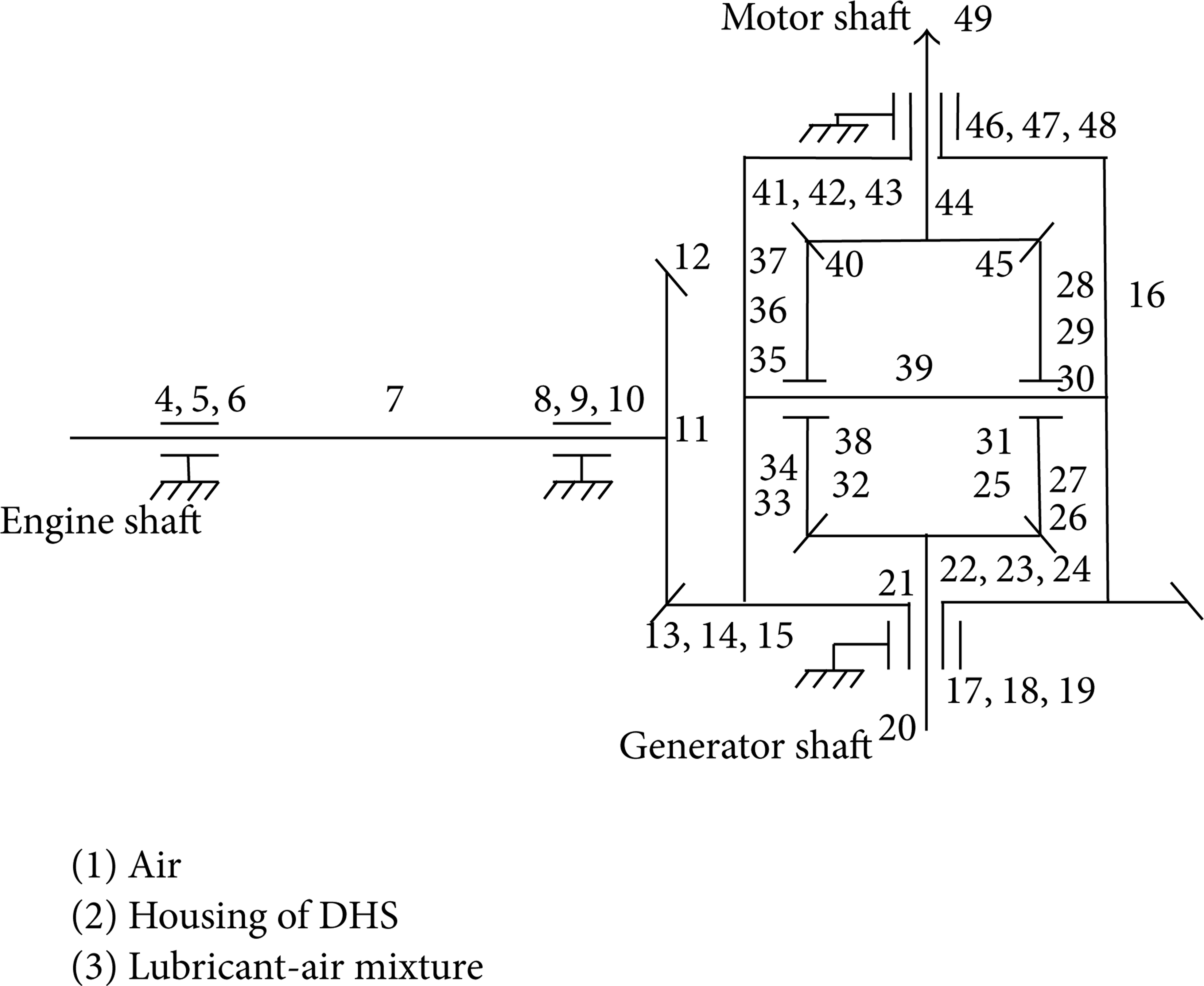
5. Establishment of DHS Thermal Network Model
Based on the principle of LPM, DHS is divided into 49 temperature nodes. Each temperature node represents an isothermal body or surface. The heat weak spot of the planet gear and gasket is divided more intensively, and the other parts of the node temperature are divided relatively sparsely [16]. The distribution of the temperature nodes is shown in Figure 6. The locations of each node of the thermal network are listed in Table 1. The whole thermal network model of DHS is established as shown in Figure 7.
Location of each node of thermal network.

Distribution of the temperature nodes.

Thermal network model of DHS.
5.1. Power Loss
Power losses serve as a significant function in predicting a temperature field with TNM. Once a thermal network is built, power losses have to be estimated, and the generated heat should be imposed at the relevant nodes. Power losses in geared transmissions are traditionally decomposed into no-load and load-dependent contributions. The latter comprises friction at the mating teeth and in the rolling element bearings, whereas no-load losses mainly stem from oil churning and oil shearing in journal bearings. Windage losses are neglected because rotational speeds are limited. For each individual dissipation source, the following formulas have been implemented in the simulation code.
Tooth Friction Losses. The power losses of gear meshing [17] can be evaluated as

where H v represents the gear geometry and f is the friction coefficient.
Rolling Bearing Losses. The rolling bearing losses [18] Pbear can be estimated by the following equation:

where C f is the friction torque due to the applied force and C v is the viscous friction torque; both are estimated using Harris’ formulas.
Frictional Power Losses. The friction power loss between planet gear and gasket cannot be ignored in DHS. Friction power losses can be calculated by the following equation:

where μ is the frictional coefficient of contact surface, F N is the normal pressure, ω is angular velocity of gear, and R is gear radius.
Oil Churning. Churning losses have been estimated by using the empirical formulas of Changenet et al. [6], which lead to the following expression of the churning power loss Pchurn:

where S m represents the submerged surface area of the gear and C m is dimensionless torque that depends on the fluid flow around the rotating gears.
5.2. Thermal Resistance
Thermal resistance is a key parameter in thermal analysis and includes conduction, convection, and radiation according to the method of heat transfer. The effects of radiation can be ignored because of the small temperature difference among components [19]. The modeling details associated with the definition of thermal resistance of conduction and striction can be found in de Gevigney et al.'s study [10], and only the specific resistances of convection are presented in the following sections.
The thermal resistance of convection is expressed in terms of the exchange surface area (A) and the heat-transfer coefficient for convection (hconv), which depends on the Nusselt number (Nu), fluid thermal conductivity (k), and characteristic length (L) as follows:

According to the heat transmission paths of the parts in DHS, heat convection can be classified into the following kinds:
heat convection between the outer face of the DHS housing and air and that between the inner face of the DHS housing and gas-oil mixture;
heat convection between surfaces of the differential mechanism housing and gas-oil mixture;
heat convection between the surfaces of gear and gas-oil mixture;
heat convection between gas-oil mixture and shaft and bearings.
The convective heat transfer coefficients of gears, shafts, bearings, and other standard components can be found in [12]. In this paper, only the heat transfer coefficients between housing and lubricants and that between housing and air are calculated and analyzed.
The outer face of DHS housing is simplified to a spherical surface, and natural convective heat transfer occurs between air and the outer face of the DHS housing. The geometric construction of inner face of DHS housing is intricate, and the lubricant in DHS is under a complicated state of motion. Thus, to simplify the calculation the inner face can be considered as an assembly of flat plates. The following relations have been used to quantify the heat-transfer coefficient of convection.
The empirical formula of natural convection for outside surface of sphere is described by

For convection between flat plate and lubricant,
In these equations, Nusselt (Nu), Reynolds (Re), and Grashof numbers (Gr) are defined by using the plate length (or height for vertical ones) as the characteristic dimension resulting in an average value of Nu along the plate.
Meanwhile, to improve the precision of the temperature field obtained by using TNM, the variations of ρ, c p , and k under different temperatures are considered:

First, temperature of lubricant is determined based on original parameters, and the temperature is iterated to the temperature function to obtain a new and more precise temperature. Thus, a set of more precise parameters is obtained, and the convective heat transfer coefficient is used in the thermal network model.
6. Results and Discussions
The generator shaft can be controlled by DHS to enable the engine to work under the optimum speed spectrum. When DHS is working under combined driving mode, the input power is high, such that a set of typical working conditions under combined driving mode is selected to predict the DHS temperature field. The parameters of the typical working conditions and properties of lubricant are listed in Tables 2 and 3.
Typical driving conditions of HEV.
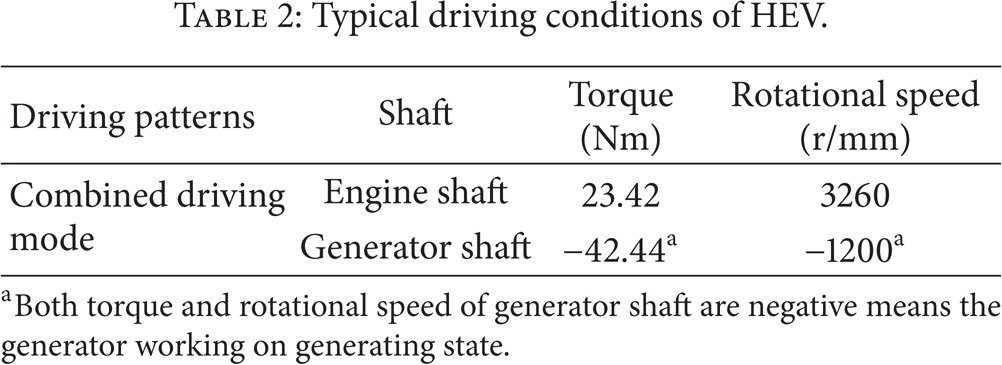
aBoth torque and rotational speed of generator shaft are negative means the generator working on generating state.
Properties of lubricant.

The temperatures of crucial components under typical operating conditions were calculated by TNM, as shown in Table 4. In addition, owing to the complex heat transfer conditions of the internal system of planet gear-gasket in DHS, the temperature of the differential housing, needle bearing, and lubricant, the contact thermal resistance of planet gear-gasket, and friction power loss were set as the boundary conditions; the heat conduction model of planet gear-gasket was established by ABAQUS, and then the temperature field distribution of contact surface of planet gear-gasket was obtained as shown in Figures 8 and 9. In a local system of planet gear-gasket, the average contact temperature is the highest at 166.87°C. By contrast, the average temperature obtained by thermal analysis is approximately 145°C. The error is approximately 13.1%, which is obtained from the simplification of the geometry and calculation models in TNM.
Temperature distribution of key component.


Gasket temperature distribution.

End face temperature distribution of planet gear.
The temperature between the gasket and contact surface is in Table 3. The contact between gasket and planet gear is incomplete, and the surface roughness of gasket significantly affects heat transmission. Figures 10 and 11 show that the surface roughness of gasket affects the contact thermal resistance and the contact surface heat transfer. With creasing surface roughness, the contact thermal resistance and temperature difference between the gasket and planet gear increase gradually. Thus, reducing the surface roughness of soft materials can effectively improve the contact heat conduction.
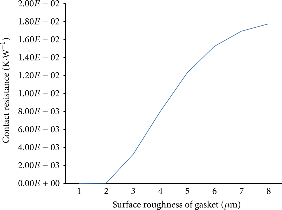
Influence of surface roughness on contact resistance.

Influence of surface roughness on contact heat transfer.
Moreover, the thermal plight inside DHS can be mitigated by adjusting the natural thermal resistance between DHS housing and air. Thus, the possibility of failures can be reduced. The variations of natural thermal resistance between DHS housing and air relative to the temperature of the gasket in DHS are shown in Figure 12. It can be seen that for every decrease of 0.005 K·W−1 in natural thermal resistance, the temperature in the system can decrease by 15°C. The temperature difference between DHS housing and gasket is maintained at approximately 60°C. Based on the data, this condition is unlikely to improve the thermal environment by merely adjusting the geometric parameters of the parts of the system. Meanwhile, by reducing the natural thermal resistance between DHS housing and air, the thermal environment can be profoundly improved. The most effective way to reduce natural thermal resistance is to increase the area of the heat delivery surface. During the design period, some radiating ribs can be added to the DHS housing to increase the heat delivery surface area and reduce natural thermal resistance.
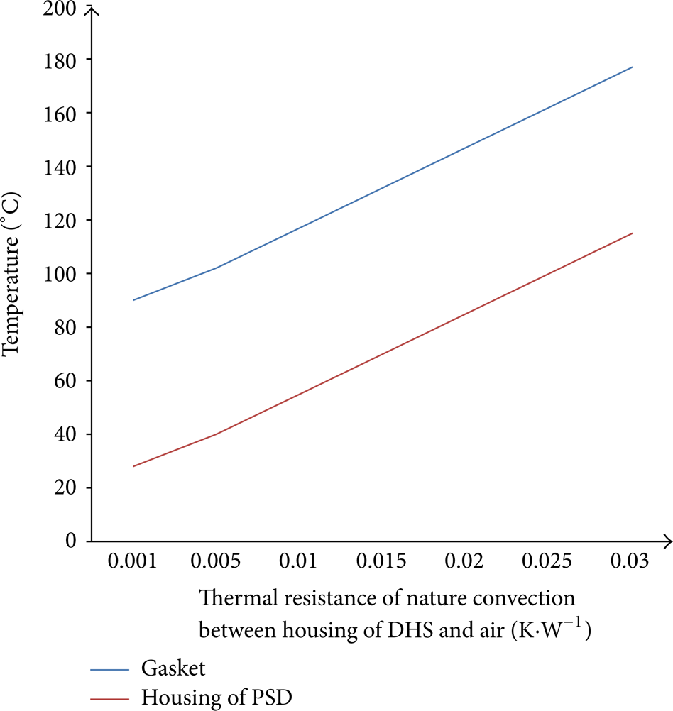
Influence of thermal resistance of natural convection on heat transfer.
7. Conclusions
The whole temperature field of DHS under typical operating conditions is predicted by building the whole thermal network model considering both the contact thermal resistance between gasket and planet gear and the temperature effect on physical property parameters of lubricant; results show that thermal network method can be effectively used to predict the temperature distribution and the rule of temperature variation.
Through the analysis of the result, the roughness of contact surfaces was found to significantly affect the heat transfer between contact surfaces. By reducing the roughness of the contact surfaces, thermal resistance and temperature difference can be reduced. Thus, the efficiency of heat transfer is increased. By reducing the natural thermal resistance between the housing in a DHS system and air, the thermal environment can be improved significantly. For every decrease of 0.005 K·W−1 in natural convection resistance, the temperature in the system can decrease by 15°C. The temperature difference between DHS housing and gasket is maintained at approximately 60°C.
In TNM, the temperature node can be selected flexibly, and calculation is simple and convenient. Thus, TNM is applied to many areas in engineering fields. However, the solution to convective heat transfer coefficients is based on experimental relationships, and the fluid flow state inside a transmission device is hardly predictable. Therefore, the precision of TNM is constrained. To improve the precision of TNM, CFD simulation can be applied to calculate heat transfer coefficients.
Conflict of Interests
The authors declare that there is no conflict of interests regarding the publication of this paper.
Footnotes
Acknowledgment
The authors of the present paper gratefully acknowledge the National Natural Science Foundation of China (NSFC, no. 51075179) for supporting this research.