
Abstract
A six-cable driven parallel manipulator and an A-B rotator in the feed support system of the Five-hundred-meter Aperture Spherical radio Telescope (FAST) are adopted for realizing the position and pose of nine feeds. The six-cable driven parallel manipulator is a flexible mechanism, which may not be stably controlled due to a small cable tension. The A-B rotator is a rigid mechanism, and its stability and accuracy can be improved by small pose angle. Based on the different characteristics, a pose planning function is presented. The optimization target of the pose planning function is to get the smallest pose angle of the A-B rotator, and the constraint condition can reflect the controllability of the six-cable driven parallel manipulator. Then, the pose planning realization process of the feed support system is proposed. Based on the pose planning method, optimized pose angles of the feed support system for the nine feeds are obtained, which suggests that the pose angle of the six-cable driven parallel manipulator changes from 0° to 14° and the pose angle of the A-B rotator changes from 0° to 26.4°.
1. Introduction
China is now building the largest single dish radio telescope in the world in Guizhou province, which is called Five-hundred-meter Aperture Spherical radio Telescope (FAST) [1–3].
Figure 1(a) shows the conceptual design of the FAST. The feed support system of FAST includes two parts: one is a six-cable driven parallel manipulator with a large span that drives the feed adjustable mechanism equipped with a coarse positioning; the other one is a feed adjustable mechanism.
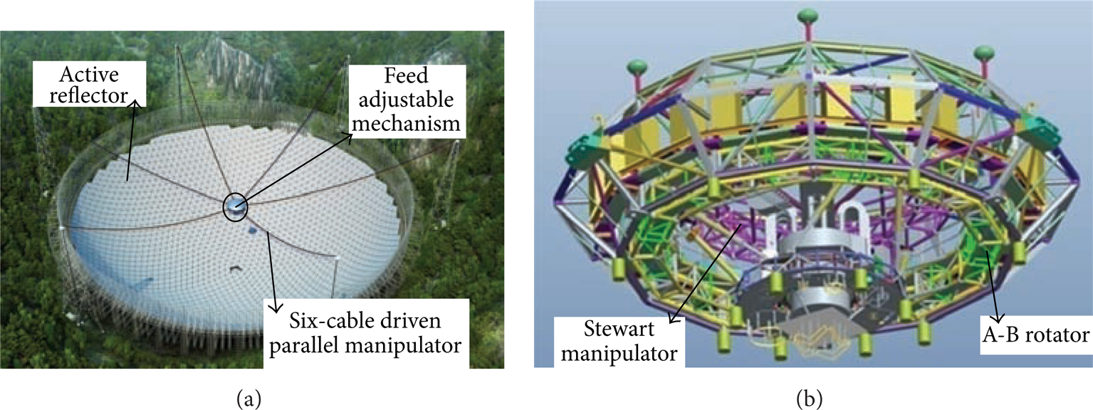
FAST. (a) Conceptual design of the FAST. (b) Focus cabin.
Figure 1(b) shows the feed adjustable mechanism. The feed adjustable mechanism looks like a cabin, and it moves on a focus surface. So it is also called the focus cabin. The diameter of the focus cabin is about 13 m. There are two main mechanisms in the focus cabin: an A-B rotator and a Stewart manipulator.
As shown in Figure 2, nine feeds are fitted on moving platform of the Stewart manipulator. The feeds move on a focus surface to track the celestial sources, and the theoretical position and pose of the nine feeds are controlled by a six-cable driven parallel manipulator and an A-B rotator. A Stewart manipulator, fixed on the A-B rotator, is used to improve the position and pose accuracy of the nine feeds in real time.

Nine feeds on moving platform of the Stewart manipulator.
Poses of the nine feeds are redundantly controlled by both the six-cable driven parallel manipulator and A-B rotator. Six-cable driven parallel manipulator is a flexible mechanism, while A-B rotator is a rigid mechanism. Previous researchers did plenty of work on optimization study of cable driven parallel manipulators and rigid mechanisms, respectively [4–8]. However, for the feed support system of FAST, pose planning method should be studied based on the different characteristics of the six-cable driven parallel manipulator and A-B rotator at the same time. This paper is expected to fill that gap.
Cable can only bear tension but not pressure, so a cable driven parallel manipulator may not be perfectly controlled due to a small cable tension [9–11]. Therefore, cable tension should be taken into account for pose planning of the six-cable driven parallel manipulator. For the A-B rotator, small pose angle can reduce the gravity center change of the feed support system, which improves stability and accuracy of the feed support system.
Considering the important characteristics of the six-cable driven parallel manipulator and the A-B rotator, we explore a pose planning method for the feed support system of FAST. A pose planning function is presented, and the realization process is studied for the feed support system of FAST. The optimization target of the pose planning function is to get a smallest pose angle of the A-B rotator, and the constraint condition can evaluate cable tension, which reflects the uniformity of cable tension and controllability of the six-cable driven parallel manipulator.
In this paper, description and modeling of the feed support system are expressed in Section 2. Static equilibrium equation of the six-cable driven parallel manipulator is also presented for calculating cable tensions. Section 3 proposes the pose planning function and realization process of the feed support system. In Section 4, posing planning results by using the pose planning method in this paper are obtained. Finally, taking Feed 1 as an example, pose angles of the six-cable driven parallel manipulator and A-B rotator are figured out.
2. Description and Modeling of the Feed Support System
2.1. Description of the Feed Support System
As shown in Figure 3(a), the maximum tracking angle of the feeds is 40°, and the tracking angle is realized by the pose angle of the six-cable driven parallel manipulator and the A-B rotator. The focus surface is a spherical crown from about 140 m to 176 m above the active reflector. Six-cable driven parallel manipulator drives the focus cabin to make sure the nine feeds move on the focus surface.
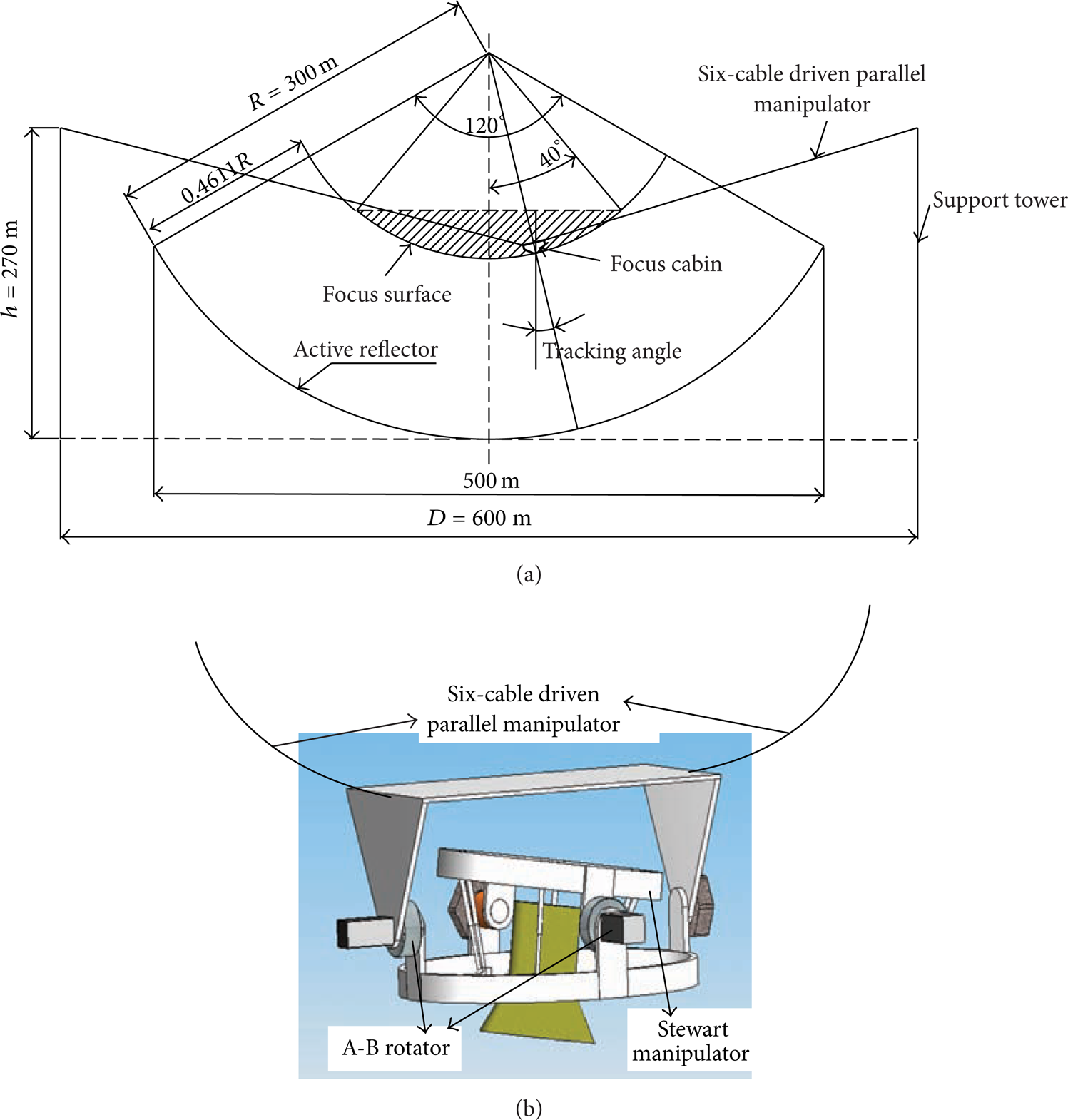
Description of the feed support system. (a) Work surface and tracking angle of the nine feeds. (b) Sketch of the six-cable driven parallel manipulator and focus cabin.
Figure 3(b) is a sketch to show the relationship of the six-cable driven parallel manipulator, A-B rotator, and Stewart manipulator.
2.2. Modeling of the Feed Support System
As shown in Figure 4, related coordinates are defined as follows.

Related coordinates of the feed support system.
The origin point of an inertial frame ℜ:O − XYZ is located at the center of the active reflector's bottom. X-axis points to east direction, and Y-axis points to north direction.
Three cable-cabin anchoring points shape the moving plane of the six-cable driven parallel manipulator. The origin point of moving frame ℜ C :O C − X C Y C Z C is located at the center of the moving plane. Initially, the moving plane of the six-cable driven parallel manipulator is placed horizontally. In this condition, X-axis points to east direction and Y-axis points to north direction.
The origin point of moving frame ℜ AB :O AB − X AB Y AB Z AB is located at the center of A-B rotator. Initially, the A-B rotator is placed horizontally. In this condition-axis points to east direction and Y-axis points to north direction.
The origin point of moving frame ℜ S :O S − X S Y S Z S is located at the center of moving platform of the Stewart manipulator. Initially, the Stewart manipulator is placed horizontally. In this condition, X-axis points to east direction and Y-axis points to north direction.
All coordinates comply with the right-hand theorem.
For analyses, some symbols are used in the following equations. So, related vectors are listed in Table 1.
Vectors of the feed support system.

When a feed is located at a theoretical position for receiving radio waves, the Stewart manipulator remains the initial pose. Coordinates of the feed under the inertial frame ℜ:O − XYZ can be described as

where
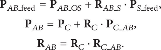
Thus,

Nine feeds move on a focus surface to track the celestial sources. So the

The coordinate rotation matrix

where cϕ presents cos ϕ, sϕ presents sin ϕ, ϕ and φ are azimuth angles, and θ is pitch angle.
The coordinate rotation matrix

where ca presents cos a, sa presents sin a, a is pitch angle around X-axis, andb is pitch angle around Y-axis.
The coordinate rotation matrix
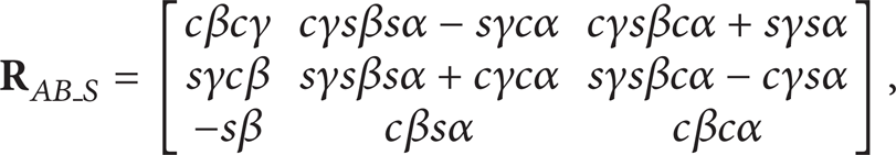
where cα presents cos α, sα presents sinα, α is yaw angle, β is pitch angle, and γ is roll angle. During the pose planning of the feed support system, the Stewart manipulator remains the initial pose. So
2.3. Modeling of the Six-Cable Driven Parallel Manipulator
Figure 5 is the six-cable driven parallel manipulator of FAST, and two coordinates are used: inertial frame ℜ:O − XYZ and moving frame ℜ C :O C − X C Y C Z C . B i (i = 1, 2,…, 6) are the connected points of the cables and support towers, and A j (j = 1, 2, 3) are the connected points of the cables and focus cabin.

Description of the six-cable driven parallel manipulator. (a) Coordinates of the six-cable driven parallel manipulator. (b) Parameters of the six-cable driven parallel manipulator.
For analyses, the symbols used in this section are defined as follows:

where
Assuming

where
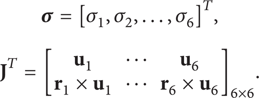
By introducing catenary equation of a single cable [12], which has been deeply researched and widely applied in architecture, the real cable length and tension can be calculated by using iterative algorithm. The specific solving process has been clearly explained in some references [13, 14]. The cable tensions of the six-cable driven parallel manipulator should satisfy the following:
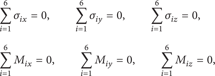
where ∑i = 16σ ix = 0 is the tension in X-direction of the six-cable driven parallel manipulator and ∑i = 16M ix = 0 is the torque in X-direction of the six-cable driven parallel manipulator.
3. Pose Planning Method of the Feed Support System
3.1. Pose Planning Function of the Feed Support System
Poses of the nine feeds are redundantly controlled by both the six-cable driven parallel manipulator and A-B rotator.
For the six-cable driven parallel manipulator of the feed support system, tension status is vital for whole system performances including usable workspace, positioning accuracy, and vibration. The six-cable driven parallel manipulator may not be stably controlled due to a small cable tension. However, cable tension closely relates to the pose angle of the six-cable driven parallel manipulator. On the other hand, the A-B rotator is a rigid mechanism, and its stability and accuracy can be improved by small pose angle.
Hence, for enhancing stability and accuracy of the feed support system, we change the pose planning problem to a pose angle optimization problem.
Firstly, we set up a pose angle optimization function of the six-cable driven parallel manipulator.
Based on the requirements of astronomical observations, the positions and poses of the nine feeds are given. The position and azimuth angle of the six-cable driven parallel manipulator are definite for matching the position of the nine feeds. In theory, pitch angle of the six-cable driven parallel manipulator should be equal to the tracking angle of the feeds. However, pitch angle relates to the cable tensions, and cable tensions relate to the stable control of the six-cable driven parallel manipulator. Therefore, we use the pitch angle as an optimization parameter for enhancing controllability of the six-cable driven parallel manipulator.
Tension controllability generalized volume function is adopted to evaluate controllability of the six-cable driven parallel manipulator:
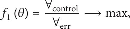
where θ is the pitch angle of the six-cable driven parallel manipulator.
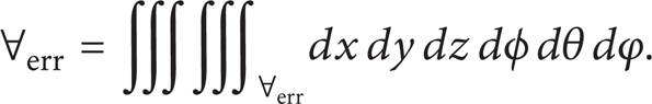
In (12), ∀ err is the allowed terminal error space and ∀control is defined as the controllable space of the six-cable driven parallel manipulator in its terminal error space ∀ err .
Suppose the position and pose of the six-cable driven parallel manipulator are (x0, y0, z0, ϕ0, θ0, φ0) T and allow terminal error of moving platform to be (εx, εy, εz, εϕ, εθ, εφ) T , which is expressed as

So the terminal error space ∀ err of moving platform can be defined as

The generalized volume of the ∀ err is
Supposing the pose of the six-cable driven parallel manipulator is (x c , y c , z c , ϕ c , θ c , φ c ), when cable tension σ i satisfies the tension condition, the six-cable driven parallel manipulator is controllable at that pose. So,
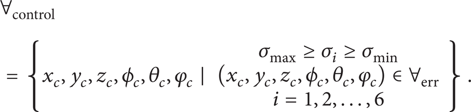
The generalized volume of ∀control is
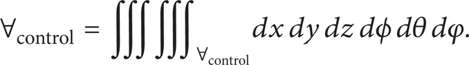
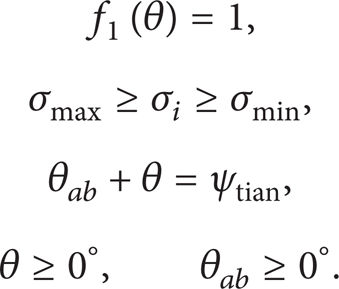
When f1(θ) is close to 0, it means the six-cable driven parallel manipulator has great chance to lose control. Otherwise, when f1(θ) is 1, it means the six-cable driven parallel manipulator is fully controlled with uniform cable tensions.
Secondly, an optimization function is set up for the A-B rotator. Smaller pose angle can reduce the gravity center change of the feed support system, which decreases negative influence on control accuracy and stability of the feed support system. Thus, the pose planning function of the A-B rotator is

where θ ab is the pose angle of the A-B rotator and ψtian is the tracking angle of the nine feeds.
After optimization functions of the six-cable driven parallel manipulator and A-B rotator are set up as (12) and (18); we propose an optimization function of the feed support system as follow.
We hope the six-cable driven parallel manipulator is fully controlled in its workspace. So, f1(θ) is introduced as an optimization condition for the feed support system, and f1(θ) is 1. Then, f2(θ ab ) is set up as the optimization function

Pose planning constraint conditions are
3.2. Pose Planning Process of the Feed Support System
As shown in Figure 3(a), maximum tracking angle of the nine feeds is 40°, and the angle is realized by the six-cable driven parallel manipulator and A-B rotator. There are nine feeds on the moving platform of the Stewart manipulator. Moving workspace of the nine feeds is the focus surface.
Pose planning associates with the using feed. At the same time, pose planning also associates with the position of the using feed. So, as shown in Figure 6, pose planning process of the feed support system is as follows.
Determine the using feed, and the workspace of the using feed is the focus surface in Figure 3. The vectors
The Stewart manipulator remains the initial pose. So
Supposing initial pose angles of the six-cable driven parallel manipulator and A-B rotator are 0°, we can get the initial vector
Based on
Therefore, new vector
If the difference of

Pose planning process of the feed support system.
4. Simulation and Results
According to the pose planning method in Section 3, we can complete pose planning of the feed support system. In Figure 7, required workspace of the nine feeds, which is a focus surface, is presented as a sphere crown surface. The tracking angle ψtian of the nine feeds changes from 0° to 40°.

Workspace and tracking angle of the nine feeds.
For planning pose angles of the feed support system, parameters of the feed support system are given as follows.
Firstly, parameters of the six-cable driven parallel manipulator are given in Table 2.
Geometric parameters of the six-cable driven parallel manipulator.

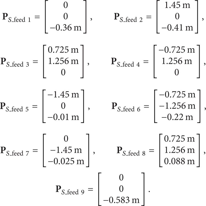
Secondly, nine feeds are fitted on the moving platform of the Stewart manipulator. The vectors of the nine feeds in the frame ℜ S :O S − X S Y S Z S are expressed as
Thirdly, the vector of the center of moving platform of the Stewart manipulator in the frame of ℜ AB :O AB − X AB Y AB Z AB is

Fourthly, the vector of the center of the A-B rotator in the frame of ℜ C :O C − X C Y C Z C is

Finally, during the pose planning of the feed support system, it defines that the maximum cable tension σmax is 35 kN and the minimum cable tension σ min is 12 kN. Optimization stop condition is Δ = 10 mm.
According to the parameters and pose planning process of the feed support system above and based on (19)–(20), pose angle extremum of the six-cable driven parallel manipulator and A-B rotator are listed in Table 3.
Pose planning extremum of the six-cable driven parallel manipulator and A-B rotator.

From Table 3, the results clearly indicate that optimized pose angle relates to the using feed. Taking Feed 1 as an example, the pose angle planning result of the feed support system is figured out in Figure 8.
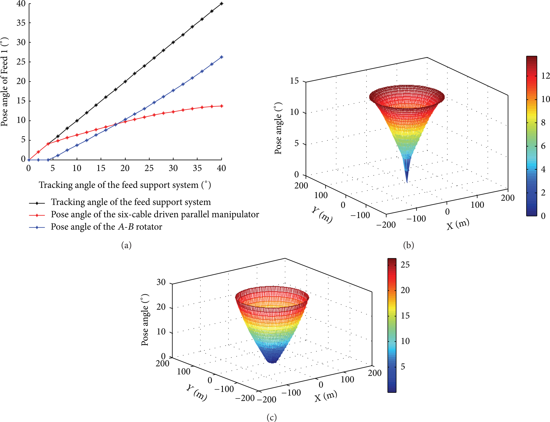
Pose planning results of the feed support system by using Feed 1 on the focus surface. (a) Pose angles of the feed support system. (b) Pose angle of the six-cable driven parallel manipulator. (c) Pose angle of the A-B rotator.
The optimization results represent f1(θ) = 1, and the cable tensions of the six-cable driven parallel manipulator should vary within σ min and σmax. Cable tension of one cable in the six-cable driven parallel manipulator is showed in Figure 9.

One cable tension of the six-cable driven parallel manipulator by using Feed 1 on the focus surface.
As shown in Figure 9, cable force varies from 13.39 kN to 31.82 kN. It shows that the cable tension is uniform and controllable of the six-cable driven parallel manipulator.
5. Conclusion
This paper addresses a pose planning method for the feed support system of FAST. Firstly, relationship of the feed support system components is described and the modeling of the feed support system is set up in detail. Secondly, considering the cable tension controllability of the six-cable driven parallel manipulator and gravity center change of the feed support system, a pose planning function is set up with constraint condition of the feed support system. Because pose planning results relate to the using feed and the position of the using feed, pose planning realization process is expressed step by step. Finally, based on the pose planning method in this paper, nine sets of optimized pose angles of the six-cable driven parallel manipulator and the A-B rotator are listed by using different feed. The results indicate that the pose angle of the six-cable driven parallel manipulator changes from 0° to 14° and the pose angle of the A-B rotator changes from 0° to 26.4°.
Conflict of Interests
The authors declare that there is no conflict of interests regarding the publication of this paper.
Footnotes
Acknowledgment
This research was financially supported by the National Natural Science Foundation of China (Nos. 11203048 and 11103046).