
Abstract
Planning of an appropriate bending sequence is one of the most important aspects in the processing of sheet metals as the appropriateness of the plan affects correct selection of bending tools and feasibility of bending processes. This study aims to propose a set of principles to be followed for the planning of bending sequences and selection of bending tools for 2.5D sheet metals. To this end, we first define basic bending patterns by characterizing each pattern with a set of operation rules. The sheet metal is then decomposed into a series of bending patterns that is in turn used in the planning of bending sequences. In order to select the bending tools, we combine the contours of each bending operation, choose appropriate bending punches from the bending-tool database, and then undertake an interference check with the bending contours.
1. Introduction
The bending process is one of the most important manufacturing processes in sheet metal prototyping, with the planning of bending sequences and selection of bending punches as critical steps within the process. In the past, these two activities relied on manual operations, but the rapid development of computer hardware and software in recent years has enabled this type of work to be performed with computer-aided methods. However, when confronted with a large number of bending steps, the numerous possibilities for bending sequence combinations will cause computational difficulty. Furthermore, when sequence planning involves multiple bending steps, it is bound to become rather complex. Although the task may be completed satisfactorily by using more bending punches or customized bending punches, the result may come with a tremendous rise in manufacturing costs and production time.
In the planning of bending sequences, attention must be paid to the relationship between the bending tools, the sheet metal, and the production equipment; it is a complex decision-making process [1]. A bending operation is generally applied on local areas of the sheet metal, but it greatly affects the entire profile of the sheet that in turn significantly influences the planning of the bending process. Therefore, it is beneficial to incorporate the geometric features of the sheet metal profile in the planning of bending sequences. A feasible bending sequence can be obtained by determining the bending priority of various profiles [2–5]. In planning a feasible bending sequence with multiple bending operations, a great number of applicable bending sequences need to be verified, which may lead to long computation times or even the possibility of computation explosion. One can employ the hard geometric constraints of the sheet metal and the branch-and-bound technique to obtain a feasible bending sequence plan [6, 7]. In addition, each bend can be defined as a virtual node. By referencing the relationship between each node and eliminating unnecessary node computation, a feasible bending sequence plan can then be obtained [8]. Furthermore, fuzzy theory can be applied in the planning of bending sequences by giving a corresponding weighting to each relevant rule during the bending process, which includes the following: the compound bend rule, parallel bend rule, shape determining bend rule, single face rule, and combined rotation rule. Calculations are then performed using a fuzzy matrix in order to obtain the best bending sequence [9, 10]. Some researchers used a genetic algorithm by incorporating punch matching into the sheet metal bending process to produce the best bending sequence plan [11, 12]. In planning the bending sequences, if there lacks a geometric model, then the relevant bending sequence constraints must be coded by hand, although the feasibility of this method cannot be guaranteed. By adopting a domain-specific geometric expert module that works on exact spatial representations of the workpiece, machine, and tools, along with utilizing the predefined constraint modules and the already-satisfied geometric constraints, these complex bending problems can be resolved [13]. Additionally, one can also find feasible bending sequence plans and bending punches by examining the relationships between the constraints for selecting bending punches and those for the checking of sheet metal contours [14]. To use the fewest and most common bending punches, one can parameterize the profiles of the bending tools and compare them to the geometric shape of the sheet metal in obtaining the applicable bending punch profiles [15]. Furthermore, the profile change of the sheet metal during the bending process may cause a bending punch to collide with the sheet metal. To avoid this, a spatial representation technique can be adopted to verify the possibility of a collision between a sheet metal and a bending punch [16].
A summary of the above research on bending sequence planning finds that a majority of the planning methods incorporate the geometric features of the sheet metal and the constraint conditions and give them various weight settings. However, finding the optimal weightings is not an easy task. A poor set of weightings can defeat the objective of enhancing the efficiency of the bending sequence planning and further lead to an undesirable planning result. To avoid the impact of the weight settings, our method does the following: it defines six basic bending patterns based on geometric profiles of the sheet metal, sets the bending process sequence of each bending pattern, performs bending recognition between the sheet metal and the bending patterns, decomposes the sheet metal into multiple bending patterns, and follows the specific operation procedures of each bending pattern. As for the selection of bending punches, a majority of the research summarized above involves interference checking between the preselected bending punches and the sheet metal profiles of each bending operation, followed by selection of the noninterference bending punches for the bending process. While this process may be completed via computational calculation, it still requires an unnecessarily long time. For the purpose of reducing computational time and eliminating the need to perform an interference check for every bend, we combine all the contours of all bending operations, define the final contour from the combined contours, and then select the bending punches from the bending-tool database. Therefore, in finding the appropriate bending punches, interference checking is performed with the final contour as opposed to every bend. The following sections will discuss in detail the methodologies for automatic planning of bending sequences and selection of bending tools.
2. Automatic Planning of Bending Sequences
As the number of bends increases, the number of possible bending sequences for a sheet metal part also increases. However, not every one of these bending sequences is workable, and the possibilities may include self-interference of the sheet metal part while bending, interference of the sheet metal part and the bending tool, and interference between the sheet metal part and the bending machine. If each possible sequence is to be verified, a very long computation time is to be expected. To solve this problem and to obtain a feasible bending sequence plan, we define six basic bending patterns to which we compare the desired sheet metal profile. The sheet metal is then transformed into a combination of a series of bending patterns, which follows the specific operation procedures of each bending pattern to complete the planning of the bending sequence.
2.1. Definition of the Six Bending Patterns
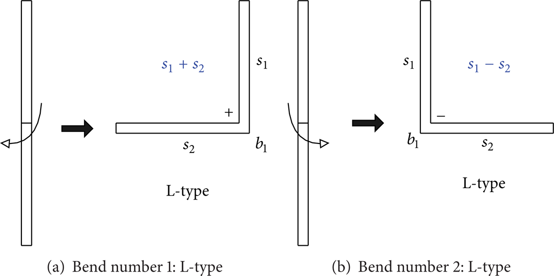
This study first defines six basic bending patterns. Each bending pattern consists of several bending surfaces and bending lines. The symbol “+” is used to denote two bending surfaces connected clockwise, while the symbol “−” denotes that the connection is counterclockwise, as shown in Figure 1. The six basic bending types are defined as follows.
There is only one possible shape after bending a flat sheet metal, as shown in Figure 2. This shape is similar to the letter “L”; thus, it is named the L-type bending pattern. This bending pattern consists of one bending line, b1, that connects two bending surfaces, s1 and s2. The symbol s1 + s2 denotes a clockwise connection, using the first surface as the base, while the symbol s1 − s2 denotes a counterclockwise connection.
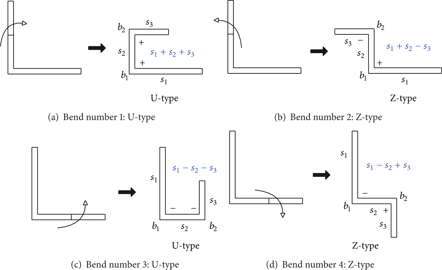
Two possible shapes result from applying a bend to an L-type sheet metal; these are shown in Figure 3. The first shape is similar to the letter “U” and thus it is named the U-type bending pattern, where two bending lines, b1 and b2, connect three bending surfaces, s1, s2, and s3. When all the connections are clockwise, the symbol s1 + s2 + s3 is used, whereas when all the connections are counterclockwise, the symbol s1 − s2 − s3 is used. The second shape is similar to the letter “Z”, and thus it is named the Z-type bending pattern, where two bending lines, b1 and b2, connect three bending surfaces, s1, s2, and s3. If the connection begins with a clockwise bend and is followed by a counterclockwise bend, then the symbol s1 + s2 − s3 is used; on the contrary, if it begins with a counterclockwise bend and is followed by a clockwise bend, then the symbol s1 − s2 + s3 is used.
Three possible shapes result from applying a bend to a U-type sheet metal, as shown in Figure 4. The first shape is a combination of the previously defined L-type and Z-type bending patterns. The second shape is similar to the letter “C”; thus it is named the C-type bending pattern, where three bending lines, b1, b2, and b3, connect four bending surfaces, s1, s2, s3, and s4. If all three bends are connected clockwise, then the symbol s1 + s2 + s3 + s4 is used; if they are connected counterclockwise, then s1 − s2 − s3 − s4 is used. The third shape is similar to the letter “P,” and so it is named the P-type bending pattern. The P-type bending pattern consists of three bending lines, b1, b2, and b3, that connect four bending surfaces, s1, s2, s3, and s4. There are two types of connections: (1) two clockwise connections followed by one counterclockwise connection, which is denoted by s1 + s2 + s3 − s4, and (2) two counterclockwise connections followed by one clockwise connection, which is denoted by s1 − s2 − s3 + s4.
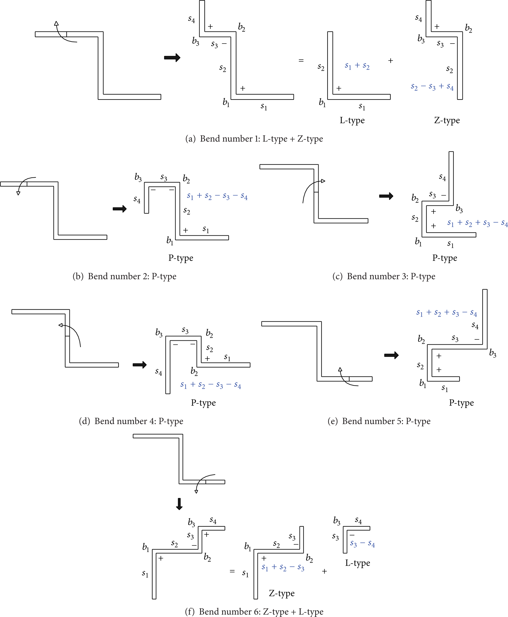
Two possible shapes result from applying a bend to a Z-type sheet metal, as shown in Figure 5. The first shape is a combination of the previously defined L-type and Z-type bending patterns. The second shape is the previously defined P-type bending pattern.
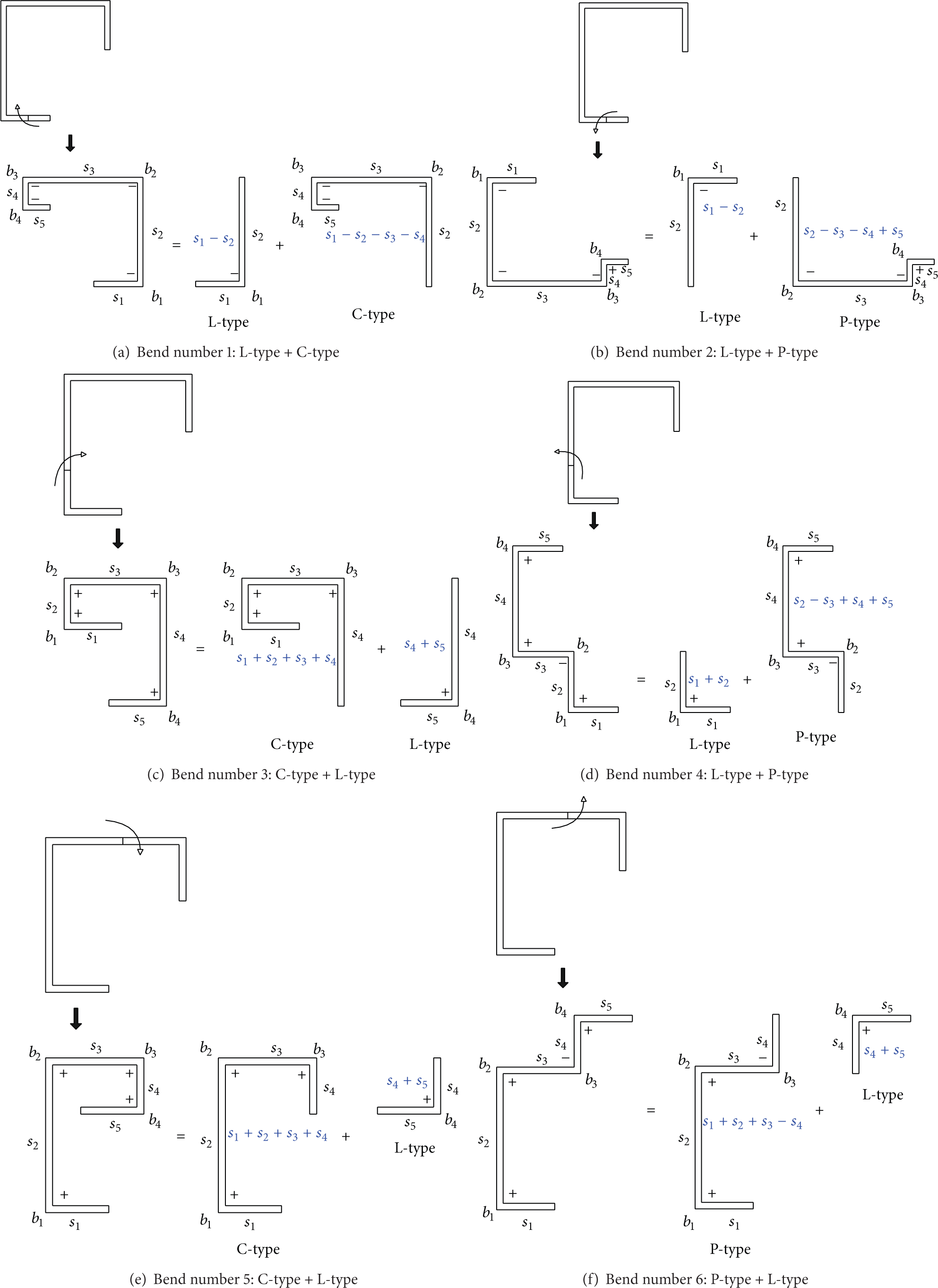
Two possible shapes result from applying a bend to a C-type sheet metal, as shown in Figure 6. The first shape is a combination of the previously defined L-type and C-type bending patterns. The second shape is a combination of the previously defined L-type and P-type bending patterns.
Three possible shapes result from applying a bend to a P-type sheet metal, as shown in Figure 7. The first shape is a combination of the previously defined P-type and L-type bending patterns. The second shape is a combination of two previously defined Z-type bending patterns. The third shape is a bending pattern that is not yet defined. Its shape is similar to the symbol “Ω,” and so it is named the Ω-type bending pattern, which is a combination of four bending lines, b1, b2, b3, and b4, that connect five bending surfaces, s1, s2, s3, s4, and s5. If the connection begins with a clockwise bend and is followed by two counterclockwise bends and then ends with a clockwise bend, then the symbol s1 + s2 − s3 − s4 + s5 is used. If the connection begins with a counterclockwise bend and is followed by two clockwise bends and then ends with a counterclockwise bend, then the symbol s1 − s2 + s3 + s4 − s5 is used.

Bending surfaces and bending lines for two bend types.
Resulting shapes after bending a flat sheet metal.
Resulting shapes after bending an L-type sheet metal.

Resulting shapes after bending a U-type sheet metal.
Resulting shapes after bending a Z-type sheet metal.
Resulting shapes after bending a C-type sheet metal.
Resulting shapes after bending a P-type sheet metal.
From the above descriptions, we can see that when performing a series of bends on a piece of sheet metal, regardless of the number of bends, the contour of the sheet metal can always be decomposed into a combination of six bending pattern types: L, U, Z, C, P, and Ω. Detailed illustrations, symbols, and bending sequences for these six bending patterns are listed in Table 1.
Schematic illustration of the six bending patterns.
2.2. Pattern Recognition of Sheet Metal Profile
In processing a sheet metal with the six bending patterns mentioned above, we first assign codes to the bending surfaces and their connection types. We then compare the resulting codes with the bending patterns in order to split the sheet metal into a variety of bending patterns. These are the steps.
Step 1. Determine if the codes contain an Ω-type bending pattern. If such a pattern is found, the codes associated with the bending pattern are extracted from the complete set of codes. Continue to process the remaining codes to find if there are any additional Ω-type bending patterns. Extract them if found. Repeat this step until all the codes are thoroughly processed.
Step 2. Determine if the remaining codes contain a P-type bending pattern. If so, extract it from the full set of codes. Continue to process the remaining codes for any additional P-type bending patterns. Extract them if found. Repeat this step until all the codes are thoroughly processed.
Step 3. Next, determine if the remaining codes contain C-type, U-type, Z-type, or L-type bending patterns. If any are found, the codes associated with the bending patterns are extracted. Repeat this step until all the codes are thoroughly processed.
When the process of pattern recognition is completed, a combination of various bending patterns will be obtained. Take the sheet metal in Figure 8 as an example; its bends can be represented as s1 + s2 − s3 − s4 − s5 + s6 + s7 − s8 − s9 − s10 + s11. Therefore, its connection codes are + − − − + + − − − +, and the process of pattern recognition is as follows.
Sheet metal with ten bends and its codes.
Step 1. Take the first code to the fourth code + − − − from the set of codes + − − − + + − − − + and compare them with the codes of Ω-type pattern − + + − and + − − +. There is no match. Next, take the second to fifth codes − − − + and compare them with the codes of Ω-type pattern. There is still no match. Next, take the third to sixth codes − − + + and compare them with the Ω-type codes. There is still no match. Next, take the fourth to seventh codes − + + − and compare them with the Ω-type codes. The result is a match. An Ω-type bend is thus obtained and the fourth to seventh codes − + + − are removed from the set. The remaining codes are therefore divided into two groups, with the first group being + − − and the second − − +. Since the first group has already been compared with the Ω-type codes, it is skipped in the comparison process. The second group is compared with Ω-type codes, and no match exists. Therefore, these codes + − − and − − + are kept for the next comparison. The procedure is illustrated in Figure 9(a).

Code comparison and pattern extraction for the sheet metal in Figure 8.
Step 2. Compare the remaining codes + − − and − − + with P-type codes − − +, + + −, − + +, and + − −. First, take the codes of the first group + − − and compare them with P-type codes. There is a match, so a P-type bending pattern is obtained. Next, take the codes of the second group − − + and compare them with P-type codes. The result finds a match, so one more P-type bending pattern is obtained. Figure 9(b) illustrates the procedure.
From Steps 1 and 2, one can find that the sheet metal is a combination of one Ω-type bending pattern s4 − s5 + s6 + s7 − s8 and two P-type bending patterns s1 + s2 − s3 − s4 and s8 − s9 − s10 + s11. This is shown in Figure 10.
Bending patterns found for the sheet metal in Figure 8.
2.3. Generation of Feasible Bending Sequences
After the sheet metal is split into a variety of bending patterns, we consider the order of the bending patterns. As the bending patterns with multiple bends are more likely to require greater space during the manufacturing process, there will be a higher risk of interference if they are arranged in the latter stages of the bending operation. Hence, we group bending patterns based on the total number of bends: Ω-type pattern with four bends, P- and C-type patterns with three bends each, Z- and U-type patterns with two bends each, and L-type pattern with one bend. Additionally, for P- and C-type patterns that have three bends, the P-type pattern is bent prior to the C-type pattern, as the P-type pattern requires less bending space; similarly, for Z- and U-type patterns, the Z-type pattern is bent prior to the U-type pattern. Hence, the following sequence is derived: Ω-type → P-type → C-type → Z-type → U-type → L-type; that is, Ω-type is bent first, then P-type, and so forth, ending with L-type.
Taking the sheet metal in Figure 8 as an example, if the bending sequence is arranged without adhering to proper bending rules and two P-type bends are performed before the Ω-type bend, then interference will occur at the ninth bend operation; this is shown in Figure 11. However, by following the bending rules described in this study, performing one Ω-type bend followed by two P-type bends, the bending operation can be completed with only one bending tool without any interference, as shown in Figure 12.

Improper bending sequence.

Bending sequence with no interference.
3. Automatic Selection of Bending Tools
Using the least amount of bending punches during the bending process reduces not only the time of the bending processes, but also the operation costs. To attain this goal, we first combine, respectively, the left and the right contours of each of the bending operations. Rules of thumb in sheet metal bending are then used to convert the contours into a final shape ready for selection of bending punches.
3.1. Use of a Single Bending Tool
The selection of bending punches for the sheet metal in Figure 8 is as follows.
Step 1. Using the bending line as the split point, each of the bending contours is split into left and right contours. Then, all the left and right contours are combined, respectively, and codes are assigned to the origin point, the turning points, and the endpoints. Figure 13 shows the procedure of generating the combined contour to the left of the bending line, while Figure 14 shows that for the right.
Procedure for generating the combined left contour for the sheet metal in Figure 8.

Procedure for generating the combined right contour for the sheet metal in Figure 8.
Step 2. When selecting the final contour, follow the principle of selecting the one with the smallest possible opening, so that the smallest bending tool can be chosen and the tool can be used for the entire bending process with the least chance of interference. The method of determining the final contour to the left of the bending line is as follows. Use the origin point as the starting point and connect it to the turning point to obtain the first line segment. Then use the turning point as the starting point for the next line segment, and connect it to the next turning point that can help in producing a comparably smaller opening of the line segment. The detailed procedure is as follows.
Determine if a turning point may be connected by proceeding from the starting point in the clockwise direction. If so, then proceed in the clockwise direction to connect the next turning point. Repeat this process until there are no more contours to follow in the clockwise direction.
Determine if a turning point may be connected by proceeding in the forward/straight direction. If so, then proceed in the forward direction when connecting the next turning point. Repeat this process until there are no more contours to follow in the forward direction.
Determine if a turning point may be connected by proceeding in the counterclockwise direction. If so, then proceed in the counterclockwise direction to connect the next turning point. Repeat this process until there are no more contours to follow in the counterclockwise direction.
Repeat the steps in (1), (2), and (3) until an endpoint is reached and the final contour to the left side of the bending line is acquired.
Regarding the sheet metal in Figure 8, its combined contour to the left of the bending line is explained as follows. Use the bending point L0 as the starting point, and connect to L1; go straight to L3 and then straight again to connect to L4; connect to L2 clockwise; connect to L5 counterclockwise, and go counterclockwise again to L7; connect L9 clockwise; connect L8 clockwise; connect L10 counterclockwise; connect L11 counterclockwise; connect L13 clockwise; proceed in a straight line to L16 and again in a straight line to L21. Because L21 is the endpoint of this contour and it does not intersect with any other contours, the final left contour is composed of line segments in the sequence L0L1, L1L3, L3L4, L4L2, L2L5, L5L7, L7L9, L9L8, L8L10, L10L11, L11L13, L13L16, and L16L21, as shown in Figure 15(a).

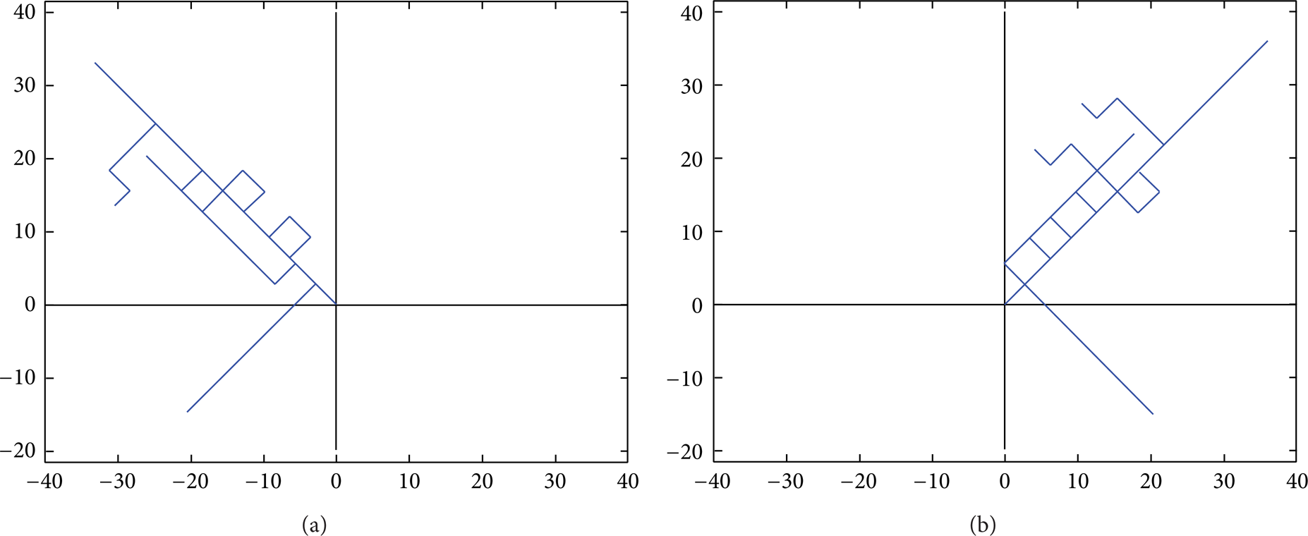
Final left and final right contours generated for the sheet metal in Figure 8.
The method of determining the final contour to the right of the bending line is similar to that for the final left contour but differs in the sequence of directions. The selection follows the sequence counterclockwise, straight, and then clockwise. The detailed procedure is as follows. Use the bending point R0 as the starting point and go straight to connect R2; go counterclockwise to connect R1; go clockwise to connect R3; go straight to connect R6 and straight again to connect R10; go straight to connect R13; go counterclockwise to connect R9; go counterclockwise to connect R7; go clockwise to connect R4. Because R4 is the endpoint of this contour and it does not intersect any other contours, there is no need to connect to other endpoints. Thus, the final right contour is composed of line segments in the following sequence: R0R2, R2R1, R1R3, R3R6, R6R10, R10R13, R13R9, R9R7, and R7R4. This is shown in Figure 15(b).
Step 3. Combining the final left and the final right contours yields the final contour shown in Figure 16.

Final contour generated for the sheet metal in Figure 8.
Step 4. Compare the final contour with the profiles of bending punches in the bending-tool database (Figure 17). The comparison shows that only one bending punch is needed (Figure 18) to complete the entire bending operations of the bending process.

Database of bending punches [17].
Bending punch selected for the sheet metal in Figure 8.
3.2. Use of Multiple Bending Tools
As another example, we consider the sheet metal part in Figure 19. Its bending punch selection is as follows.
Sheet metal with twelve bends and its codes.
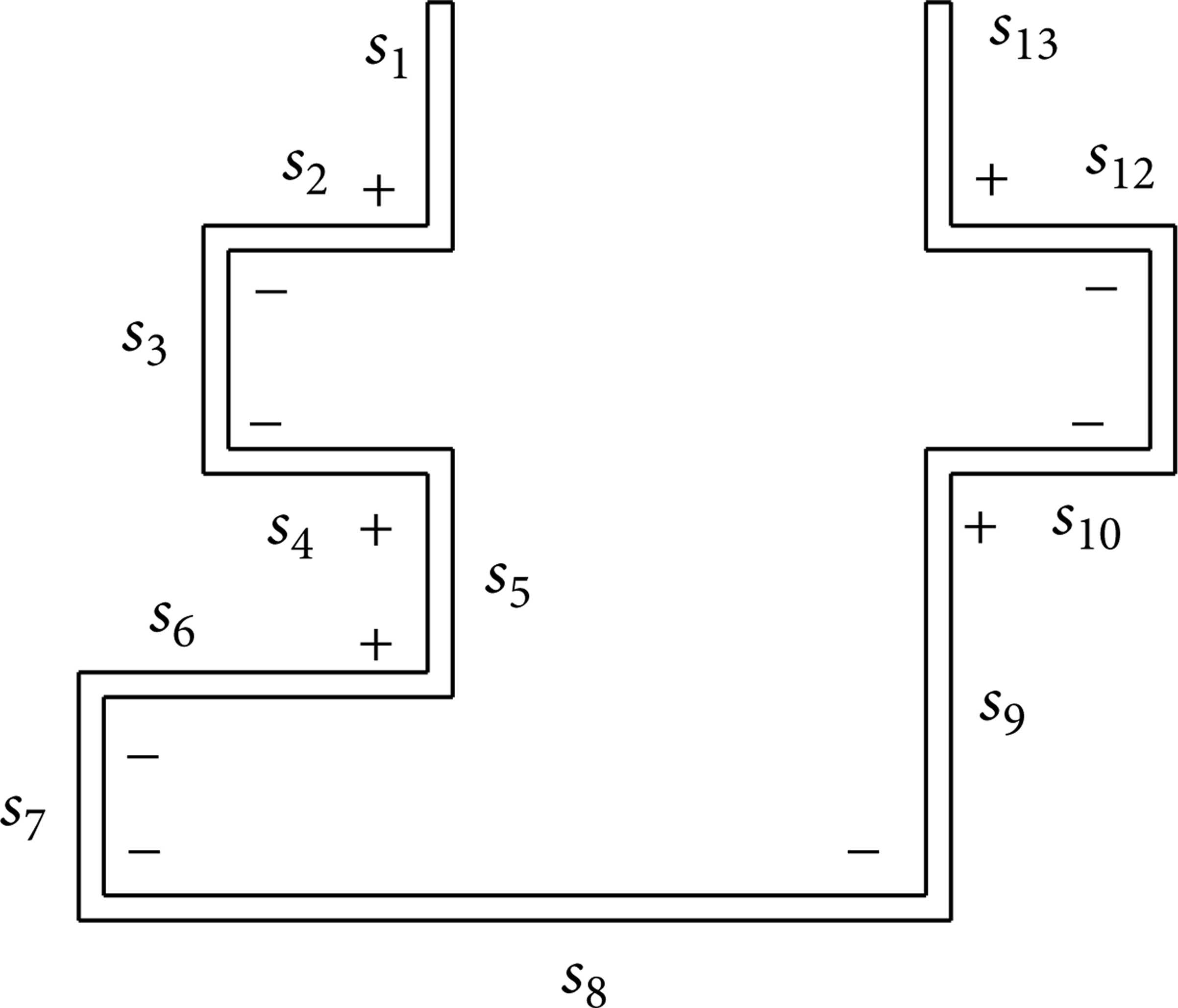
Step 1. The codes of the sheet metal are s1 + s2 − s3 − s4 + s5 + s6 − s7 − s8 − s9 + s10 − s11 − s12 + s13, and its connection codes are + − − + + − − − + − − +. After code comparison and pattern extraction, the following bending patterns can be found: two Ω-type bends, s1 + s2 − s3 − s4 + s5 and s9 + s10 − s11 − s12 + s13; one P-type bend, s5 + s6 − s7 − s9; and one L-type bend s8 − s9. These are shown in Figure 20.

Bending patterns found for the sheet metal in Figure 19.
Step 2. Perform sequence planning for the bending process: the two Ω-type bend sequences, s1 + s2 − s3 − s4 + s5 and s9 + s10 − s11 − s12 + s13, are prioritized, followed by the P-type bend. Lastly, the L-type bend, s8 − s9, is arranged, as shown in Figure 21.

Procedure for sequence planning for the sheet metal in Figure 19.
Step 3. Combine the contours of each bending operation on the left and right sides of the bending line, and assign codes to all origin points, turning points, and endpoints, as seen in Figure 22.

Codes assigned for the combined contours of the sheet metal in Figure 19.
Step 4. Following the bending contour principle mentioned above, we obtain the final left contour L3L8, L8L2, L2L6, L 6 L4, L4L10, L10L7, L7L5, L5L1, and L1L0 and final right contour R0R2, R2R1, R1R3, R3R15, R15R18, and R18R23, as shown in Figure 23.
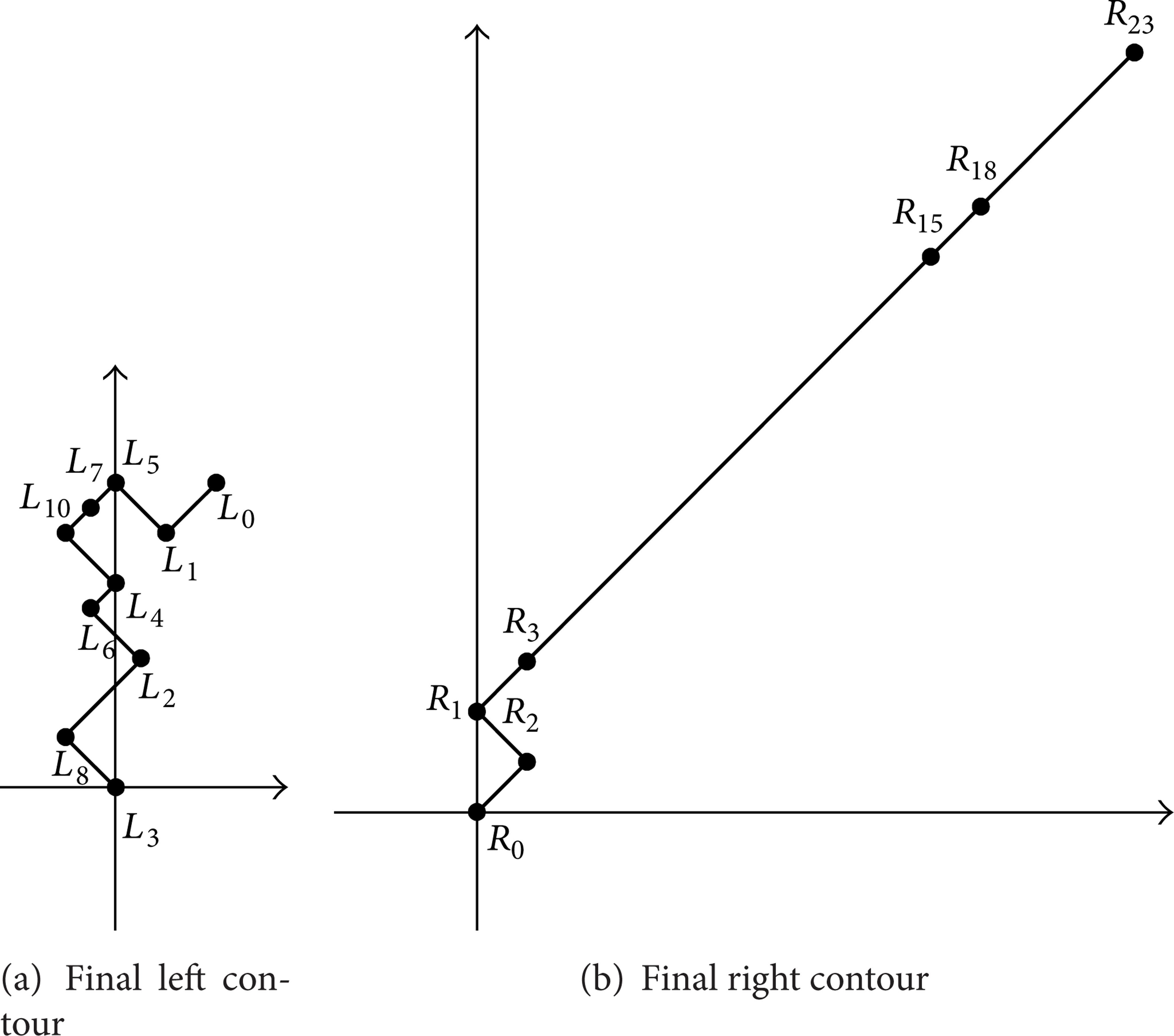
Final left and final right contours generated for the sheet metal in Figure 19.
Step 5. Combine the final left and right contours to obtain the contour in Figure 24, and compare the combined final contour with the profiles of bending punches in the bending-tool database. The comparison is unsuccessful in finding a suitable bending punch; that is, one cannot complete all the bending operations with one bending punch. As a result, we remove the last bending operation (the 12th) from the bending process and compare the remaining final contour (as shown in Figure 25(a)) with the profiles of bending punches in the bending-tool database. Again, the comparison does not yield a suitable bending punch, so the profile of the 11th bending operation is also removed from the final contour. Again, compare the remaining final contour (as shown in Figure 25(b)) with the profiles of bending punches in the bending-tool database. The results show that one bending punch can be used to complete the bending process from the 1st to the 10th operations (as shown in Figure 26).

Final contour generated for the sheet metal in Figure 19.

(a) Final contour after removing the 12th bend contour. (b) Final contour after removing the 11th and 12th contours.

Bending punch found for the 1st to the 10th bending operations.
Step 6. Find the bending tool for the 11th and 12th bending operations. Combine the 11th and 12th bending contours to the right and left of the bending line to obtain the combined contours (Figure 27) and their relevant codes. Then, follow the bending contour principle mentioned above to acquire the final left contour L2L6, L6L3, L3L7, L7L4, L4L8, L8L5, L5L1, and L1L0 and the final right contour R0R2, R2R1, R1R3, R3R4, R4R6, R6R 5 , R5R7, R7R8, and R8R9, as shown in Figure 28.

Combined contours of the 11th and 12th bending operations.

Final left and final right contours of the 11th and 12th bending operations.
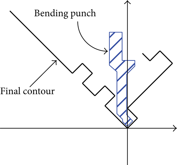
Step 7. Combine the final left and the final right contours to acquire the combined final contour in Figure 29, and then compare the final contour with the profiles of bending punches in the bending-tool database. The result finds no suitable bending punch, so we must proceed to design a bending punch based on the combined final contour. The bending punch shown in Figure 30 is the resulting punch to be used in the 11th and 12th operations of the bending process.

Final contour of the 11th and 12th bending operations.

Bending punch designed for the 11th and 12th bending operations.
4. System Implementation
To verify the feasibility of the methodology proposed in this study, we developed a prototype system using MATLAB for experimentation with several real life examples. In the first place, Pro/Engineer, a well-known commercial package for geometric modeling, was adopted to create a 3D CAD model of the sheet metal part, and the default bending allowance provided by the software package was used to flatten the sheet metal into a 2D model. Once the two sets of geometric data were extracted, a MATLAB program and the method proposed by this paper were incorporated to find the solution of bending sequences with working press brake tooling.
Figure 31 shows the flow chart of the implemented system. First, an input sheet metal is compared with the bending patterns. The pattern recognition (code comparison and pattern extraction) method is used to find bending patterns. The bending sequence with the obtained bending patterns is then generated, and the sequence is in turn used in the contour calculation. Finally, a suitable bending punch is selected.
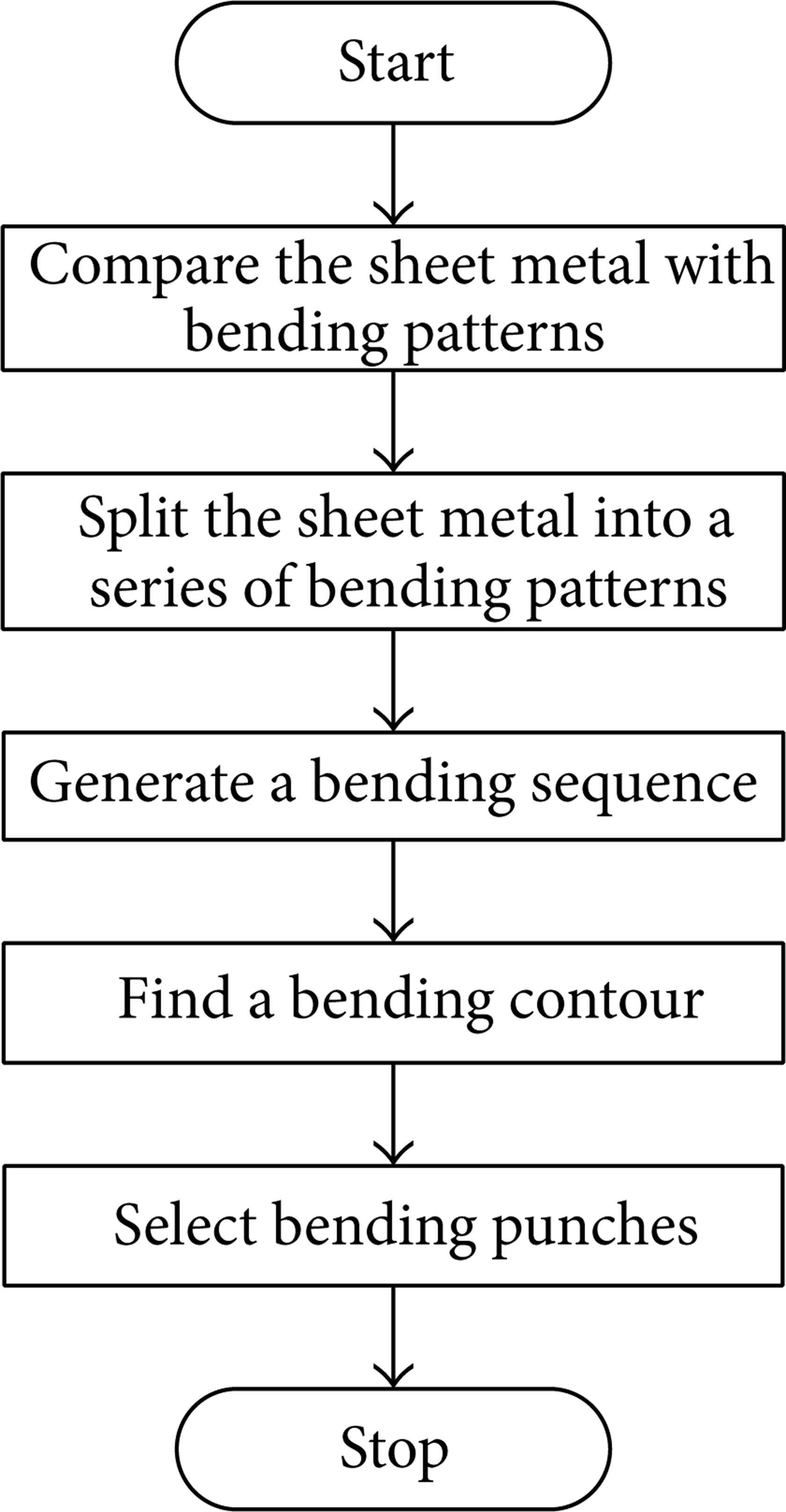
Flow chart of the implemented system.
Consider the sheet metal part in Figure 32: as it requires V-bending with a small bending radius, it is simplified to straightedge bends after its 3D sheet metal profile is imported. Additionally, the sheet thickness is small in comparison to the sheet profile and thus may be neglected such that we can consider the sheet metal to be composed of multiple planes. This simplified 2.5D sheet metal data is then processed by the system, which generates the bending sequence as shown in Figure 33. Next, the left contour of each bending operation is superimposed to form the contour in Figure 34(a), and the right contour of each bending operation is superimposed to form the contour in Figure 34(b). These contours are processed by the method discussed in Section 3, giving the final contour as shown in Figure 35. An interference comparison between the final contour and each of the bending punches in the bending-tool database is then performed. Lastly, a suitable bending punch is selected, as shown in Figure 36.

Preprocessing of a 3D sheet metal.

Bending sequence generated by the implemented system.
(a) Superimposed contour to the left of the bending line, (b) superimposed contour to the right of the bending line.

Final contour found by the implemented system.

Bending punch generated by the implemented system.
5. Conclusions
Traditionally, the planning of bending sequences and the selection of bending punches are undertaken by a sheet metal process planner, who, based on his or her own experience, repeatedly tests and verifies each bending sequence operation with the required bending punch for each operation in order to determine the usable bending punches. However, for sheet metals with many bends or with unique profiles, it is fruitless to use human labor for such planning and selection. Even with computational calculation, arriving at a feasible sequence planning result and a suitable bending punch is a long process.
Our study proposes a method that saves time and achieves a feasible model to follow when planning the bending sequence of sheet metal. We first define six types of bending patterns, L-, Z-, U-, P-, C-, and Ω-type, for sheet metals, followed by their bending priorities; pattern recognition (code comparison and pattern extraction) is then performed for the six bending patterns and the desired profile of the sheet metal. Following the defined prioritization, we plan the bending sequences for the bending patterns obtained from the extraction process. After the bending sequences are determined, we use the method of splitting by the bending line and grouping, to find a usable bending punch. This method not only significantly reduces the time spent on planning the bending sequences for sheet metals, but also allows quick determination of a reduced number of required bending punches.
Conflict of Interests
The authors declare that there is no conflict of interests regarding the publication of this paper.