
Abstract
An analytical model on electromechanical coupling coefficient and the length optimization of a bending piezoelectric ultrasonic transducer are proposed. The piezoelectric transducer consists of 8 PZT elements sandwiched between four thin electrodes, and the PZT elements are clamped by a screwed connection between fore beam and back beam. Firstly, bending vibration model of the piezoelectric transducer is built based on the Timoshenko beam theory. Secondly, the analytical model of effective electromechanical coupling coefficient is built based on the bending vibration model. Energy method and electromechanical equivalent circuit method are involved in the modelling process. To validate the analytical model, sandwich type piezoelectric transducer example in second order bending vibration mode is analysed. Effective electromechanical coupling coefficient of the transducer is optimized with simplex reflection technique, and the optimized ratio of length of the transducers is obtained. Finally, experimental prototypes of the sandwich type piezoelectric transducers are fabricated. Bending vibration mode and impedance of the experimental prototypes are tested, and electromechanical coupling coefficient is obtained according to the testing results. Results show that the analytical model is in good agreement with the experimental model.
1. Introduction
Although the developments of computer science and new software techniques have greatly promoted the designing, optimization, and characterization of piezoelectric ultrasonic transducers, there are still lots of problems existing in piezoelectric ultrasonic transducer technology over the past few decades. Recently, various valuable research attempts have been focused on piezoelectric micromachined transducers which are of high piezoelectric coupling and based on a PZT thin film or PVDF [1–3]. However, the sandwich piezoelectric ultrasonic transducers, which are widely used in ultrasonic motor (USM), are still of significant value to research on.
Existing modeling methods of piezoelectric ultrasonic transducers are mostly accomplished based on equivalent circuit methods, analytical approaches, and finite element modeling. Currently, researchers have committed themselves to the structures innovation by means of FEM technique [4–6] which is labor-intensive and limited individual transducers to achieve their optimized size [7]. Most of the existing analytical models are vibration models and equivalent circuit models [8–10]. For instance, Yamada et al. derived a detailed equivalent network representation for thickness vibration modes in piezoelectric plates [11]. In addition, Perçin has attempted to formulate a circuit model for micromachined piezoelectric ultrasound transducers [12]. Moreover, Hagood and McFarland derived an analytical model of a piezoelectric rotary ultrasonic transducer, with which natural frequencies and mode shapes are obtained [13].
Because of reasons like the irrationality of structure design and unreasonable placement of PZT, electromechanical coupling efficiency of the transducer is comparatively low, which calls for the necessity of researching on the electromechanical coupling model of piezoelectric ultrasonic transducer. An enhanced equivalent circuit model of a rotary traveling wave piezoelectric USM is derived by El Ghouti and Helbo [14]. They highlight the importance of the electromechanical coupling coefficient, which is responsible for the electrical to mechanical energy conversion. Recently, Sammoura et al. develop an equivalent network of a piezoelectric micromachined ultrasonic transducer whose effective coupling coefficient of theoretical model and simulated model is 14.5% and 18.5%, separately [15]. Liu et al. have noticed the importance of electromechanical coupling coefficient, and they proposed several prototype piezoelectric ultrasonic transducers whose electromechanical coupling coefficients are around 20% [4, 16, 17].
In contrast to the previous works, we find that the electromechanical coupling models for the beam-like sandwich type piezoelectric ultrasonic transducers have seldom been noticed. However this type of transducer is widely used in many applications. As such, we derive an analytical electromechanical coupling model of a bending piezoelectric ultrasonic transducer, and the length optimization is obtained. PZT-4 provided by Jingdezhen Tonghui Electronics Limited Company is chosen as the stimulating ceramic. There are 8 PZT ceramics sandwiched between four thin electrodes, and the PZT elements are clamped by a screwed connection between fore beam and back beam. The objective of the present work is to derive the analytical model of effective electromechanical coupling coefficient by extracting the parameters from the electromechanical equivalent circuit representing the sandwich piezoelectric ultrasonic transducer and find out the length optimization which can guide the designing of the transducer. In addition, validation of the analytical model is conducted by fabricating the prototype transducers.
2. Structure of Sandwich Type Piezoelectric Ultrasonic Transducer
Figure 1(a) shows the structure of sandwich type piezoelectric ultrasonic transducer. The transducer is composed of a fore beam, piezoelectric ceramics, a back beam, an insulation gasket, and electrodes. L1 and L2 represent the axial sizes of the fore beam and the back beam separately. t represents the thickness of a single piezoelectric ceramic chip. The cross section of the piezoelectric transducer is a rectangle with B × D being the side lengths of it. There are 8 PZT ceramics in the transducer, and their distribution is shown in Figure 1(b). We mark the PZT ceramics with number 1 to number 8. Among them ceramics 1, 3, 6, and 8 are one group, and the rest of the ceramics are the other group. The ceramics are thickness-polarized, and the two groups of ceramics are polarized in opposite directions. Material parameters of the transducer are shown in Tables 1 and 2.
Material parameters of fore beam and back beam.

Material parameters of piezoelectric ceramics.

Sandwich type piezoelectric transducer.
3. Analytical Model of Effective Electromechanical Coupling Coefficient
Bending vibration model of sandwich type piezoelectric transducer is first built based on Timoshenko beam theory. Elastic energy, electrical energy, and electromechanical energy of the piezoelectric transducer are obtained based on the bending vibration model. In addition, equivalent circuit model of the transducer is built. The parameters in equivalent circuit can be extracted corresponding to the energies of transducer. Then effective electromechanical coupling coefficient is obtained based on equivalent circuit theory.
3.1. Bending Vibration Model of Sandwich Type Piezoelectric Transducer
Euler-Bernoulli beam theory is generally used to build the bending vibration model for beam-like structure. However, the Euler-Bernoulli beam is of good accuracy only for slender beams. Timoshenko (1921, 1922) [18, 19] proposed a beam theory which considers the effect of shear as well as the effect of rotation, which is of good accuracy for nonslender beams and for high-frequency responses where shear or rotary effects cannot be neglected. It is obvious that the transducer in this work is a nonslender beam. The fourth order differential equation for the amplitude y in the two-coefficient Timoshenko theory is

which is separable for a normal mode, with G and E being the shear and Young modulus, respectively, ρ being the density, A being the cross-sectional area of the beam, I being the moment of inertia, r2 = I/A being the rotation radius of the cross section, and κ being the Timoshenko coefficient, for rectangular cross section, κ = 0.833.
Four intermediate variables are defined as

Then the bending vibration model of the transducer can be obtained as

where Y i is the lateral amplitude, M i is the bend moment, ψ i is the angle of bend moment, and Q i is the shearing force. The subscript i = 1, 2, p represents fore beam, back beam, and piezoelectric ceramic beam separately.
Assembling the three parts, boundary conditions of displacement and section force are obtained and listed in Table 3. The boundary conditions also can be expressed in system of linear homogeneous equations:

where R is a 12 × 12 characteristic matrix and C = [C11, D11, C12, D12, C21, D21, C22, D22, Cp1, Dp1, Cp2, Dp2]T is a coefficient vector. Resonance frequency of the transducer is found numerically by scanning the determinant of matrix R as a function of frequency. When the determinant equals 0, resonance frequency is obtained.
Boundary conditions.
3.2. Energies of Sandwich Type Piezoelectric Transducer
Elastic energy, electrical energy, and electromechanical couple energy of the transducer are obtained in this part.
3.2.1. Elastic Energy of the Transducer
Elastic energy of the transducer consists of three parts. They are elastic energy of fore beam, elastic energy of back beam, and elastic energy of piezoelectric ceramics.
Figure 2 shows the working principle of a piezoelectric ceramic stimulated by a sinusoidal voltage U(τ). x1, x2, x3, x4, x5, and x6 represent the translational coordinates and rotational coordinates. u, v, and w represent the displacements in x1, x2, and x3.
Piezoelectric ceramic unit.
According to the Timoshenko beam theory, we have equations for the displacements in three coordinate directions:

where ψ p is the displacement in coordinate x5, which represents the angle of bend moment.
The bending vibration is a microstate vibration. Thus, among the strains, only S3 and S5 are considered. The relationships between the displacements and strains are shown in
where y p is the displacement of piezoelectric ceramics on the y-axis.
Elastic energy density of the piezoelectric ceramic can be expressed in

where T3, T5 are the stresses.
Substituting the piezoelectric equations

There are four terms appearing on the right side of (8), among which the first two terms represent pure elastic energy of the piezoelectric ceramic and the remaining two terms represent the electromechanical couple energy of the piezoelectric ceramic. Thus the pure elastic energy density of the piezoelectric ceramic is
Substituting (6) into (9), pure elastic energy density of the piezoelectric ceramic can be expressed as shown in

Elastic energy of the two ceramics in interval [L1, L1 + t] can be obtained by a volume integration shown in

where B, D, and t are the structure parameters of the transducer.
As shown in Figure 1, there are 8 piezoelectric ceramic chips in total. Therefore, the entire elastic energy of the piezoelectric ceramics should be the summation of the elastic energies in the four intervals ([L1, L1 + t], [L1 + t, L1 + 2t], [L1 + 2t, L1 + 3t], and [L1 + 3t, L1 + 4t]). The whole elastic energy of the piezoelectric ceramics is finally calculated by setting the integrating range as [0,4t] shown in

In the same way, elastic energy of fore beam and back beam also can be obtained by volume integrations of elastic energy density. The following equation shows the energy density of the fore beam:

where E1 is the elastic modulus of fore beam, y1 is the lateral displacement of fore beam, and ψ1 is the angle of bend moment.
After volume integration, (14) shows the result of elastic energy of the fore beam. And elastic energy of back beam can be obtained with the integration shown in (15):

Finally, elastic energy of the piezoelectric transducer is obtained by adding up the three parts of elastic energies shown in

3.2.2. Electrical Energy of the Transducer
Electrical energy of the transducer is converged in piezoelectric ceramics. The following equation shows the expression of electric energy density:
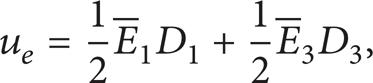
where
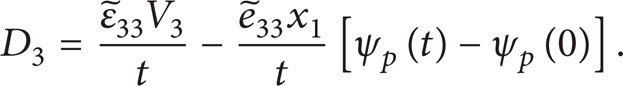
The piezoelectric ceramics are polarized in x3 direction and the bending vibration is a microstate vibration. Thus we assume that
According to the piezoelectric equations and the relationship between stresses and strains in Timoshenko theory given by

the electric displacement vector D3 can be expressed in

Here we assume that

where V3 is the excitation voltage.
Substituting (20) into (19), we obtain the expression of the electric displacement vector D3 given by
And the electric energy density of the piezoelectric ceramic can be obtained by substituting (20) into (17) as shown in
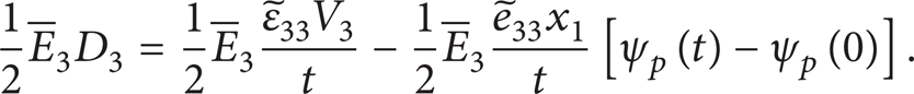
There are two terms appearing on the right side of (22), among which the first term represents pure electric energy density and the second term represents electromechanical couple energy density. The pure electric energy of a single piece of piezoelectric ceramic can be obtained by a volume integration of the first term shown in

Considering the fact that the excitation sinusoidal voltages of the 8 piezoelectric ceramics are of the same peak value, the pure electric energy of the sandwich type piezoelectric transducer can be written as

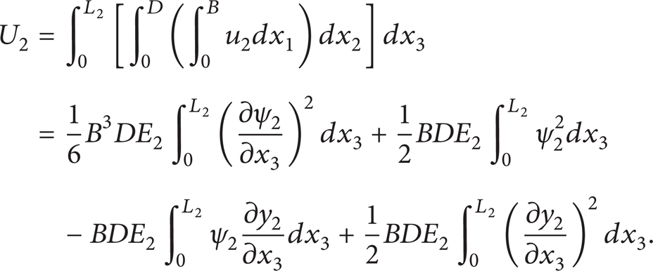
3.2.3. Electromechanical Couple Energy of the Transducer
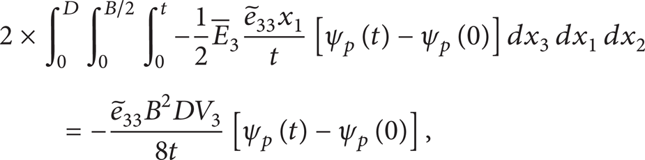
The second term of (22) represents electromechanical couple energy density. And the electromechanical couple energy can be given by a volume integration of electromechanical couple energy density. Equation (25) shows the electromechanical couple energy of the ceramics in interval [L1, L1 + t]. Electromechanical couple energy of the entire transducer can be obtained by adding the electromechanical couple energy of the ceramics in intervals [L1, L1 + t], [L1 + t, L1 + 2t], [L1 + 2t, L1 + 3t], and [L1 + 3t, L1 + 4t] shown in (26):

3.3. Electromechanical Equivalent Circuit of Sandwich Type Piezoelectric Transducer
Figure 3 shows the electromechanical equivalent circuit of the piezoelectric transducer. The electromechanical equivalent circuit can be expressed in equations shown in

where j is the imaginary unit, V the excitation voltage, I the excitation current, F the mechanical force,
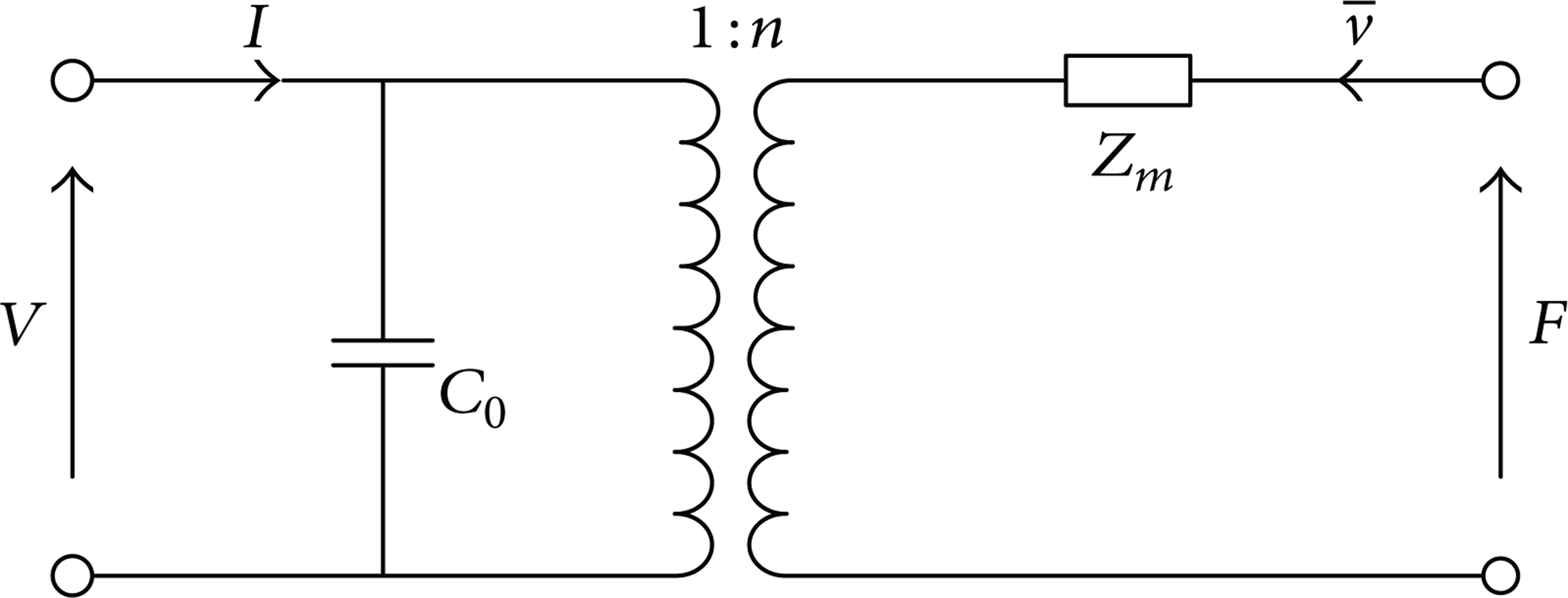
Electromechanical equivalent circuit.
In a piezoelectric transducer, V and I represent the electrical port and F and

where Q is the quantity of electric charge and
Adding up the two equations in (28), we obtain

There are two terms on the left side of (29). The first term represents the mechanical energy that the transducer obtained from exotic environment, and the second term represents the electric energy that the transducer obtained from the excitation power supply. On the right side of (29), the first term represents the pure mechanical energy of the transducer, the second and third terms represent the electromechanical couple energy, and the fourth term represents the pure electric energy of the transducer. The energies obtained in (29) are the different expressions of energies obtained in (24) and (26). Static capacity C0 and electromechanical transfer coefficient n can be obtained through the correspondence relationships between the two expressions of energies.
The fourth term of (29) corresponds to (24), and we have the following equation:

Then the static capacity C0 is obtained:

The second term of (29) corresponds to (26):

Then electromechanical transfer coefficient n is obtained:

where

where


where
where
Elastic energy of the transducer can be written as

where K is the equivalent stiffness of the transducer.
Equation (39) corresponds to (16):

and the equivalent stiffness K is obtained:
The equivalent circuit in Figure 3 is composed of a mechanical part and an electrical part. The mechanical impedance Z m can be divided into two parts: 1/K and J. They represent the stiffness and inertia of the mechanical part, separately. Here, mechanical loss is not taken into account. Figure 3 can be simplified to Figure 4 by transforming the mechanical part into electrical part. And the relationship between dynamic stiffness K and dynamic capacitance C m is obtained as C m = n2/K.
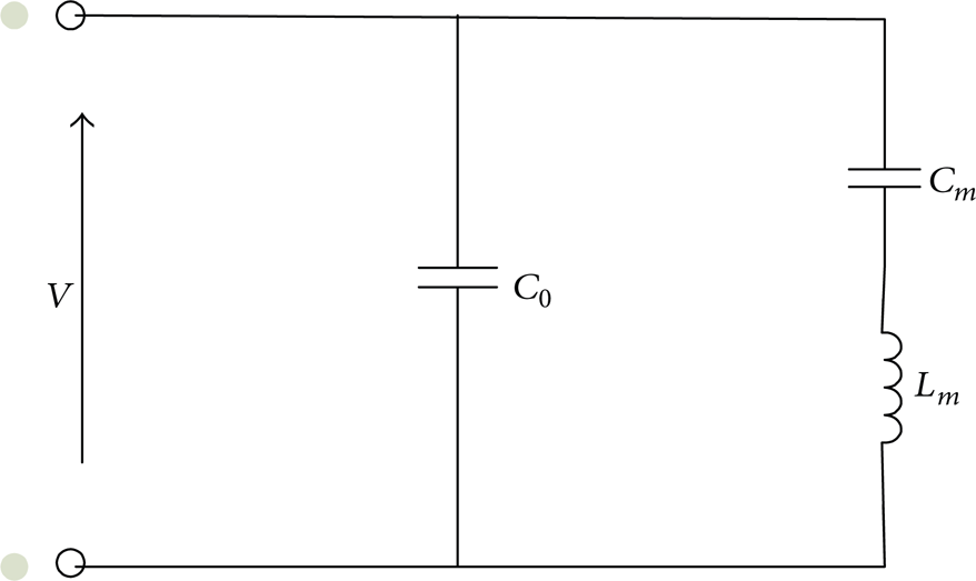
General expression of electromechanical equivalent circuit.
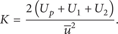
Figure 4 is a general expression of electromechanical equivalent circuit for piezoelectric transducer. The definition of effective electromechanical coupling coefficient k e can be expressed as the following description: as an unloaded piezoelectric vibrator is working at mechanical resonance vibration without considering the mechanical losses and the dielectric loss, the square root of the ratio between stored mechanical energy and total energy is called the effective electromechanical coupling coefficient. Thus, according to the definition, effective electromechanical coupling coefficient k e can be expressed as

4. Example of Sandwich Type Transducer
In this part, an example of sandwich type piezoelectric transducer is analyzed to validate the analytical model. The analyzed sandwich type piezoelectric transducer works at second order bending vibration mode. The material used for fore beam is aluminum and steel for the back beam. Material parameters are shown in Table 4. Besides, the effective electromechanical coupling coefficient of the transducer is optimized with simplex reflection technique.
Material parameters.
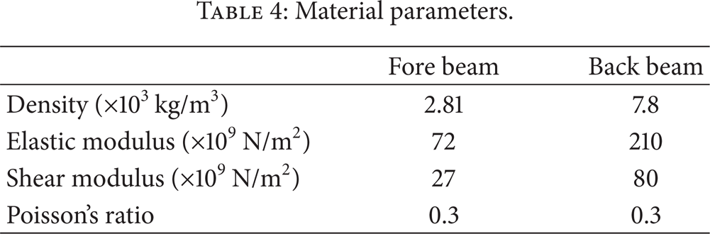
Table 5 shows the original structure parameters of the sandwich type transducer example. Substituting the parameters into the analytical model, we obtain that the resonance frequency of second order bending vibration mode is 25.665 kHz and the corresponding effective electromechanical coupling coefficient of the transducer is 30.59%.
Original structure parameters of the sandwich type transducer.

In order to obtain the optimized ratio of axial structure parameters of the transducer, the effective electromechanical coupling coefficient is optimized with simplex reflection technique. Figure 5 shows the working process of simplex reflection technique. Firstly, choose n + 1 points in the n-dimensional space as the vertex points of the original simplex. Secondly, find out the search direction and step size by calculating the evaluation of functions in each vertex point. Finally, replace the worst vertex point with the better point which is found in search direction to form a new simplex, which makes the new simplex move forward to the optimized point gradually.

Working process of simplex reflection technique.
During the optimization, the axial structure parameters L1, L2, and t are chosen as the design variables marked with x = (L1, L2, t). Electromechanical coupling coefficient is chosen as the object function. The elements of the design variable x represent the axial parameters of the transducer, and they should comply with the constraint conditions L1 > 0, L2 > 0, and t > 0.
The condition of convergence is
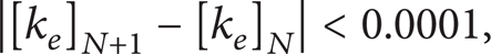
where [k e ] N and [k e ]N + 1 represent the effective electromechanical coupling coefficient of two adjacent iterations.
The initial iteration points are

The optimized point is obtained after 32 times iterations, with x* = (1.086 m, 0.244 m, 0.117 m). Then the optimized ratio of axial structure parameters of the second order bending vibration mode transducer is obtained by a normalization process:

Then we can obtain the optimized axial structure parameter, multiplying the overall length of the transducer example (96 mm) by the optimized ratio, with L1 = 58.031 mm, L2 = 13.036 mm, and t = 6.233 mm. The resonance frequency of the optimized transducer is 22.386 kHz, and the effective electromechanical coupling coefficient of the optimized transducer is 34.58%.
5. Experiment and Result
To validate the analytical model, prototype sandwich type piezoelectric ultrasonic transducers in original structure parameters and optimized structure parameters are both fabricated, as Figure 6 shows.

Prototype sandwich type piezoelectric ultrasonic transducers.
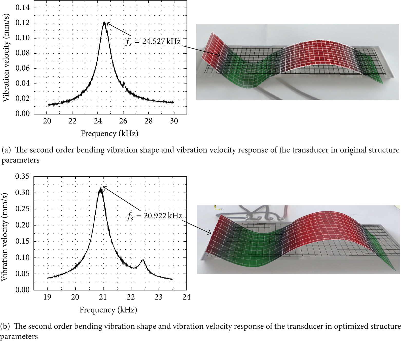
Firstly, a scanning laser Doppler vibrometer (PSV-400-M2, Polytec, Germany) is employed to measure the bending vibration modes of the prototype transducers as shown in Figure 7(a). The bottom surfaces of the transducers are taken as the testing surfaces to gain the vibration mode shapes. During the testing of the mode shape, an exciting voltage of 1.5 V is applied on the electrodes of the transducers to stimulate the bending vibration. Both ends of the prototype transducers are free-ended. Figures 8(a) and 8(b) show the vibration mode shapes of the transducers in second order bending vibration mode.

The experimental equipment.
The testing results of scanning laser Doppler vibrometer.
The graphics in Figures 8(a) and 8(b) state that the piezoelectric transducers are working at second order bending vibration mode and that the resonance frequencies for original structure sized and optimized structure sized piezoelectric transducers in second bending vibration mode are 24.527 kHz and 20.922 kHz, respectively. And there are distortions in the graphics of second order bending vibration mode. These distortions are mainly caused by the machining error and assembly error.
Secondly, an impedance analyzer (Agilent 4294A) is used to measure the impedance of the piezoelectric transducers as Figure 7(b) shows. During the impedance testing, the piezoelectric transducers are also free-ended. The impedance testing results of the transducers are shown in Figure 9. Figures 9(a) and 9(b) show the impedance and phase of the transducer in second order bending vibration mode.

The testing results of impedance and phase.
As shown in Figures 9(a) and 9(b), the impedance and phase for original structure sized and optimized structure sized transducers in second order bending vibration mode are tested in frequencies ranges of 21 kHz to 31 kHz and 18 kHz to 27.5 kHz, respectively. Resonance frequency and antiresonance frequency for the original structure sized transducer in second order bending vibration mode are 24.527 kHz and 25.925 kHz as shown in Figure 9(a). As for the optimized structure sized transducer in second order bending vibration mode, the resonance frequency is 21.087 kHz and the antiresonance frequency is 22.783 kHz as shown in Figure 9(b).
Finally, effective electromechanical coupling coefficient k e can be obtained with the impedance measurement results through [20]
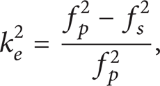
where f s is the resonance frequency and f p is the antiresonance frequency.
We may find the resonance frequencies in Figure 8 are different from those in Figure 9. For instance, in Figure 8(b), the resonance frequency for the optimized structure sized piezoelectric transducer is 20.922 kHz, while it changes to 21.087 kHz in Figure 9(b). This phenomenon is mainly caused by the different testing technique of the two different types of equipment.
Table 6 lists the results of analytical model and experimental model. As shown in Table 6, the maximum absolute error of resonance frequency between analytical model and experimental model is 1.299 kHz, and the maximum relative error is 5.80%. As for the effective electromechanical coupling coefficient, the maximum absolute error between analytical model and experimental model is −3.28%, and the maximum relative error is −9.48%. The errors are mainly caused by the simplification of the analytical model. In analytical model, the sandwich type transducer is simplified as three parts of Timoshenko beams. Another reason is the neglect of the electrodes (in the prototype, the thickness of the brass electrode is 0.2 mm). In analytical model, the electrodes thickness is not taken into consideration. The existence of electrodes in experimental prototype may influence the mechanical properties of the transducer. Besides, the machining error and measurement error are also reasons that cause the errors.
Results of the analytical model and experimental model.

6. Conclusion
In this work, an analytical model of effective electromechanical coupling coefficient for a sandwich type bending piezoelectric ultrasonic transducer is proposed. The length of each part is optimized to maximize the electromechanical coupling coefficient. In order to validate the developed analytical model, a transducer example working at second order bending vibration mode is analyzed and fabricated.
Bending vibration model of sandwich type piezoelectric transducer is first built based on Timoshenko beam theory. Elastic energy, electric energy, and electromechanical energy of the transducer are obtained based on the bending vibration model. In addition, the parameters in equivalent circuit are extracted corresponding to the energies of transducer and equivalent circuit is built. Then effective electromechanical coupling coefficient is obtained based on equivalent circuit. The optimized length of sandwich type transducer is obtained using the simplex reflection technique. After optimization, effective electromechanical coupling coefficient of the second order bending vibration transducer increases from 30.59% to 34.58%. The optimization enables the sandwich type piezoelectric ultrasonic transducer to obtain a high electromechanical coupling efficiency.
Prototype sandwich type piezoelectric ultrasonic transducers are fabricated and tested. The testing results report that effective electromechanical coupling coefficient of the prototype transducer increases from 32.34% to 37.86%. The largest absolute error between analytical model and experimental model is − 3.28%. The largest absolute error of the corresponding resonance frequency is 1.299 kHz.
Results indicate that the effective electromechanical coupling coefficient obtained from analytical model is in good agreement with that from experimental model. The analytical model provides a theoretical basis for the improvement of effective electromechanical efficiency of sandwich type piezoelectric transducers in bending vibration mode.
Conflict of Interests
The authors declare that there is no conflict of interests regarding the publication of this paper.
Footnotes
Acknowledgments
This project is supported by the National Natural Science Foundation of China (no. 51375107 and no. 51475112), the Foundation for the Author of National Excellent Doctoral Dissertation of China (no. 201428), and the Fundamental Research Funds for the Central Universities.