
Abstract
Two parallel swirling/rotating jets with a distance between them are termed biswirling jets here, which have important and complicated vortex structures different from the single swirling jet due to the negligible vortex-vortex interactions. The visualization of vortex-vortex interaction between the biswirling jets is accomplished by using direct numerical simulation. The evolution of vortex structures of the biswirling jets is found rather complicated. The turbulent kinetic energy and turbulence dissipation in the central convergence region are augmented locally and rather strongly. The modulation of turbulent kinetic energy by jet-jet interaction upon different scales of vortices is dominated by the swirling levels and the distance between the jets. The turbulent kinetic energy upon intermediate and small scale vortices in bijets with not very high swirling level and at a very close distance is smaller than that in single swirling jets, whereas the opposite is true under a far distance, and so forth.
1. Introduction
Swirling/rotating flows are frequently encountered in natural phenomenon, from small scale circumfluent indoor flows to large scale tornadoes/typhoons in the terrestrial atmosphere, and so forth. For industrial applications, the basic flow of swirling pattern, that is, the rotational motion superimposed upon the translational motion, is widely utilized in gas turbine engines, cyclone separators, swirling combustors, and so forth. In swirling flows, the “vortex breakdown” (VB) may take place when the swirl level exceeds a certain critical value, that is, an abrupt expansion of a slender vortex forming a remarkable axisymmetric “bubble” or spiral vortex [1].
The mechanism of VB and application of swirling flow in energy power engineering have been extensively investigated for many decades, either experimentally or theoretically [2–13]. For example, to improve cyclone performance of press drop and separation efficiency, Liu et al. [6] conducted a stereoscopic PIV study on the swirling flow structure in a gas cyclone by measuring the instantaneous velocities in the whole field simultaneously. Murphy et al. [8] performed numerical prediction of strongly swirling flow in an axial hydrocyclone by using two commercial CFD codes of FLUENT and CFX. Their results predicted the main feature of strong swirling flow with core recirculation and a typical Rankin vortex with inner quasi-forced vortex and outer quasi-free vortex. With regard to swirling instability, Shtork et al. [10] did an experimental LDV study of the mechanics of fluid instability in isothermal and reacting swirling flows, revealing a distinct modulation of combustion process by the hydrodynamic instability. Ranga Dinesh et al. [11] explored the instabilities of swirling flames by a large-eddy simulation-based data analysis. The generated power spectra demonstrate the oscillations of the center jet and recirculation zone. Similarly, a previous study showed the coherent oscillation of swirling flows which occur in the region of VB of strongly swirling flow [12].
Moreover, more recently, direct numerical simulations were used by a few research groups for swirling flow study [14–16]. For example, Hu et al. [14] investigated temporally evolving swirling jets with axisymmetric and nonaxisymmetric disturbance. They found the early stage of jet evolution can be well predicted by the linear stability theory, and so forth. Ruith et al. [15] performed a DNS study of swirling flow at low Reynolds numbers with jet- and wake-like axial velocity distributions, addressing the issues of the existence, mode selection, and internal structure of VB in terms of the two governing parameters, and so forth.
However, the understanding of single jet flow or heat transfer characteristics is not enough especially in energy power devices, since it always cannot provide sufficient power or produce enough global heat transfer in combustor systems when a large surface area is required to be heated or cooled. Thus, bi- and multijets [17] or jet arrays [18] are usually used in many engineering applications, such as the cooling of combustor wall, the gas turbine blades [19], the ASTOVL aircraft, the swirling burners in pulverized coal boilers of power plant, and other jet steering systems [20].
Within jet arrays, especially swirling jet arrays, the interaction between adjacent swirling jets is significant, since it will not only change the basic flow structures of the single jet, such as the feature of VB, but also modulate the turbulence characteristics. As a result, the fundamental characteristics of swirling jet array are needed to be investigated in detail. For simplicity, the flow feature of bijets is of primary importance. For this purpose, the present study is carried out to do further investigation of biswirling jets, focusing on the visualization of basic flow feature, vortex structures and interactions, and so forth.
2. Numerical Description
2.1. Governing Equations
In this study, the governing equations are in dimensionless form of the three-dimensional time-dependent Navier-Stokes equations for incompressible fluids without body force in the entire flow domain; that is,
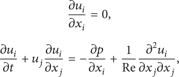
where u i , p are the velocity, pressure, respectively. Re = U0·d/ν is the Reynolds number, where U0 is the inflow velocity. d is the jet diameter at inlet, and ν is the kinematic viscosity.
To solve the governing equations, the finite difference method is applied. Upwind compact schemes [21] are used to discretize the convection term. The fourth-order compact difference schemes [22] are applied for space derivatives and pressure-gradient terms. The third-order explicit schemes are used to deal with the boundary points, to maintain the global fourth-order spatial accuracy. The fourth-order Runge-Kutta schemes [23] are used for time integration. The pressure-Poisson equation is solved to obtain the pressure.
2.2. Boundary Conditions
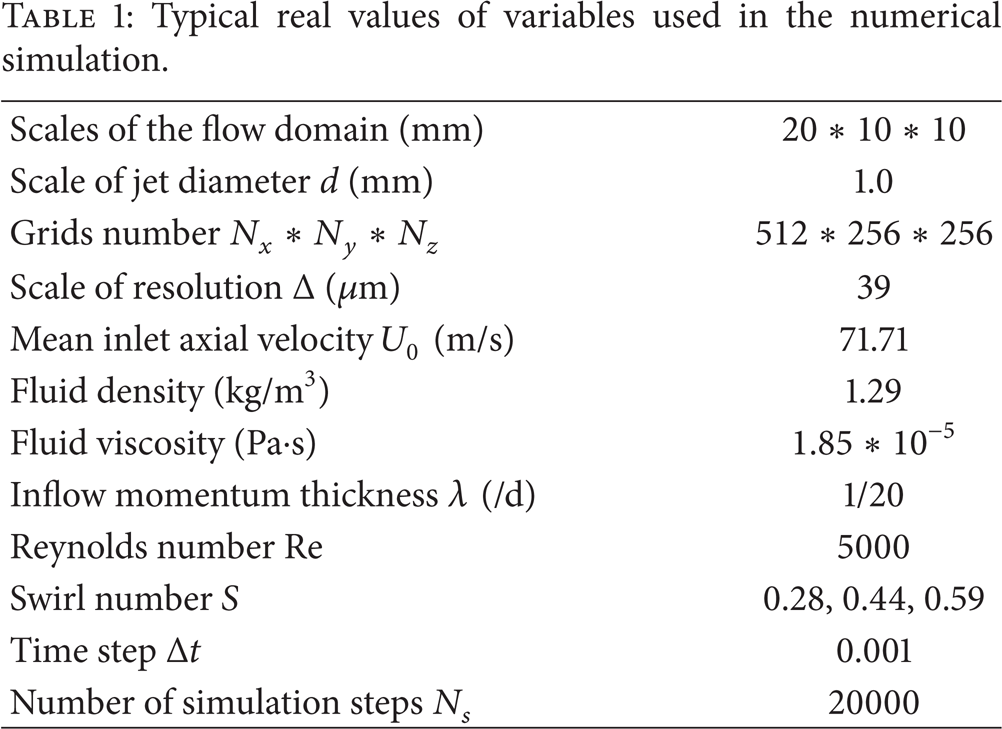
The configuration of flow is sketched in Figure 1. For simplicity, the jets are injected from an inlet with a mean velocity U0 into a rectangular flow domain of 20d × 10d × 10d, where d is diameter of the jet inlet. The entire flow domain is discretized by 512 × 256 × 256 Cartesian mesh grids. The time step is δτ = 0.001, and 20000 time steps are simulated for each case. The nonreflecting boundary condition is utilized for the outlet condition [24], and the side walls are set nonslipping wall boundaries.
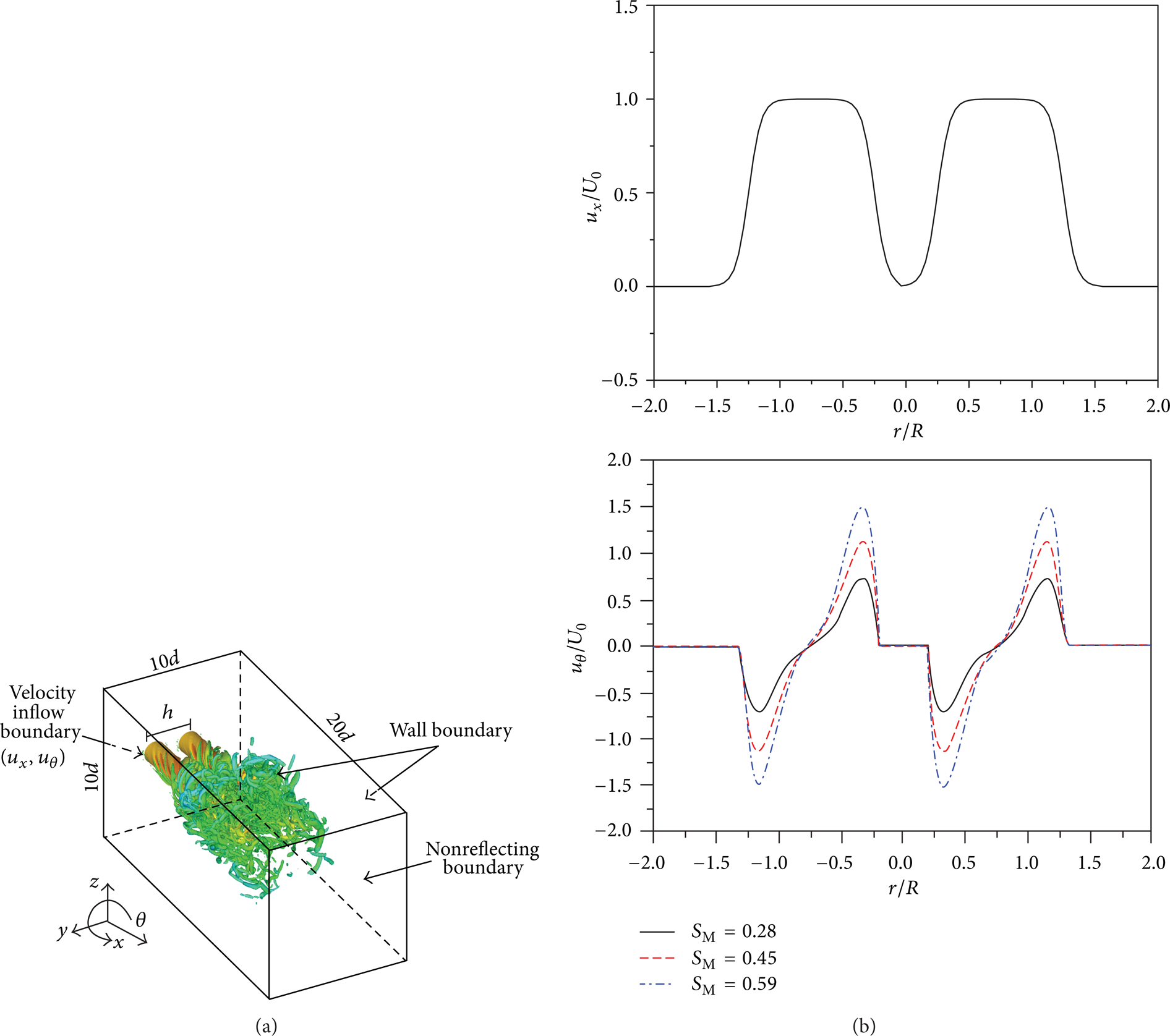
Sketch of the simulation setup and twin coswirling jets (SM = 0.28, h = 1.5d), and the inflow velocity profiles (u x , axial velocity; uθ, azimuthal velocity).
With regard to the accuracy for space discretization, it is well accepted that the smallest Kolmogorov length scale ηkol is needed to be captured in direct numerical simulation, at least in the same order with the finest mesh spacing Δ m . In one of our previous works on direct numerical simulation of swirling flow [25], it used 384 × 128 × 128 = 6291456 meshes for Re = 3000 to guarantee ηkol∼Δ m . In this study it used 512 × 256 × 256 = 33554432 meshes for Re = 5000. As the number of meshes for direct numerical simulation follows N m ∼Re3 for both spatial and temporal accuracy, it is (33554432/6291456) = 5.33 > (5000/3000)3 = 4.63. Thus, the mesh spacing in this study meets the accuracy requirement of direct numerical simulation. Moreover, with 256 mesh grids in the lateral direction, the jet inlet is discretized by 25 mesh grids. It is fine enough for present simulation.
The combined hyperbolic tangent profile is used for axial inflow velocity. Within the range of |r − r c | < d/2, it follows the form of
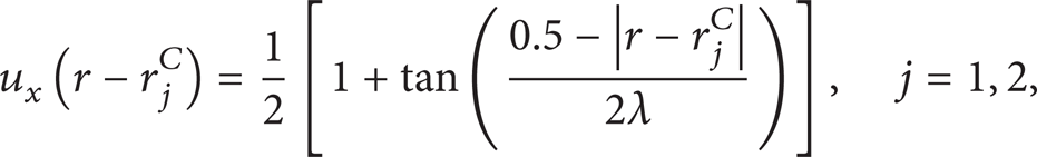
where r j C is the center position of the jth jet. λ is the inflow momentum thickness (Table 1), and the ratio of the jet width to the inflow momentum thickness is d/λ = 20. Moreover, to model the azimuthal inflow velocity, a combined polynomial expression is used. In general, it has the form of

Typical real values of variables used in the numerical simulation.
In this study, only the first six terms are used with the highest order of n = 5, and the coefficients a i are listed in Table 2. The combined profiles of axial and azimuthal velocities are shown in Figure 1. In addition, no initial turbulence is introduced to show the intrinsic full evolution of coherent vortex structures and interactions.
Coefficients of the expressions for inflow velocity uθ.

In most engineering viewpoints, the swirl number SM is defined as the ratio of the axial flux of angular momentum to the axial momentum, that is,

Based on (2) and (3), three swirl numbers are used (Table 2). For SM = 0.28, it is considered as a low swirl jet, whereas SM = 0.59 is considered as a strongly swirling flow. For comparison, two values of distances h (Figure 1) between the centers of the bijets are used, that is, h = 1.5d and h = 3d for each swirl number. Moreover, the cases with single swirling jets are simulated for comparison.
3. Results and Discussions
3.1. Vortex Visualization
3.1.1. Vortex under Different h
For comparison, the typical vortex structures under different h are shown in Figures 2(a)–2(c). They are visualized by the λ2 criteria. The λ2 criteria were proposed by Jeong and Hussain [26]. In general, the velocity gradient tensor ∇

Isosurface of vortex cores (λ2 = − 50, flood by axial velocity u x ) of the twin coswirling jets for SM = 0.59 at t = 45 ((a) single jet; (b) twin jets with h = 1.5d; (c) twin jets with h = 3.0d) and for SM = 0.28 (d), 0.45 (e), and 0.59 (f) with h = 3.0d and t = 20.
In single swirling jet, only a few strong swirling vortex cores are formed (Figure 2(a)), which appear around the peripheral annular region of the jet sparsely. However, for biswirling jets (Figures 2(b) and 2(c)), lots of strong swirling vortex cores are established, especially in the central region between the biswirling jets, where the interaction between the bijets is very intensive. It is seen that the distribution of generated vortex between the jets is much denser than in other regions. Moreover, with a short distance between the bijets (h = 1.5d in Figure 2(b)) not only the central region but also the annular peripheral region is distributed with denser strong vortex cores. With a bit longer distance between the bijets (h = 3.0d in Figure 2(c)), the density of generated strong vortex and the area covered by strong vortex are a bit lower than the former. Thus, the results show clearly the occurrence of the strong interaction of swirling vortex cores between the bijets. The closer the bijets are, the stronger the vortex interaction will be.
3.1.2. Coherent Vortex Structures with Different SM
Figures 2(d)–2(f) show the typical coherent vortex structures of different swirling numbers SM with h = 3.0d. When SM is low (SM = 0.28, Figure 2(d)), the annular vortex cores from each of the swirling jets are weakly coupled. In the joint region, the vortex rings are deformed and interrupted, and new small scale rings are rebuilt for pairing. Under an intermediate swirling level (SM = 0.45, Figure 2(e)), the annular strong vortex cores are twisted, forming fairly intensive swirling vortex cores. More importantly, the topological structure of coherent vortex is changed when the direct contact and interaction of vortex cores occur in the central region. In addition, under a large swirling level (SM = 0.59, Figure 2(f)), the ring structure of annular vortex cores and the structure of twisted swirling cores around the ring become even more complex. Large scale deformation and strong interaction between vortex cores occur more evidently. Thus, the results show the great effect of swirling level on the coherent vortex structures and interactions in the biswirling jets.
3.2. Turbulent Kinetic Energy
Based on the features of vortex cores, it validates the existence and shows the great effects of vortex-vortex interaction in twins swirling jets. Thus, it is necessary to investigate the effect of vortex interaction on turbulence modification. Firstly, the turbulent kinetic energy (TKE) in the biswirling jets is defined as follows:

where u i ′ is root-mean-square value of velocity in the ith direction. For simplicity, we use k′ = (u i ′2)1/2 instead here.
For example, Figure 3(a) shows the TKE of the bijets at different distances in the central plane z = 0 at x = 1.875d. For the case of single jet (s.j.), it is seen that TKE is large near the center of the jet (y/d = 1.5) and in the peripheral annular region (about y/d = − 1 and y/d = 4), that is, the region with strong vortex cores (Figure 2(a)). The profiles of TKE in the annular region of the bijets (about (y − y c )/d = 2.5, y c is the central location of the jet) are almost in the same order of the single jet. In contrast, the TKE in the center of the bijets around y/d = 0 are greatly augmented in the bijets compared to the single jet, even much larger than in the center of any single jet. It validates the strong effect of vortex-vortex interaction on augmentation of turbulence.

Turbulence fluctuation velocity in the central plane of z = 0 at x = 1.875d ((a) for SM = 0.59 with different h; (b) for h = 3.0d with different SM) (s.j. means single jet; t.j. means twin jet, and the same hereafter) and (c) the three-order turbulence fluctuation at the same place.
On the other side, Figure 3(b) shows the TKE in different swirling level jets. For SM = 0.28, only two peaks exist, corresponding to occurrence of the ring-type swirling vortex (Figure 2(d)). The central peak disappears due to formation of the central recirculation zone (CRZ) and the vortex breakdown (VB) does not take place under low level swirling jets. Moreover, the two annular peaks of the bijets are separated, and the TKE in the center of the bijets (y/d = 0) are almost zero. For SM = 0.45, large TKE occurs in the central region of each jet (y/d = ± 1.5), corresponding to occurrence of the recirculated flow and bubble-type VB. Moreover, the two annular peaks in the center of the twin jet are contacted, corresponding to the weak correlation of vortices as well as the change of topological structures of coherent vortex in Figure 2(e). On the contrary, for large swirling level SM = 0.59, not only the TKE in the central (y/d = ± 1.5) and annular (y/d = ± 4) region of each jet are increased slightly, but also the TKE in the center of the bijets (y/d = 0) are greatly augmented, corresponding to the very strong vortex-vortex interaction and rather complicated coherent vortex structures in this region (Figure 2(f)). Thus, it clearly indicates that the strong vortex-vortex interaction between the bijets significantly modulates the turbulence through TKE augmentation in the center region, especially for the strongly swirling jets.
In addition, Figure 3(c) shows the three-order turbulence fluctuation in the same place. As the three-order fluctuation (TOF) can have negative values, it is found that the TOFs in the center of each jet (y/d = ± 1.5) are negative, indicating the clear occurrence of CRZ and VB. However, the TOFs in the center of the twin jet (y/d = 0) are positive, showing the augmentation of high-order turbulence by strong vortex-vortex interaction in this region. These results confirm the conclusions obtained from Figure 3(b).
3.3. Turbulent Dissipation Rate
On the other side, the turbulent dissipation rate (TDR) is important for study of turbulence. Thus, it is necessary to investigate the characteristics of turbulent kinetic energy dissipation in bijets. In general, the TDR can be written as

where ν is the kinematic viscosity. In this section, we used an equivalent term ε = 〈∂ k u i ′ ∂ k u i ′〉 instead for simplicity.
The contours of TDR ε for SM = 0.28 and SM = 0.59 on a cross-sectional plane (x = 1.875d) are shown in Figures 4(a) and 4(b), respectively. Referring to the coherent structure of vortices in Figure 2, the TDR distribution within this region is closely dependent on the coherent vortex structures. In Figure 4(a) (SM = 0.28, h = 3d), the distribution of TDR for each jet is composed of axisymmetric six tilted wavy coherent structures. It is localized and restricted around the core region with strong vortex cores. Thus, in low swirling level flows, the TDR in the region between the jets is negligible. However, in Figure 4(b) (SM = 0.59, h = 3d), the TDR are greatly different from the former. Firstly, the radius of the annular distribution becomes larger. The regular tilted wavy structure is significantly disturbed, spreading around the annular rings. Secondly and more importantly, two rings are kept in contact, and evident strips of large TDR appear in the contact region. It seems that the TDR is of great significance within the intermediate and interaction region between the jets.

TKE dissipation ε = 〈∂ k u i ′ ∂ k u i ′〉 within the plane of x = 1.875d of the twin jets ((a) h = 3.0d, SM = 0.28; (b) h = 3.0d, SM = 0.59) and its probability distribution function P(ε) within the major central recirculation zone from x = 1.25d to x = 2.5d ((c) P(ε) for h = 3.0d; (d) P(ε) for h = 1.5d).
To quantify the distribution of TDR, we calculate the probability distribution function P(ε) here. The P(ε < δ) means the portion of volume with ε < δ or equivalently the occurrence probability of ε < δ within the major CRZ. The major CRZ is corresponding to the core region of vortex breakdown, which is designated from x = 1.25d to x = 2.5d here. To facilitate the comparison, the ε is normalized by the root-mean-square value of it. From Figures 4(c) and 4(d), it is found that (1) comparing to single jet when δ is the same and small, the P(ε′ < δ〈ε′〉) of bijets have smaller values, except SM = 0.59 for strongly swirling flows. It means the distribution of TDR with smaller fluctuations occurs more probably in single jet, or equivalently, the intensive variation of TDR distribution occurs more frequently in bijets than in single jet. It is reasonable, since the distribution of coherent vortex structure in bijets is much more complicated than that in single jet. (2) Compared to low swirling level jets, stronger swirling flows have smaller values of P(ε′ < δ〈ε′〉) when δ is small. To reach the same P(ε′ < δ〈ε′〉), the larger δ (namely, larger fluctuation level) is needed for strongly swirling flows. It is also reasonable, since the TDR in strongly swirling flows should be larger than that in low level swirling flows. (3) The increase rate of P(ε) indicates the local probability of TDR. For strongly swirling flows (SM = 0.59), we see that the P(ε) for bijets increases more rapidly than single jet around δ∼O(1), namely, ε′∼O(〈ε′〉), where the operator “O(+)” denotes the same order. It means the larger probability of variation of TDR around O(〈ε′〉) in twin strongly swirling jets comparing to the single strongly swirling jets. Note that, under the same way of low swirling flows, the P(ε) in strongly swirling flows follows the imaginary curve to increase (in Figure 4(c)). Thus, the significant rapid increase in P(ε) in strongly swirling flows indicates the greater effect of vortex-vortex interaction upon turbulence characteristics in strongly swirling flows than that in weakly or intermediate swirling flows.
3.4. Spectrum Analysis
In this section, we do some discussions on the spectrums of TKE and TDR to implement further investigations of the modulation characteristics of turbulence in biswirling jets. The TKE energy spectrum

where û
i
(
As shown in Figure 5(a) (h = 3d), it is found that (1) for low and intermediate swirl level flows (SM = 0.28 and 0.45), the TKE energy spectrum of bijets in the whole CRZ region is larger than that of single jet, especially in the range of 0.1 < ξη < 1 (namely, η < lvor < 10η, where lvor is the vortex characteristic length scale). It means that for low swirl flows the TKE energy of small vortices (within the range of η < lvor < 10η) in bijets is larger than the single jets. (2) On the contrary, for strongly swirling flows (SM = 0.59), the TKE energy spectrum of bijets is smaller than the single jet, within the range of 0.01 < ξη < 1 (namely, η < lvor < 100η). It indicates that the TKE energy of bijets is smaller than the single jet for the small and intermediate vortices. But for the large scale vortices (lvor > 100η), the TKE energies for the bijets and the single jets are equivalent to each other.

TKE spectrum
But in Figure 5(b) (h = 1.5d), it is seen that only the trends for the strongly swirling flows are similar to the former, especially for the intermediate scale vortices (0.01 < ξη < 0.2 and 5η < lvor < 100η). The trend for the low swirling level flow (SM = 0.28) is opposite to the former; that is, the TKE energy of bijets is lower than the single jet within the range of 0.01 < ξη < 1 (namely, η < lvor < 100η).
In other words, the modulation of TKE energy distribution upon various scales of vortices by the bijets depends on both the distance between the jets and the swirling levels. For close distance and high swirling level, the vortex-vortex interaction between the biswirling jets should be strong and complicated. Then the TKE energy distributed upon intermediate and small scale vortices (typically η < lvor < 100η) is smaller in the bijets than in the single jet. It is reasonable, since the strong vortex-vortex interaction and complicated coherent vortex motion should dissipate the global TKE rapidly and greatly for strongly swirling flows in close distance. On the other side, for large distance and weak swirling flows, the vortex-vortex interaction between the bijets should be relatively less intensive than the former or only weakly correlated. In this condition, the TKE energy distributed upon the intermediate and small scale vortices in bijets is larger than that in single jet. It is also reasonable, since the bijets have much more TKE input than the single jets.
Moreover, under the same swirling level (below strongly swirling level with VB), the discrepancy of TKE energy of intermediate and small scale vortices between the bijets and single jet becomes decreased when the distance between the jets h decreases (e.g., see insets of Figures 5(a) and 5(b), from h = 3.0d to h = 1.5d for SM = 0.45), or even the opposite discrepancy occurs (e.g., see insets of Figures 5(a) and 5(b), from h = 3.0d to h = 1.5d for SM = 0.28). It is due to the increased intensity of vortex-vortex interaction and consequently increased dissipation of TKE when the bijets kept closer.
On the other side, under the same strongly swirling level (SM = 0.59), due to the formation of VB and CRZ, the TKE energy distribution is not only related to vortex-vortex interaction, but also related to the combination of VB and CRZ. In this way, it is found that the TKE energy distributed on small scale vortices in bijets is almost the same as that in single jet when the bijets are kept very close (0.7 < ξη < 1 in Figure 5(b)). Then, when they leave each other at much larger distance, the trends become the same as the large scale vortices (Figure 5(a)). It indicates that (1) under the high dissipation rate of TKE in strongly swirling flows, the TKE in bijets are lower than in single jet upon almost all scales of vortices; (2) however, with the bijets kept close enough, the interaction of large scale coherent structure, that is, the combination of CRZ or VB region, plays an important role in maintaining energy dissipation of TKE in smallest scales turbulence (the order of dissipation scale of turbulence). It may be possibly because, under this special condition of CRZ combination, the TKE dissipation dominated by the complicated large scale coherent vortex motion is so large that it has no enough time for TKE to be transported to the finest dissipation scale before it is totally dissipated.
4. Conclusion
The present study did a direct numerical simulation of twins swirling jets, showing the coherent structure and vortex-vortex interaction and the turbulence characteristics modulated by the vortex-vortex interaction in bijets.
The coherent vortex structure in the center of the bijets is rather complicated, accompanied with rather strongly and locally augmented turbulent kinetic energy and turbulence dissipation, as well as high-order correlated turbulent fluctuations in that region under strongly biswirling jets in a close distance. The TDR is then rapidly increased in probability distribution function upon the order of root-mean-square values of it.
Based on the observations and analyses of the energy spectrum, it is clear that the modulation of TKE distribution upon different scales of vortices is dominated by the swirling levels and the distance between the jets. In general, for not very high biswirling jets with a very close distance, the TKE distribution upon intermediate and small scale vortices in bijets is smaller than that in single jets, whereas the opposite becomes true under a far distance. It indicates the significant role of vortex-vortex interaction in TKE dissipation for much closer bijets. For the strongly biswirling jets, the TKE distribution for the bijets and single jet upon very small scales of vortices (the order of turbulence dissipation scale, lvor∼O(η)) is almost the same when the jets are kept close, whereas at a far distance, the TKE distribution of bijets upon intermediate and small scales of vortices is smaller than the single jet. It indicates the significant effect of VB/CS-dominated TKE dissipation; that is, the CS-dominated TKE dissipation is so large that most of the TKE cannot be transported to the finest dissipation scale before it is dissipated.
Conflict of Interests
The authors declare that there is no conflict of interests regarding the publication of this paper.
Footnotes
Acknowledgments
The authors are grateful for the support of this work by the National Natural Science Foundation of China (51106180) and the China Postdoctoral Science Foundation (2013M540964).