
Abstract
Research on the efficiency improvement of pump as turbine (PAT) is inadequate. Blade thickness is an important geometry parameter in blade design. To explore effects of blade thickness on the influence of PAT, numerical research on three different specific speeds of PATs with different blade thickness was carried out. Their performance changes with blade thickness were presented. Besides, the variations of hydraulic loss distribution with increasing blade thickness were performed. Theoretical analysis gives a reasonable explanation for the performance change. Results show thatPAT's flow versus efficiency curve (Q-η) is lowered; flow versus head (Q-H) curve and flow versus power (Q-P) curve are increased with increasing blade thickness. The increase of Q-P is mainly attributed to the increase of theoretical head caused by increasing blockage of impeller inlet area. Hydraulic loss distribution analysis indicates that the total hydraulic loss within PAT is increased with increasing blade thickness. The increase of Q-H curve is a combined effect of the increase in theoretical head and the total hydraulic loss. The decrease of efficiency with increasing blade thickness indicates that the blade thickness of PAT should be as thin as possible if its strength could be met.
1. Introduction
Pumps are reversible machines. A pump can run as a turbine with an acceptable efficiency. Due to its apparent advantages of being cheap and readily available worldwide, pump as turbine is one of the best options for small hydropower recovery [1–4].
The efficiency of PAT is reported to be almost the same as in pump mode [5]. The efficiency improvement of PAT means generating more energy from current limited hydropower resources. Therefore, researchers have been focused on its efficiency improvement. Singh and Nestmann [6, 7] carried various possibilities of modifying current pump geometry to improve its efficiency. Yang et al. analyzed the flow field [8] within PAT and investigated effects of splitter blades [9] and blade wrap angle [10] on the performance influence of PAT. Yang et al. [11] sought to find out a high efficiency PAT's volute design method through numerical research into volute main geometric parameters influencing PAT. Derakhshan et al. [12, 13] used a gradient-based optimization algorithm to optimize PAT's blade profiles. As could be seen research on the efficiency improvement of PAT is inadequate. Blade thickness is a main geometry parameter to be determined in hydraulic design. Therefore, this paper seeks to find the effects of blade thickness on the influence of PAT.
Experimental and numerical researches are two ways frequently adopted in PAT's research. Experimental research could give people a convincing result. However, it has the drawbacks of being time consuming and expensive. Besides, limited by the accuracy of test bed, small changes of performance may not be easily observed. CFD as a promising technique provides a powerful substitution and has been used in the research of rotating machinery [14, 15] and PAT [16, 17]. In this paper, effects of blade thickness influencing different specific speeds of PATs’ performances were investigated using a validated CFD approach. Hydraulic loss distribution and theoretical analysis were performed; the reasons for the variation of PAT's performance were explored.
2. Numerical Investigation
2.1. Main Geometric Parameters
PATs covering low, medium, and high specific speeds were designed. Table 1 lists their design parameters. Table 2 lists their main geometric parameters [18].
Design parameters of the PATs.

Main geometric parameters of the PATs.

2.2. Mesh Generation
ICEM-CFD was used to generate structured hexahedral grid for each component part [19]. A grid independent test of the low specific speed PAT was performed; it was found that when mesh elements were around 1 million, the variation of efficiency was within 0.5%. The final mesh number of the PAT was over 1 million. The y+ near the boundary wall was around 40 [20]. For comparison, mesh number of different designs was almost the same. Figure 1 gives a general view of the generated meshes.

Mesh of PATs.
2.3. Solution Parameters
ANSYS-CFX was selected in the solution of 3D Navier-stokes due to its characteristics of being robust and having fast convergence. Steady state simulation was carried out. The turbulence selected was standard k-ε model. The advection scheme was set to high resolution. The convergence criterion was 10−6. The fluid selected was ideal water at 25°C. All the wall surface roughness within the control volume was set to 50 μm. Standard wall function was used for the boundary layer treatment. The boundary conditions were set to inlet, static pressure, and outlet, mass flow outlet [21, 22]. By changing the mass flow rate, performance curves of the PAT were acquired. The interfaces between two stationary components and rotary and stationary components were set to general grid and rotor stator interface, respectively.
3. Validation of Numerical Simulation
3.1. Experimental Set-Up
A laboratory model of an open PAT test rig, as shown in Figure 2, was set up at Jiangsu University. High pressure fluid required for PAT's energy recovery was supplied by a feed pump. An electric eddy current dynamometer (EECD) was installed to measure and consume energy generated by PAT and to regulate its rotational speed. The discharge was measured by a turbine flow meter. PAT's inlet and outlet pressures were measured by pressure sensors. The uncertainties of measured required pressure head H, flow rate Q, hydraulic power P h , generated shaft power P, and efficiency η are ± 0.14%, ± 0.50%, ± 0.52%, ± 1.08%, and ± 1.20%, respectively.

An open PAT test rig.
3.2. Comparison between Numerical and Experimental Results
PAT with specific speed of 57 was selected for the validation of numerical accuracy. The blade thickness of test PAT is 4 mm. Other geometric parameters are listed in Table 2. Figure 3 shows the test PAT. Comparison between experimental and numerical results is presented in Figure 4.

Test PAT.

Comparison between experimental and numerical results.
As is shown in Figure 4, the tendency of PAT's numerical predicted performance curves is in agreement with those of experimental. Numerical predicted efficiency, pressure head, and shaft power are higher than those of experimental. The overprediction of efficiency, pressure head, and shaft power may attribute to the neglect of leakage loss through balancing holes, surface roughness value set, and mechanical loss caused by mechanical seal and bearings. The comparison between experimental and steady state numerical results indicates that the grid and turbulence model selected are reasonable for PAT's performance prediction. As a result, ANSYS-CFX can be used to predict the performance of PAT.
4. Results and Analysis
4.1. Performance Analysis
Numerical simulations of three PATs with different blade thickness were performed. The main geometric parameters of the investigated PATs are listed in Table 2. Figure 5 plots their performance curves. Table 3 lists their performance at their BEPs.
PAT's BEPs of impellers with different blade thickness.

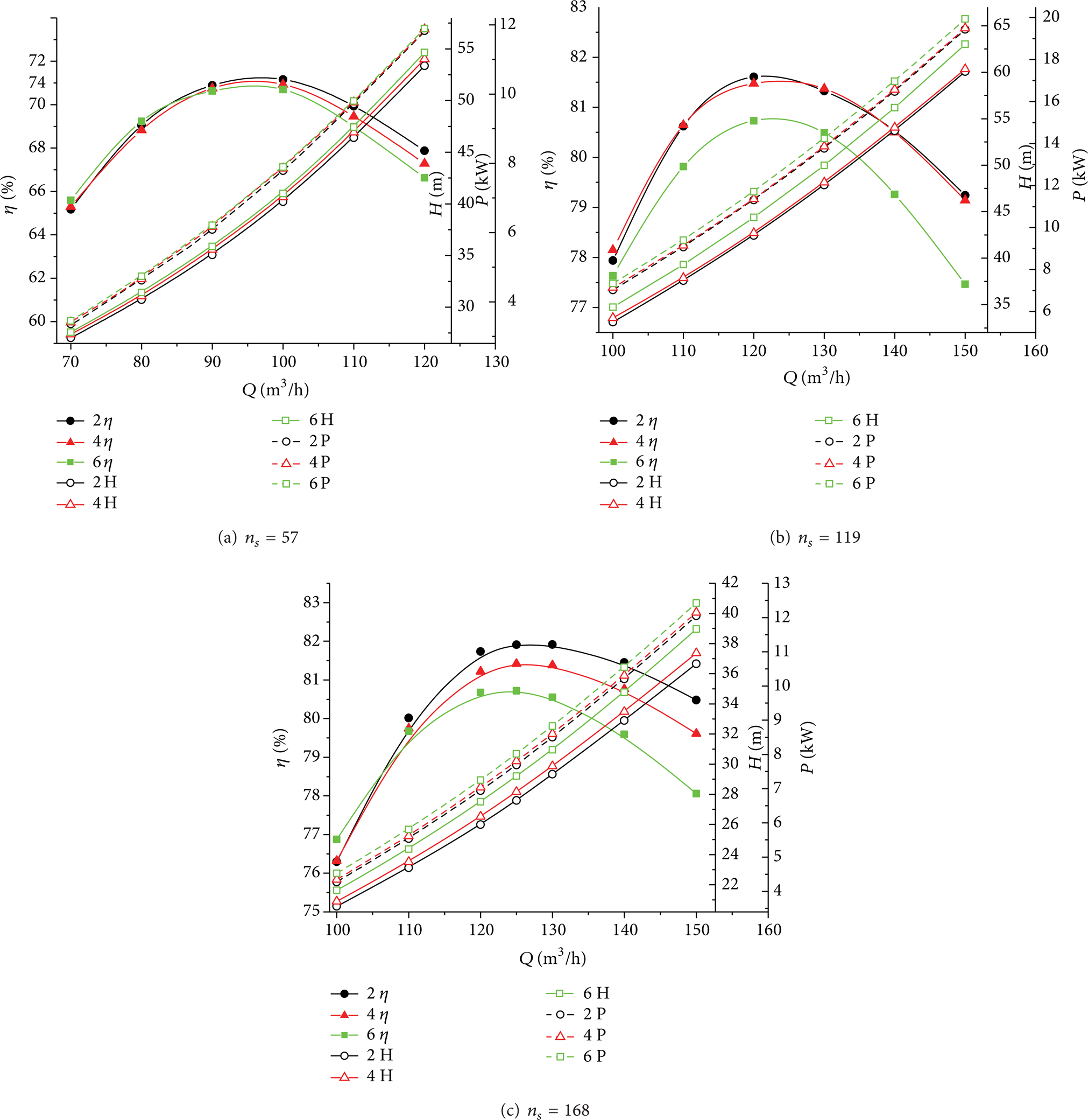
Performance curves of PATs with different blade thickness.
Figure 5 and Table 3 show that PAT's Q-H and Q-P curves are increased; Q-η curve is lowered with the increase of blade thickness. This illustrates that for the same flow rate its required pressure head and generated shaft power are increased and its efficiency is decreased when there is an increase of blade thickness. Thus, it can be concluded that for the efficiency improvement blade thickness should be as thin as possible, supposing that its strength is satisfied.
4.2. Hydraulic Loss Distribution Analysis
The variations of hydraulic loss distribution with blade thickness within PATs’ three zones (volute zone to outlet pipe zone as defined in Figure 6) are discussed in this section. The difference of hydraulic loss distribution between impellers with blade thickness of 2 mm and other blade thicknesses is presented in Figure 7. Table 4 lists their hydraulic loss difference at their BEPs.
Lists of hydraulic loss differences at their BEPs.


Flow zones in a PAT control volume.

Difference of hydraulic loss distribution with different blade thickness.
As indicated in Figure 7 and Table 4, the hydraulic loss within impeller and the total hydraulic loss are increased with increasing blade thickness. The hydraulic loss within volute of the low specific speed PAT is grown, while that within the volutes of the medium and high specific speed PATs is dropped. And the variation of hydraulic loss within outlet pipe is negligible. It can be concluded that the growth of hydraulic loss within impeller is mainly responsible for the increase of total hydraulic loss within PAT with increasing blade thickness. The hydraulic loss within impeller can be calculated by equation himpeller = kQ2. Table 4 shows that, as blade thickness increases from 2 mm to 6 mm, the hydraulic loss factor k is increased by 1.89%, 19.22%, and 30.50% for the low, medium, and high specific speeds of the PATs at the BEP.
4.3. Flow Field Analysis
The velocity streamline distribution at the middle span of impeller blade to blade surface is presented in Figure 8. For the purpose of comparison, the flow rate is the same for both cases. It can be seen from Figure 8 that the velocity within impeller is increased with increasing blade thickness. The local and frictional hydraulic is in proportion to the square of velocity; therefore its hydraulic loss within impeller is increased with increasing blade thickness.

Streamline distribution within PAT.
5. Theoretical Analysis
5.1. Output Shaft Power
From the fundamentals of energy transfer in turbines (steady flow equation and Euler turbine equation), the output mechanical shaft power can be represented by (1) [23–25]:


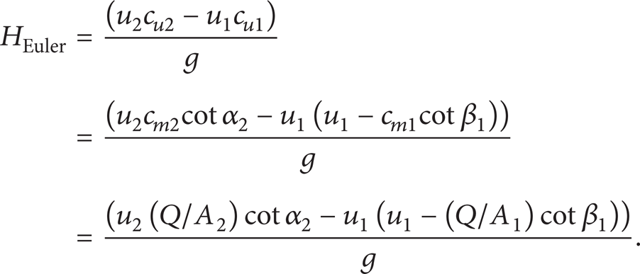
As could be seen from (1), (2), and (3), PAT's Q-P curve is in inverse proportion to inlet area A2. Figure 9 shows two blades with different thickness. An increase of blade thickness would cause a decrease of impeller inlet area ΔA2. Therefore, there would be an increase of the theoretical head ΔH t and the generated shaft power ΔP. Thus, we could see that PAT's Q-P curve would increase with the increase of blade thickness, which is in agreement with the results presented in Section 4.1.

Variation of blade thickness.
5.2. Required Pressure Head
PAT's required pressure head can be represented as the sum of theoretical head and the losses within all the three zones of the PAT's control volume illustrated in

Hydraulic loss distribution (Section 4.2) and theoretical head (Section 5.1) analysis shows that the total hydraulic loss htotal and theoretical head H t are increased with the increase of blade thickness. Therefore, PAT's Q-H curve will also increase which is in agreement with the results in Figure 5.
5.3. Efficiency
PAT's hydraulic efficiency can be represented by

An increase of blade thickness would cause an increase of both theoretical head and total hydraulic loss. Therefore, PAT's efficiency is decreased when there is an increase of blade thickness.
6. Conclusions
Research on blade thickness to the influence of PAT was performed numerically. PAT's performance of different blade thickness was presented. Results show that its Q-η curve is lowered and Q-H and Q-P curves are increased with increasing blade thickness. It could be concluded that from the efficiency point of view the blade thickness is expected to be as thin as possible.
Hydraulic loss analysis within PAT indicates that, with the increase of blade thickness, the hydraulic loss within impeller and the total hydraulic loss are increased. The hydraulic loss within volute of the low specific speed PAT is grown, while that within the volutes of the medium and high specific speed PATs is dropped. The variation of hydraulic loss within outlet pipe is negligible. Flow field analysis indicates that it is the increase of velocity within impeller that caused the increase of hydraulic loss within impeller. Theoretical analysis shows that the theoretical head is increased with the increase of blade thickness. Therefore, PAT's output power is increased. PAT's actual required pressure head is the sum of theoretical head and the total hydraulic loss within PAT's control volume. Thus, the head curve is increased as blade thickness is increased.
Footnotes
Nomenclature
Conflict of Interests
The authors declare that there is no conflict of interests regarding the publication of this paper.
Acknowledgments
This paper is financially supported by the Natural Science Foundation of Jiangsu Province entitled “Research on impeller internal flow and design theory of pump as turbine (BK20130517)” and Jiangsu University Foundation (13JDG081), A Project Funded by the Priority Academic Program Development of Jiangsu Higher Education Institutions (PAPD).